EP0891792B1 - An ice skate with interchangeable blades - Google Patents
An ice skate with interchangeable blades Download PDFInfo
- Publication number
- EP0891792B1 EP0891792B1 EP98202235A EP98202235A EP0891792B1 EP 0891792 B1 EP0891792 B1 EP 0891792B1 EP 98202235 A EP98202235 A EP 98202235A EP 98202235 A EP98202235 A EP 98202235A EP 0891792 B1 EP0891792 B1 EP 0891792B1
- Authority
- EP
- European Patent Office
- Prior art keywords
- blade
- holder
- skate
- tie
- skate according
- Prior art date
- Legal status (The legal status is an assumption and is not a legal conclusion. Google has not performed a legal analysis and makes no representation as to the accuracy of the status listed.)
- Expired - Lifetime
Links
- 230000008878 coupling Effects 0.000 claims description 10
- 238000010168 coupling process Methods 0.000 claims description 10
- 238000005859 coupling reaction Methods 0.000 claims description 10
- 230000000452 restraining effect Effects 0.000 claims description 7
- 230000008901 benefit Effects 0.000 description 3
- 230000008859 change Effects 0.000 description 1
- 239000000463 material Substances 0.000 description 1
- 230000004048 modification Effects 0.000 description 1
- 238000012986 modification Methods 0.000 description 1
- 238000000465 moulding Methods 0.000 description 1
- 229920003023 plastic Polymers 0.000 description 1
- 239000004033 plastic Substances 0.000 description 1
- 230000009467 reduction Effects 0.000 description 1
- 230000001105 regulatory effect Effects 0.000 description 1
Images



Classifications
-
- A—HUMAN NECESSITIES
- A63—SPORTS; GAMES; AMUSEMENTS
- A63C—SKATES; SKIS; ROLLER SKATES; DESIGN OR LAYOUT OF COURTS, RINKS OR THE LIKE
- A63C1/00—Skates
- A63C1/30—Skates with special blades
- A63C1/303—Skates with special blades removably fastened to the blade holder
Definitions
- the present invention relates to an ice skate with interchangeable blades according to the preamble to the main claim.
- ice skates which have blades arranged for fixing releasably to the body of the skate so that the user can change the blade without having to replace the body of the skate or the associated boot are known.
- These skates generally only permit interchangeable replacement of blades of identical configuration and the user is consequently forced to equip himself with a different pair of skates for each of the skating disciplines which he intends to practice such as, for example, ice hockey, for which short, thick blades are required, or speed skating for which, on the other hand, relatively long, thin blades are required.
- skates in which the blade is arranged to be fixed to a blade-holder which in turn is intended to be clamped against the body of the skate.
- this type of skate also only permits interchangeable replacement of blades of identical geometrical configuration and consequently has the same disadvantages for the user as that described above.
- the problem upon which the present invention is based is that of providing an ice skate which is designed structurally and functionally so as to overcome all of the problems complained of with reference to the prior art mentioned.
- a first embodiment of an ice skate with interchangeable blades formed in accordance with the present invention is generally indicated 1.
- the skate 1 comprises a partially hollow body 2 carrying an attachment flange 3 for fixing to the body of a boot 4, shown only partially in the drawings.
- the body On the opposite side to the attachment flange 3, the body has a groove 5 constituting a seat for housing a blade-holder 6a arranged for supporting a respective blade 7a and for being clamped against the body 2, as will be described in detail below.
- the skate 1 also comprises a plurality of sets of blades and respective blade-holders which are interchangeably replaceable in the seat 5 of the body 2.
- Figures 5 to 7 show three embodiments of sets of blades and respective blade-holders, generally indicated 8a, 8b and 8c, the blades 7a, 7b, 7c of which have different geometrical configurations, designed specially for different skating disciplines.
- the blade 7a of the set 8a is particularly suitable for ice hockey since it is relatively short and noticeably thick ( Figures 5 and 11).
- the blade 7b of the set 8b has geometrical characteristics of length, thickness and curvature designed appropriately for figure skating.
- the blade 7c of the set 8c is longer and thinner than the blades of the previous sets and is particularly suitable for speed skating.
- Each set 8a, 8b, 8c comprises a respective blade-holder 6a, 6b, 6c arranged for supporting the corresponding blade 7a, 7b, 7c.
- each blade-holder is made of plastics material and is co-moulded on the blade of the corresponding set.
- each blade-holder 6a, 6b and 6c An attachment portion, indicated 11, defined on each blade-holder 6a, 6b and 6c, is intended to be housed and clamped in the seat 5 of the body 2 so as to render each blade and blade-holder set interchangeably replaceable on the body of the skate. It is intended that the skate 1 may be equipped with a plurality of blade and blade-holder sets of which each is formed in accordance with the skater's specific sporting requirements and of which the sets 8a, 8b and 8c represent only three examples.
- the plurality of sets may comprise blades having different geometrical configurations combined with identical blade-holders, for example, as in the sets 8a and 8b, or blades having different geometrical configurations combined with blade-holders of different shapes such as, for example, those constituting the two sets 8b and 8c.
- each blade-holder has a wedge-shaped cross section defined by opposed surfaces 12a, 12b and by a third connecting surface 13.
- the attachment portion is extended on the side opposite the surface 13 by a second portion 14 in which the corresponding blade is partially incorporated.
- Each blade 7a, 7b, 7c has appendages, all indicated 15, extending into the attachment portion 11 and defining, with the respective blade, recesses 16 which serve to improve the ability of the blade to grip the corresponding blade-holder.
- Shoulders 17 defined between the portions 11 and 14 of the blade-holder constitute abutment surfaces for corresponding longitudinal edges of the seat 5 of the body.
- the inclination of the surfaces 12a, 12b of the blade-holder is selected in a manner such that the attachment portion 11 is housed removably with a substantially shaped coupling in the seat 5 of the body which has opposed surfaces 18a, 18b extending from a base 19 and shaped in a corresponding manner in order to be engaged against the coupling surfaces of the attachment portion of the blade-holder.
- stiffening elements 20 extend transversely in the seat 5 to connect the opposed surfaces 18a, 18b.
- the stiffening elements 20 are housed in corresponding recesses 21 in the blade-holder.
- the skate 1 has a pair of rod-like ties, generally indicated 22 and 23, for clamping the blade of each blade and blade-holder set to the body 2.
- the system for clamping the blade-holder to the body will be described with reference to the blade 7a of the set 8a, this description being intended to be applicable to every blade and blade-holder set.
- Each tie 22, 23 comprises a rod 24 housed for sliding in a hole in the body and carrying, at one of its ends, a head 25 which can be housed releasably with a shaped coupling in a corresponding recess 26 formed in the appendage 15 of the blade 7a.
- the shape of the recess 26 is such as to form, with the head 25, a coupling which is restrained in the direction of the axis of the rod.
- the head 25 is incorporated in the blade-holder 7a during its co-moulding on the blade.
- each set 8a, 8b, 8c has a pair of ties 22, 23.
- the ties may be mounted on the blade-holder removably so that the skate is equipped with a single pair of ties which can fit each of the blade and blade-holder sets provided.
- the rod has a threaded portion which can be screwed into a restraining element such as a nut 27 which abuts a shoulder 28 of the body 2.
- Holes, all indicated 29, are formed in the opposite sides of the body 2 and are disposed adjacent the threaded ends of the ties when the blade-holder is mounted on the body, so that each nut 27 is accessible from outside the body in order, for example, to be tightened by means of a spanner inserted through the holes 29 in order to apply the desired clamping load to the corresponding tie.
- the holes 29 are preferably elliptical and elongate longitudinally relative to the body 2.
- the force generated in each tie 22, 23 as a result of the tightening of each nut 27 is such as to bring about a corresponding clamping pressure between the mutual contact surfaces of the blade-holder 6a and of the seat 5.
- the load for clamping the blade- holder and hence the blade against the body 2 is advantageously adjustable and controllable simply by the adjustment of the tensile force generated in the ties 22, 23 and the contact pressure between the mutually engaged surfaces of the blade-holder 6a and of the seat 5 of the body is consequently also correspondingly easy to control.
- each tie extends substantially parallel to the direction of the application of the clamping load which urges the blade-holder and the body into mutual wedging engagement. This clamping load is therefore substantially equal to the entire tensile force generated in the tie by the tightening of the nuts.
- a second embodiment of the skate of the present invention in which details similar to those of the previous embodiment are indicated by the same reference numerals, is indicated 100.
- the skate 100 differs from the skate of the previous embodiment in that it comprises an eccentric device, generally indicated 110 and described in detail below, for clamping the blade-holder to the body.
- the device 110 comprises, in the region of each tie 22, 23, a respective member 112 supported for rotation about an axis X between the sides of the body 2.
- the end of an element 113 forming an extension of the corresponding rod 24 is articulated to each member 112 in an eccentric position relative to the axis X.
- Each element 113 has an axial threaded cavity into which the threaded portion of the corresponding rod 24 is screwed.
- the element 113 is articulated about an axis Y parallel to the axis and spaced therefrom, with a predetermined eccentricity.
- the element 113 is partially housed in a recess in the member 112 in which two respective surfaces 114a, 114b are formed at an inclination to one another, constituting abutment surfaces for the corresponding tie 22, 23 in the operative position of the skate, shown in Figure 8.
- the member 112 has opposed faces 112a, 112b accessible from outside the body 2 through respective circular holes 115 formed in the sides of the body.
- a respective recess 116 with a polygonal, for example, square cross-section is formed in each face 112a, 112b for the engagement of a corresponding wrench, not shown, supplied with the skate 100 for rotating the member 112 about the axis X.
- the skate 100 is shown in an inoperative position, that is, a position in which the blade-holder 6a is removed from the seat 5.
- each member 112 associated with the respective tie 22, 23 is rotated in a manner such that the articulation axis Y of the element 113 is interposed between the axis X and the head 25 of the tie and the rod 24 consequently projects from the seat 5 to enable the blade-holder to be removed from the body.
- the element 113 is in abutment with the abutment surface 114a which thus constitutes a limit for the angular travel permitted for the member 112.
- the invention thus solves the problem set, achieving many advantages.
- a first advantage is that blades of different geometrical configurations can be mounted on the same body so that the skate can be used for different skating disciplines.
- the height, and consequently the weight, of the blade of each set can advantageously be reduced; in particular, the blade can be limited purely to the portion intended for contact with the sole, the function of providing stiffness, particularly torsional stiffness, and the structural continuity of the blade relative to the body being entrusted to the wedge-shaped attachment portion.
- the reduction in the weight of the blade also advantageously permits the provision of sets of blades and respective blade-holders of relatively low overall weight, and having the desired geometrical configurations to satisfy the user's various skating requirements.
Landscapes
- Footwear And Its Accessory, Manufacturing Method And Apparatuses (AREA)
- Acyclic And Carbocyclic Compounds In Medicinal Compositions (AREA)
- Motorcycle And Bicycle Frame (AREA)
Abstract
Description
- The present invention relates to an ice skate with interchangeable blades according to the preamble to the main claim.
- In the specific technical field, ice skates which have blades arranged for fixing releasably to the body of the skate so that the user can change the blade without having to replace the body of the skate or the associated boot are known. These skates generally only permit interchangeable replacement of blades of identical configuration and the user is consequently forced to equip himself with a different pair of skates for each of the skating disciplines which he intends to practice such as, for example, ice hockey, for which short, thick blades are required, or speed skating for which, on the other hand, relatively long, thin blades are required.
- There are also known skates in which the blade is arranged to be fixed to a blade-holder which in turn is intended to be clamped against the body of the skate. However, this type of skate also only permits interchangeable replacement of blades of identical geometrical configuration and consequently has the same disadvantages for the user as that described above.
- The problem upon which the present invention is based is that of providing an ice skate which is designed structurally and functionally so as to overcome all of the problems complained of with reference to the prior art mentioned.
- This problem is solved by the invention by means of a skate of the type indicated above, formed in accordance with the following claims.
- The characteristics and the advantages of the invention will become clearer from the following detailed description of some embodiments thereof, described by way of non-limiting example with reference to the appended drawings, in which:
- Figure 1 is a side elevational view of a first embodiment of an ice skate formed in accordance with the present invention,
- Figure 2 is a longitudinal section of the skate of Figure 1,
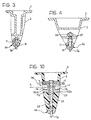
- Figures 3 and 4 are sections taken on the lines III-III and IV-IV of Figure 1, respectively, on an enlarged scale,
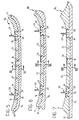
- Figures 5, 6 and 7 are longitudinal sections of three different embodiments of a detail of the skate of the preceding drawings, respectively,
- Figures 8 and 9 are partially-sectioned side elevational views of a second embodiment of the skate according to the invention,
- Figure 10 is a section taken on the line X-X of Figure 8, on an enlarged scale,
- Figures 11, 12 and 13 are sections taken on the lines XI-XI, XII-XII and XIII-XIII of Figures 5, 6, and 7, respectively.
-
- With reference to Figures 1 and 2, a first embodiment of an ice skate with interchangeable blades formed in accordance with the present invention is generally indicated 1.
- The skate 1 comprises a partially
hollow body 2 carrying an attachment flange 3 for fixing to the body of a boot 4, shown only partially in the drawings. On the opposite side to the attachment flange 3, the body has agroove 5 constituting a seat for housing a blade-holder 6a arranged for supporting arespective blade 7a and for being clamped against thebody 2, as will be described in detail below. - The skate 1 also comprises a plurality of sets of blades and respective blade-holders which are interchangeably replaceable in the
seat 5 of thebody 2. Figures 5 to 7 show three embodiments of sets of blades and respective blade-holders, generally indicated 8a, 8b and 8c, theblades blade 7a of the set 8a is particularly suitable for ice hockey since it is relatively short and noticeably thick (Figures 5 and 11). The blade 7b of the set 8b has geometrical characteristics of length, thickness and curvature designed appropriately for figure skating. Theblade 7c of theset 8c, on the other hand, is longer and thinner than the blades of the previous sets and is particularly suitable for speed skating. Eachset 8a, 8b, 8c comprises a respective blade-holder corresponding blade - An attachment portion, indicated 11, defined on each blade-
holder seat 5 of thebody 2 so as to render each blade and blade-holder set interchangeably replaceable on the body of the skate. It is intended that the skate 1 may be equipped with a plurality of blade and blade-holder sets of which each is formed in accordance with the skater's specific sporting requirements and of which thesets 8a, 8b and 8c represent only three examples. It should be noted that the plurality of sets may comprise blades having different geometrical configurations combined with identical blade-holders, for example, as in the sets 8a and 8b, or blades having different geometrical configurations combined with blade-holders of different shapes such as, for example, those constituting the twosets 8b and 8c. - The
attachment portion 11 of each blade-holder has a wedge-shaped cross section defined byopposed surfaces surface 13. The attachment portion is extended on the side opposite thesurface 13 by asecond portion 14 in which the corresponding blade is partially incorporated. Eachblade attachment portion 11 and defining, with the respective blade,recesses 16 which serve to improve the ability of the blade to grip the corresponding blade-holder.Shoulders 17 defined between theportions seat 5 of the body. - The inclination of the
surfaces attachment portion 11 is housed removably with a substantially shaped coupling in theseat 5 of the body which has opposed surfaces 18a, 18b extending from abase 19 and shaped in a corresponding manner in order to be engaged against the coupling surfaces of the attachment portion of the blade-holder. - Two respective stiffening elements, indicated 20, extend transversely in the
seat 5 to connect the opposed surfaces 18a, 18b. Thestiffening elements 20 are housed incorresponding recesses 21 in the blade-holder. - The skate 1 has a pair of rod-like ties, generally indicated 22 and 23, for clamping the blade of each blade and blade-holder set to the
body 2. The system for clamping the blade-holder to the body will be described with reference to theblade 7a of the set 8a, this description being intended to be applicable to every blade and blade-holder set. - Each
tie rod 24 housed for sliding in a hole in the body and carrying, at one of its ends, ahead 25 which can be housed releasably with a shaped coupling in acorresponding recess 26 formed in theappendage 15 of theblade 7a. The shape of therecess 26 is such as to form, with thehead 25, a coupling which is restrained in the direction of the axis of the rod. Thehead 25 is incorporated in the blade-holder 7a during its co-moulding on the blade. In this embodiment, eachset 8a, 8b, 8c has a pair ofties - At the opposite end to the
head 25, the rod has a threaded portion which can be screwed into a restraining element such as anut 27 which abuts a shoulder 28 of thebody 2. Holes, all indicated 29, are formed in the opposite sides of thebody 2 and are disposed adjacent the threaded ends of the ties when the blade-holder is mounted on the body, so that eachnut 27 is accessible from outside the body in order, for example, to be tightened by means of a spanner inserted through theholes 29 in order to apply the desired clamping load to the corresponding tie. Theholes 29 are preferably elliptical and elongate longitudinally relative to thebody 2. - It will be appreciated that, by virtue of the provision of the
holes 29 through which the restraining elements ornuts 27 are accessible from outside the body, the clamping or, alternatively, the removal of theblade holder 6a is effected without the need to remove the boot and without the need to have access to the inside of the boot in order to remove any means for the fixing of the blade. - The force generated in each
tie nut 27 is such as to bring about a corresponding clamping pressure between the mutual contact surfaces of the blade-holder 6a and of theseat 5. The load for clamping the blade- holder and hence the blade against thebody 2 is advantageously adjustable and controllable simply by the adjustment of the tensile force generated in theties holder 6a and of theseat 5 of the body is consequently also correspondingly easy to control. - In Figures 1 and 2, the skate 1 is shown in an operative position in which the blade-
holder 6a is housed in theseat 5 and theties respective nuts 27. As a result of the tightening of thenuts 27, theattachment portion 11 of the blade-holder is clamped by being wedged in theseat 5 of the body. This forced clamping by wedging ensures the stiffness and structural continuity of the blade-holder relative to the body. It should be noted that each tie extends substantially parallel to the direction of the application of the clamping load which urges the blade-holder and the body into mutual wedging engagement. This clamping load is therefore substantially equal to the entire tensile force generated in the tie by the tightening of the nuts. - With particular reference to Figures 8 to 10, a second embodiment of the skate of the present invention, in which details similar to those of the previous embodiment are indicated by the same reference numerals, is indicated 100.
- The
skate 100 differs from the skate of the previous embodiment in that it comprises an eccentric device, generally indicated 110 and described in detail below, for clamping the blade-holder to the body. - The
device 110 comprises, in the region of eachtie respective member 112 supported for rotation about an axis X between the sides of thebody 2. The end of anelement 113 forming an extension of thecorresponding rod 24 is articulated to eachmember 112 in an eccentric position relative to the axis X. Eachelement 113 has an axial threaded cavity into which the threaded portion of thecorresponding rod 24 is screwed. Theelement 113 is articulated about an axis Y parallel to the axis and spaced therefrom, with a predetermined eccentricity. - The
element 113 is partially housed in a recess in themember 112 in which tworespective surfaces 114a, 114b are formed at an inclination to one another, constituting abutment surfaces for thecorresponding tie - The
member 112 has opposedfaces 112a, 112b accessible from outside thebody 2 through respectivecircular holes 115 formed in the sides of the body. - A
respective recess 116 with a polygonal, for example, square cross-section is formed in eachface 112a, 112b for the engagement of a corresponding wrench, not shown, supplied with theskate 100 for rotating themember 112 about the axis X. - In Figure 9, the
skate 100 is shown in an inoperative position, that is, a position in which the blade-holder 6a is removed from theseat 5. In this position, eachmember 112 associated with therespective tie element 113 is interposed between the axis X and thehead 25 of the tie and therod 24 consequently projects from theseat 5 to enable the blade-holder to be removed from the body. It can be seen that, in this removal position, theelement 113 is in abutment with the abutment surface 114a which thus constitutes a limit for the angular travel permitted for themember 112. - Starting from the position of Figure 9, in order to clamp the blade-
holder 6a against thebody 2,. themember 112 is rotated in the direction of the arrow T of Figure 8 until theelement 113 is brought into abutment with theabutment surface 114b. In this position, the axis Y has moved, as a result of the eccentricity, to the opposite side of the axis X to thehead 25 of each tie, bringing about the sliding of the tie relative to the body which is necessary to move the blade-holder and clamp it in theseat 5. - By virtue of the adjustable coupling of the rod 24 (the threaded portion) with the
element 113, it is possible to adjust the length of the tie and consequently to vary the tensile stress produced therein by means of theeccentric device 110. The desired clamping load between the blade-holder and the body can therefore be applied and regulated by adjustment of thetie - It will also be appreciated that, by virtue of the above-described eccentric clamping device the same clamping load can easily be applied repeatably between the blade-holder and the body in a simple and reliable manner, each time the user wishes to replace a blade and blade-holder set of the skate.
- The invention thus solves the problem set, achieving many advantages.
- A first advantage is that blades of different geometrical configurations can be mounted on the same body so that the skate can be used for different skating disciplines.
- Moreover, by virtue of the provision of a blade-holder according to the invention, the height, and consequently the weight, of the blade of each set (blade and blade-holder) can advantageously be reduced; in particular, the blade can be limited purely to the portion intended for contact with the sole, the function of providing stiffness, particularly torsional stiffness, and the structural continuity of the blade relative to the body being entrusted to the wedge-shaped attachment portion.
- The reduction in the weight of the blade also advantageously permits the provision of sets of blades and respective blade-holders of relatively low overall weight, and having the desired geometrical configurations to satisfy the user's various skating requirements.
- Naturally, in order to satisfy contingent and specific requirements, an expert in the art may apply to the skate of the present invention many modifications and variations all of which, however, are included within the scope- of protection of the invention as defined by the following claims.
Claims (15)
- An ice skate with interchangeable blades, comprising a body (2) defining a seat (5) for housing a blade-holder to be clamped against the body, characterized in that the ice skate comprises a plurality of sets (8a, 8b, 8c) of blades (7a, 7b, 7c) and respective blade-holders (6a, 6b, 6c), in which at least the blades of the sets have different geometrical configurations, each set (8a, 8b, 8c) of the plurality being interchangeably replaceable in the seat (5) of the body (2) so that blades of different geometrical configurations can be mounted on the skate, preferably in order to use the skate for different disciplines.
- A skate according to Claim 1, in which the blade-holders (6a, 6b, 6c) of the sets (8a, 8b 8c) are co-moulded on the respective blades (7a, 7b, 7c).
- A skate according to Claim 2, in which each blade-holder comprises an attachment portion (11) to be housed and clamped in the seat (5) of the body, restraining means being provided for clamping the blade-holder to the body.
- A skate according to Claim 3, comprising at least one tie (22, 23) between the blade (7a, 7b, 7c) and the body (2), the restraining means being interposed between the at least one tie (22, 23) and the body (2) in order to clamp the corresponding blade-holder (6a, 6b, 6c) against the body (2) with the desired clamping load by means of the at least one tie (22, 23).
- A skate according to Claim 4, comprising, in the body, holes (29) affording access to the restraining means from outside the body (2) for the purpose of clamping the blade holder (6a, 6b, 6c) to the body (20) or, alternatively, removing it therefrom.
- A skate according to Claim 4 or Claim 5, in which there are two ties (22, 23) arranged in longitudinally opposed regions of the body (2).
- A skate according to claim 6, in which the ties (22, 23) extend in substantially parallel directions.
- A skate according to any one of Claims 3 to 7, in which the restraining means comprise a screw fixed to one of the respective tie (22, 23) and the body (2) and an internally-threaded member (27) engaged with the screw and abutting the other of the respective tie and the body, the male-and-female screw coupling being accessible from outside the body through the holes (29) in order to clamp the blade-holder (6a, 6b, 6c) to the body or, alternatively, to remove it therefrom.
- A skate according to any one of the Claims 4 to 7, in which the at least one tie (22, 23) is connected kinematically to the body and the restraining means comprise an eccentric clamping device (110) operatively connected to the tie in order to move it from an inoperative position in which the blade-holder (6a, 6b, 6c) is removed from the body, to an operative position in which the blade-holder (6a, 6b, 6c) is clamped against the body (2) as a result of the application of the clamping load by means of the tie (22, 23).
- A skate according to Claim 9, in which the clamping device comprises a member (112) supported for rotating about a first axis (X) on the body (2), the at least one tie (22, 23) being articulated to the member about a second axis (Y) parallel to and spaced from the first axis, the tie being movable between the inoperative and operative positions as a result of a rotation of the member (112) about the first axis (X), and the member being accessible from outside the body through the holes (29).
- A skate according to Claim 10, in which the at least one tie (22, 23) is fixed to the clamping device in an adjustable manner by means of a threaded coupling.
- A skate according to any one of Claims 9 to 11, in which there are two ties (22, 23) each of which is operatively connected to a respective eccentric clamping device (110).
- A skate according to any one of Claims 3 to 12, comprising shaped coupling means and counter-means on the attachment portion (11) of the blade-holder (6a, 6b, 6c) of each of the sets (8a, 8b, 8c) and in the seat (5) of the body (2), respectively, the means and the counter-means being mutually engageable in order to couple the blade-holder (6a, 6b, 6c) releasably to the body (2).
- A skate according to Claim 13, in which the shaped coupling means comprise a groove formed in the body and constituting the seat (5) and the shaped coupling counter-means comprise the attachment portion (11) of the blade-holder.
- A skate according to Claim 14, in which the attachment portion (11) of the blade-holder has a wedge-shaped cross-section.
Applications Claiming Priority (2)
| Application Number | Priority Date | Filing Date | Title |
|---|---|---|---|
| ITPD970159 | 1997-07-15 | ||
| IT97PD000159A IT1294789B1 (en) | 1997-07-15 | 1997-07-15 | INTERCHANGEABLE BLADE ICE SKATE |
Publications (2)
| Publication Number | Publication Date |
|---|---|
| EP0891792A1 EP0891792A1 (en) | 1999-01-20 |
| EP0891792B1 true EP0891792B1 (en) | 2003-03-05 |
Family
ID=11391866
Family Applications (1)
| Application Number | Title | Priority Date | Filing Date |
|---|---|---|---|
| EP98202235A Expired - Lifetime EP0891792B1 (en) | 1997-07-15 | 1998-07-03 | An ice skate with interchangeable blades |
Country Status (7)
| Country | Link |
|---|---|
| US (1) | US6485033B2 (en) |
| EP (1) | EP0891792B1 (en) |
| JP (1) | JPH11114126A (en) |
| AT (1) | ATE233585T1 (en) |
| CA (1) | CA2243195A1 (en) |
| DE (1) | DE69811784T2 (en) |
| IT (1) | IT1294789B1 (en) |
Families Citing this family (39)
| Publication number | Priority date | Publication date | Assignee | Title |
|---|---|---|---|---|
| US6932361B2 (en) * | 2000-06-26 | 2005-08-23 | Paul M. Steinhauser, Jr. | Skate with removable blade |
| US20020190487A1 (en) * | 2000-08-07 | 2002-12-19 | Blankenburg Karl Van | Goalie skate protective shell with removable blade |
| US6761363B2 (en) * | 2000-09-21 | 2004-07-13 | Hip Technologies, Llc | Runner and method of manufacture |
| EP1401544B1 (en) * | 2001-06-29 | 2010-09-15 | Mission Itech Hockey, Inc. | Skate chassis with pitch adjustment |
| GB0214031D0 (en) * | 2002-06-19 | 2002-07-31 | Hd Sports Ltd | Skate |
| WO2005079215A2 (en) * | 2004-02-03 | 2005-09-01 | Crow Blade Llc | A skate with an accessible runner securing system and methdos thereof |
| WO2006012432A2 (en) * | 2004-07-21 | 2006-02-02 | Rudolfh Robert K | Ice skate blade runner holder and blade runner and method of manufacture |
| US7036828B1 (en) * | 2004-10-15 | 2006-05-02 | Tournament Sports Marketing Inc. | Extruded light-weight figure skate blade holder with two part blade |
| CA2487626C (en) * | 2004-11-12 | 2013-01-15 | Dahlo, Alan Larry | Ice skate and ice skate blade thereof |
| DE102005004515B3 (en) * | 2005-01-31 | 2006-06-22 | Onyx-Systems Patentmanagement Gmbh | Ski sport device e.g. skating shoe, has base with t-blade runner holder at which two pairs of stop clip pushers are arranged in front and rear area for detachable connection and locking of t-blade runner |
| CA2619788A1 (en) * | 2005-08-18 | 2007-02-22 | Anatol Podolsky | Skate blades and methods and apparatus for affixing same |
| CA2540898C (en) * | 2006-03-23 | 2013-10-08 | Donald Allen Mcleod | Exercise weight for ice skates |
| US20080100008A1 (en) * | 2006-10-30 | 2008-05-01 | Fong-Chou Wan | Structural improvement for ice skate blade |
| CA2574753A1 (en) * | 2007-01-19 | 2008-07-19 | Multimatic Inc. | Replaceable blade skate |
| CA2682369C (en) | 2007-03-29 | 2012-07-03 | Sport Maska Inc. | Ice skate runner |
| US7866673B2 (en) * | 2007-07-20 | 2011-01-11 | Therma Blade Hockey Corp. | Heating arrangement for ice skate blades |
| EP2242548A4 (en) * | 2007-07-20 | 2013-05-22 | Therma Blade Inc | Ice skate blade and blade heating arrangement |
| US7866674B2 (en) * | 2007-09-07 | 2011-01-11 | Thermablade Hockey Corp. | Electrically heated ice skates |
| US20090273148A1 (en) * | 2008-05-01 | 2009-11-05 | Fong-Chou Wan | Manufacturing method for an ice skate blade |
| CN102105197B (en) * | 2008-07-25 | 2013-11-06 | 穆尔蒂马蒂奇公司 | Rotary retention latch for replaceable skate blade systems |
| CA2775510A1 (en) | 2011-10-18 | 2013-04-18 | Switchblade Sports (Bc) Corp. | Double-edged skate blade assembly and holder |
| EP3248659A3 (en) * | 2013-03-14 | 2018-01-10 | Bauer Hockey Corp. | Ice skate |
| WO2015048886A1 (en) * | 2013-10-04 | 2015-04-09 | Switchblade Sports (Bc) Corp. | Disposable double-edged skate blade |
| USD762275S1 (en) * | 2014-03-14 | 2016-07-26 | Bauer Hockey, Inc. | Ice skate blade holder |
| CA2909496C (en) | 2014-10-22 | 2020-07-07 | Easton Hockey, Inc. | Hockey skate including a one-piece frame with integral pedestals |
| US10406424B2 (en) | 2015-01-05 | 2019-09-10 | Bauer Hockey, Llc | Ice skate |
| US20160242496A1 (en) * | 2015-02-20 | 2016-08-25 | Kelly Barnes | Article of footwear |
| GB2526451B (en) * | 2015-07-30 | 2016-05-25 | Hd Sports Ltd | Ice skate blade arrangement |
| US11406157B2 (en) | 2016-02-09 | 2022-08-09 | Bauer Hockey, Llc | Skate or other footwear |
| US10376771B2 (en) | 2016-06-30 | 2019-08-13 | Bauer Hockey, Llc | Ice skate |
| USD949273S1 (en) | 2016-10-26 | 2022-04-19 | Bauer Hockey Llc. | Ice skate blade holder |
| US11071903B2 (en) * | 2016-12-22 | 2021-07-27 | Bauer Hockey Llc | Ice skate blade |
| US10974123B2 (en) * | 2016-12-22 | 2021-04-13 | Bauer Hockey Llc | Ice skate blade |
| CN113301825A (en) | 2018-10-29 | 2021-08-24 | 鲍尔曲棍球有限责任公司 | Skates or other shoes |
| US11420106B2 (en) * | 2019-09-24 | 2022-08-23 | Edward L. Altshuler | Adjustable hockey runner assembly |
| US12364919B2 (en) * | 2019-09-24 | 2025-07-22 | Edward L. Altshuler | Modular skate riser |
| CA3089463A1 (en) * | 2020-08-05 | 2022-02-05 | Kelly Riou | Off-ice training blade and skate |
| CN113318421B (en) * | 2021-05-26 | 2023-01-17 | 齐齐哈尔大学 | An ice blade mounting part for skating training |
| USD1040275S1 (en) | 2021-09-10 | 2024-08-27 | Edmond Goxhaj | Boot attachment for winter sport |
Family Cites Families (18)
| Publication number | Priority date | Publication date | Assignee | Title |
|---|---|---|---|---|
| DE78716C (en) * | H. hartig, Kändler i. S | Ice skate for running on trodden or parched snow | ||
| US2548391A (en) * | 1948-08-07 | 1951-04-10 | Joseph K Petrime | Convertible skate |
| US2874970A (en) * | 1957-05-31 | 1959-02-24 | Willis B Mall | Convertible skates |
| US4139209A (en) * | 1977-12-08 | 1979-02-13 | Humphreys Donald R | Adjustable shoe-skate assembly |
| US4351536A (en) * | 1980-08-15 | 1982-09-28 | Sandino Hector M | Ice skate attachment |
| US4379563A (en) * | 1981-03-24 | 1983-04-12 | Serge Arsenault | Auxiliary ice skate blade |
| US4932675A (en) * | 1986-11-28 | 1990-06-12 | Scott B. Olson | Skate assembly |
| US5314199A (en) * | 1992-04-14 | 1994-05-24 | O.S. Designs, Inc. | Convertible in-line roller skates |
| US5193827A (en) * | 1992-04-14 | 1993-03-16 | O.S. Designs, Inc. | Convertible in-line roller skates |
| DE4300053A1 (en) * | 1993-01-04 | 1994-07-07 | Samir Abou Kamal | Sports shoe with interchangeable base |
| US5524912A (en) * | 1993-03-01 | 1996-06-11 | Laub; Michael J. | All season skate |
| US5393077A (en) * | 1993-03-01 | 1995-02-28 | Wanous; Craig C. | All season skate |
| US5505467A (en) * | 1993-06-11 | 1996-04-09 | Built For Speed, Inc. | Adjustable skate support and bracket system |
| EP0765181B1 (en) * | 1994-06-14 | 1999-05-12 | Bauer Inc. | Ice skate |
| US5484148A (en) * | 1994-06-14 | 1996-01-16 | Canstar Sports Group Inc. | Skate blade assembly with reinforcement insert |
| US5595392A (en) * | 1995-07-31 | 1997-01-21 | Casillas; Anthony | In-line roller ice skate combination |
| CA2169106C (en) * | 1996-02-08 | 2005-09-13 | Fabio Venier | Replaceable blade skate |
| US5791662A (en) * | 1997-05-15 | 1998-08-11 | Searby; William | In-line, interchangeable roller-ice skate |
-
1997
- 1997-07-15 IT IT97PD000159A patent/IT1294789B1/en active IP Right Grant
-
1998
- 1998-07-03 AT AT98202235T patent/ATE233585T1/en not_active IP Right Cessation
- 1998-07-03 DE DE69811784T patent/DE69811784T2/en not_active Expired - Fee Related
- 1998-07-03 EP EP98202235A patent/EP0891792B1/en not_active Expired - Lifetime
- 1998-07-14 CA CA002243195A patent/CA2243195A1/en not_active Abandoned
- 1998-07-14 JP JP10199302A patent/JPH11114126A/en active Pending
- 1998-07-15 US US09/115,966 patent/US6485033B2/en not_active Expired - Fee Related
Also Published As
| Publication number | Publication date |
|---|---|
| DE69811784T2 (en) | 2004-02-12 |
| ATE233585T1 (en) | 2003-03-15 |
| IT1294789B1 (en) | 1999-04-15 |
| JPH11114126A (en) | 1999-04-27 |
| EP0891792A1 (en) | 1999-01-20 |
| US20020140186A1 (en) | 2002-10-03 |
| US6485033B2 (en) | 2002-11-26 |
| CA2243195A1 (en) | 1999-01-15 |
| DE69811784D1 (en) | 2003-04-10 |
| ITPD970159A1 (en) | 1999-01-15 |
Similar Documents
| Publication | Publication Date | Title |
|---|---|---|
| EP0891792A1 (en) | An ice skate with interchangeable blades | |
| EP0959963B1 (en) | Snowboard binding assembly with adjustable forward lean backplate | |
| AU662113B2 (en) | A foot transport device | |
| US5671939A (en) | Binding mount assembly for an alpine ski | |
| CN1147335C (en) | Skates with interchangeable blades | |
| US5941552A (en) | Adjustable snowboard binding apparatus and method | |
| US5226673A (en) | Braking assembly and method | |
| US20070164530A1 (en) | Skateboard truck with single-pin, pivotal, reversible attachment between axel and base plate, and means of improving a user's shredding capabilities through use of the skateboard truck with single-pin, pivotal attachment between axel and base plate | |
| CA2144862A1 (en) | In-line skate braking assembly and method | |
| US6481724B1 (en) | Adapter for converting in-line roller skates to ice skates | |
| US6189911B1 (en) | Snow board binding system | |
| US8191918B2 (en) | Device for adjusting ski binding height for improved balance | |
| US4379563A (en) | Auxiliary ice skate blade | |
| US5522609A (en) | Adjustable skate brake | |
| US6003882A (en) | Customizable skate with removable wheel hangers | |
| WO1993005854A1 (en) | In-line skate brake system | |
| NL8800917A (en) | Adjustable boot height norwegian ice skate - has blade held in aluminium strip clamped by jaws bridge with slotted side pieces and adjusting screw | |
| EP0717652A1 (en) | Adjustable ice skate | |
| RU2057565C1 (en) | Skate for ice-board | |
| US3626529A (en) | Water skiing device | |
| CA1124758A (en) | Auxiliary ice skate blade | |
| CA2024812C (en) | Improved ski binding support | |
| EP0810011A2 (en) | A brake for skates, particularly in-line roller skates and a skate equipped with the brake | |
| WO2004009191A1 (en) | Roller skate | |
| ITMI982433A1 (en) | ATTACHMENT FIXING DEVICE ON SNOW BOARDS AND SIMILAR. |
Legal Events
| Date | Code | Title | Description |
|---|---|---|---|
| PUAI | Public reference made under article 153(3) epc to a published international application that has entered the european phase |
Free format text: ORIGINAL CODE: 0009012 |
|
| AK | Designated contracting states |
Kind code of ref document: A1 Designated state(s): AT CH DE FR GB IT LI SE |
|
| AX | Request for extension of the european patent |
Free format text: AL;LT;LV;MK;RO;SI |
|
| 17P | Request for examination filed |
Effective date: 19990113 |
|
| AKX | Designation fees paid |
Free format text: AT CH DE FR GB IT LI SE |
|
| AXX | Extension fees paid |
Free format text: LT PAYMENT 19990403;RO PAYMENT 19990403;SI PAYMENT 19990403 |
|
| RBV | Designated contracting states (corrected) |
Designated state(s): AT CH DE FR GB IT LI SE |
|
| GRAH | Despatch of communication of intention to grant a patent |
Free format text: ORIGINAL CODE: EPIDOS IGRA |
|
| GRAH | Despatch of communication of intention to grant a patent |
Free format text: ORIGINAL CODE: EPIDOS IGRA |
|
| GRAA | (expected) grant |
Free format text: ORIGINAL CODE: 0009210 |
|
| AK | Designated contracting states |
Designated state(s): AT CH DE FR GB IT LI SE |
|
| AX | Request for extension of the european patent |
Extension state: LT RO SI |
|
| PG25 | Lapsed in a contracting state [announced via postgrant information from national office to epo] |
Ref country code: FR Free format text: LAPSE BECAUSE OF NON-PAYMENT OF DUE FEES Effective date: 20030305 |
|
| REG | Reference to a national code |
Ref country code: GB Ref legal event code: FG4D |
|
| REG | Reference to a national code |
Ref country code: CH Ref legal event code: EP |
|
| REF | Corresponds to: |
Ref document number: 69811784 Country of ref document: DE Date of ref document: 20030410 Kind code of ref document: P |
|
| PG25 | Lapsed in a contracting state [announced via postgrant information from national office to epo] |
Ref country code: SE Free format text: LAPSE BECAUSE OF FAILURE TO SUBMIT A TRANSLATION OF THE DESCRIPTION OR TO PAY THE FEE WITHIN THE PRESCRIBED TIME-LIMIT Effective date: 20030605 |
|
| PG25 | Lapsed in a contracting state [announced via postgrant information from national office to epo] |
Ref country code: GB Free format text: LAPSE BECAUSE OF NON-PAYMENT OF DUE FEES Effective date: 20030703 Ref country code: AT Free format text: LAPSE BECAUSE OF NON-PAYMENT OF DUE FEES Effective date: 20030703 |
|
| PG25 | Lapsed in a contracting state [announced via postgrant information from national office to epo] |
Ref country code: LI Free format text: LAPSE BECAUSE OF NON-PAYMENT OF DUE FEES Effective date: 20030731 Ref country code: CH Free format text: LAPSE BECAUSE OF NON-PAYMENT OF DUE FEES Effective date: 20030731 |
|
| LTIE | Lt: invalidation of european patent or patent extension |
Effective date: 20030305 |
|
| PLBE | No opposition filed within time limit |
Free format text: ORIGINAL CODE: 0009261 |
|
| STAA | Information on the status of an ep patent application or granted ep patent |
Free format text: STATUS: NO OPPOSITION FILED WITHIN TIME LIMIT |
|
| EN | Fr: translation not filed | ||
| PG25 | Lapsed in a contracting state [announced via postgrant information from national office to epo] |
Ref country code: DE Free format text: LAPSE BECAUSE OF NON-PAYMENT OF DUE FEES Effective date: 20040203 |
|
| 26N | No opposition filed |
Effective date: 20031208 |
|
| GBPC | Gb: european patent ceased through non-payment of renewal fee |
Effective date: 20030703 |
|
| REG | Reference to a national code |
Ref country code: CH Ref legal event code: PL |
|
| PG25 | Lapsed in a contracting state [announced via postgrant information from national office to epo] |
Ref country code: IT Free format text: LAPSE BECAUSE OF NON-PAYMENT OF DUE FEES Effective date: 20050703 |