EP0890281B1 - A home location register for a mobile telecommunications network - Google Patents
A home location register for a mobile telecommunications network Download PDFInfo
- Publication number
- EP0890281B1 EP0890281B1 EP96909317A EP96909317A EP0890281B1 EP 0890281 B1 EP0890281 B1 EP 0890281B1 EP 96909317 A EP96909317 A EP 96909317A EP 96909317 A EP96909317 A EP 96909317A EP 0890281 B1 EP0890281 B1 EP 0890281B1
- Authority
- EP
- European Patent Office
- Prior art keywords
- database
- location register
- home location
- handler
- bus
- Prior art date
- Legal status (The legal status is an assumption and is not a legal conclusion. Google has not performed a legal analysis and makes no representation as to the accuracy of the status listed.)
- Expired - Lifetime
Links
- 238000012423 maintenance Methods 0.000 claims description 24
- 230000004044 response Effects 0.000 claims description 12
- 238000000638 solvent extraction Methods 0.000 claims description 4
- 230000003213 activating effect Effects 0.000 claims description 2
- 230000003362 replicative effect Effects 0.000 claims description 2
- 238000000034 method Methods 0.000 description 12
- 239000010410 layer Substances 0.000 description 9
- 101150042248 Mgmt gene Proteins 0.000 description 7
- 230000008569 process Effects 0.000 description 7
- 230000010076 replication Effects 0.000 description 7
- 238000005192 partition Methods 0.000 description 6
- 230000001360 synchronised effect Effects 0.000 description 4
- 238000012369 In process control Methods 0.000 description 2
- 230000008901 benefit Effects 0.000 description 2
- 230000008859 change Effects 0.000 description 2
- 238000010276 construction Methods 0.000 description 2
- 210000004544 dc2 Anatomy 0.000 description 2
- 238000004190 ion pair chromatography Methods 0.000 description 2
- 238000011084 recovery Methods 0.000 description 2
- 101000597193 Homo sapiens Telethonin Proteins 0.000 description 1
- 108010076504 Protein Sorting Signals Proteins 0.000 description 1
- 102100035155 Telethonin Human genes 0.000 description 1
- 238000013459 approach Methods 0.000 description 1
- 210000004271 bone marrow stromal cell Anatomy 0.000 description 1
- 238000004891 communication Methods 0.000 description 1
- 238000000354 decomposition reaction Methods 0.000 description 1
- 238000010586 diagram Methods 0.000 description 1
- 239000000284 extract Substances 0.000 description 1
- 230000006870 function Effects 0.000 description 1
- 230000000977 initiatory effect Effects 0.000 description 1
- 239000002346 layers by function Substances 0.000 description 1
- 230000007246 mechanism Effects 0.000 description 1
- 230000004048 modification Effects 0.000 description 1
- 238000012986 modification Methods 0.000 description 1
- 238000012544 monitoring process Methods 0.000 description 1
- 230000011664 signaling Effects 0.000 description 1
- 238000012546 transfer Methods 0.000 description 1
Images




Classifications
-
- H—ELECTRICITY
- H04—ELECTRIC COMMUNICATION TECHNIQUE
- H04W—WIRELESS COMMUNICATION NETWORKS
- H04W8/00—Network data management
- H04W8/02—Processing of mobility data, e.g. registration information at HLR [Home Location Register] or VLR [Visitor Location Register]; Transfer of mobility data, e.g. between HLR, VLR or external networks
- H04W8/04—Registration at HLR or HSS [Home Subscriber Server]
-
- H—ELECTRICITY
- H04—ELECTRIC COMMUNICATION TECHNIQUE
- H04W—WIRELESS COMMUNICATION NETWORKS
- H04W8/00—Network data management
- H04W8/02—Processing of mobility data, e.g. registration information at HLR [Home Location Register] or VLR [Visitor Location Register]; Transfer of mobility data, e.g. between HLR, VLR or external networks
- H04W8/06—Registration at serving network Location Register, VLR or user mobility server
-
- H—ELECTRICITY
- H04—ELECTRIC COMMUNICATION TECHNIQUE
- H04W—WIRELESS COMMUNICATION NETWORKS
- H04W24/00—Supervisory, monitoring or testing arrangements
- H04W24/04—Arrangements for maintaining operational condition
Definitions
- the invention relates to a home location register (HLR) for a digital mobile telecommunications system.
- HLR home location register
- the HLR has had a distributed configuration located at the mobile switching centres.
- the HLR became complex and, at times, unworkable.
- This HLR comprises a number of access processors connected to a bus. Each access processor stores all permanent subscriber data and a subset of the temporary subscriber data such as visitor location data.
- the HLR includes a link device which allocates queries by polling and possibly re-direction of access requests over the bus.
- a further problem is that the polling and re-direction signals transmitted from the link device cause a large degree of bus traffic and possibly slower response times.
- HLR HLR which is "future proof" whereby it may be easily modified to accommodate increasing numbers of subscribers in a simple and flexible manner. Further, there is a need for a HLR which is more fault tolerant, and for a HLR which is simpler to maintain and update.
- a mobile telecommunications network home location register comprising:-
- This arrangement provides for simple upgrading and also simple fault tracing and maintenance generally.
- the access processor and database capacities may be independently increased.
- the invention also allows fast access and minimises bus traffic by avoiding the need for network access processor polling.
- the maintenance processor comprises means for updating the directory service. This is a simple method of achieving consistency across the HLR.
- each item of subscriber data is stored in an active location on one memory database and also in a shadow location on a different memory database.
- the directory service of the network access processor identifies the database server having access to the memory database storing the active locations for each item of subscriber data.
- each database server comprises means for dynamically updating the shadow locations upon updating the associated active locations.
- each database server comprises means for updating the shadow locations according to one of a plurality of pre-stored schemes according to desired performance and security levels.
- each network access processor comprises means for performing a transaction-orientated commit when updating a memory database.
- each network access processor comprises means for uploading bus status and error signals to the maintenance processor.
- the maintenance processor comprises means for partitioning the subscriber data between memory databases by control of the database servers.
- the maintenance processor is directly connected to the storage database and comprises means for accessing the memory databases via the database servers to update the storage database.
- the maintenance processor may comprise means for replicating the subscriber data in the storage database.
- the home location register further comprises an auxiliary processor connected to the bus and comprising means for accessing subscriber data in the memory databases via the bus and the database servers.
- each database server comprises a core connected to a database handler, in turn connected to the memory database and to a plurality of external handlers connected to the bus.
- the core comprises a plurality of finite state machine dialogue handlers, each for performing core operations of a single transaction at one time.
- an external handler comprises means for activating a dialogue handler upon receipt of a transaction request, and means for identifying by way of a parameter value the transaction and the dialogue handler.
- the external handler, the dialogue handler and the database handler comprise means for identifying subscriber data retrieved in the transaction as an object having an identifier and a server memory location.
- the dialogue handler comprises means for identifying the external handler for a particular transaction by way of a temporary identifier.
- each database server comprises means for identifying dirty subscriber data items, namely those which have not been updated to the storage database.
- each database server comprises means for determining if any item has been updated to the storage database if a request is received from the maintenance processor for a subsequent item to be updated.
- the dirty items are identified by a flag within each item.
- each database server preferably comprises means for immediately changing the flag to a clean status after transmitting the item to the maintenance processor to update the storage database, and for setting it again to a dirty status if a negative response is received from the maintenance processor.
- a mobile telecommunications system 1 incorporating a home location register (HLR) 10.
- the system 1 comprises a signalling system 2 of the 2 SS7 type.
- a number of mobile switching centres (MSC) 3 are connected to the SS7 and each is associated with a number of base transceiver stations (BTS) 4.
- BTS base transceiver stations
- Each BTS receives signals from mobile subscribers (MS) 5.
- MS mobile subscribers
- the high speed bus 11 is a pair of parallel serial links which can operate at 10 to 100 Mbits/s.
- the second link provides redundancy.
- the network access processor layer 12 comprises a number of network access processors (NAPs) 20, each having a directory service 21.
- the MAPS 20 are connected to the bus 11 by links 22.
- the database server layer 13 comprises in this embodiment two database servers 25, each directly connected to an active memory database (DB) 26 and a shadow memory database (DB) 27 and being connected to the bus 11 by links 28.
- DB active memory database
- DB shadow memory database
- the operations and maintenance processor layer 14 comprises an operations and maintenance processor (OMP) 30 having a subscriber disk database 31.
- OMP operations and maintenance processor
- the HLR 10 comprises an auxiliary processor 40.
- Interconnection of the elements via the bus 11 is through inter-process communication (IPC) interfaces which overlie the standard operating system IPCs, such as UNIXTM IPCs.
- IPC inter-process communication
- the components of the HLR 10 may be remotely or locally arranged - the bus 11 being provided according to the requirements.
- Each of the DBSs 25 manages a subset of all subscriber data and all NAPs 20 have access to all of the DBSs 25.
- the NAPs 20 In order for the NAPs 20 to be totally independent.of the DBSs 25, they include the directory service 21 which comprises a RAM-based table which contains:-
- the shadow locations for active locations of one memory database 26 are all on the same shadow memory database 27.
- the OMP 30 dynamically updates the directory services 21 with the active location data so that when a NAP 21 is to perform a transaction, it routes the request to the correct DBS 25 the first time. This helps to provide a fast response within the HLR 10 as seen by the MSCs 3 by minimising bus traffic.
- the DBS 25 automatically updates the shadow memory database 27 via the bus 11.
- the transactions are performed by the NAP 20 as a transaction-oriented commit whereby the DBS 25 does not commit a data update until the NAP 20 ends the transaction. This allows error recovery during complex operations. If the active DB is inaccessible, the NAP 20 accesses the shadow DB instead, this being indicated in the directory service 21.
- each NAP 20 comprises an SS7 stack as specified and this is connected to a Mobile Application Part - Provider (MAP-P) 55, in turn connected to a Mobile Application Part - User (MAP-User) 60.
- the MAP-P comprises a core 56, a Portable TCAP 27 and a MAP interface 58.
- the MAP-User 60 comprises a core 61, an Authentication Centre (AuC) interface 62, a DBS interface 63, a MAP interface 64, and a management interface 65.
- AuC Authentication Centre
- the NAP 20 uses the management interface 65 to upload bus status and error signals to the OMP 30. This is important because it causes bus errors to be immediately flagged and the necessary error recovery operations performed. This is achieved by monitoring resources and port/interface integrity.
- Each DBS 25 also uploads error signals to the OMP 30.
- each DBS 25 comprises a core 70 having a distributor 71, dialogue handlers 72, and a threshold handler 73. These components together communicate through management 74, client 75, outgoing request 76, and database 77 signal interfaces to various handlers.
- a database handler 80 provides access to the databases 26 and 27.
- the DBS 25 also comprises system services 85.
- the DBS 25 is designed using functional decomposition methodology and specification and description language (SDL) and is hardware independent.
- the DBS 25 is on a HP-UXTM operating system.
- the dialogue handlers 72 are implemented as state machines activated by the distributor 71. Each dialogue handler instance handles only one transaction at any one time, and the limit of simultaneous transactions performed by all handlers 72 within the core 70 is monitored and controlled by the threshold handler 73.
- the management handler 82 allows access by the OMP 30 and any other management/maintenance machines connected to the bus 11. It is through this handler that the DBS 25 is configured and start/stop and alarm signals are handled.
- the client handler 83 allows access by clients generally, including the NAPS 20 and the OMP 30.
- the outgoing request handler 84 allows the DBS 25 access the shadow memory database (DB) 27. There is only one shadow DB 27 for each DBS 25.
- the OMP 30 transmits subscriber data to the active DB 26 of each DBS 25 according to a desired partitioning strategy.
- the data may be partitioned for three DBSs 25 as follows:- Partition A Partition B Partition C 40% of subscribers 40% of subscribers 20% of subscribers Shadow for Partition C. Shadow for Partition A. Shadow for Partition B.
- any desired partitioning scheme may be used. It is also possible to put all subscriber data on a single DBS 30. The important point is that there is complete flexibility.
- the DBs 26, 27 are in RAM, however, all data is also stored in the disk database 31 directly connected to the OMP 30, on which it is replicated for additional fault tolerance. Data in an active DB 26 which has not been updated to the disk database 31 is referred to as "dirty" data and the manner of updating to change the status to "clean” is described below.
- External management systems may have access to the OMP 30 either directly or via the bus 11 to:-
- the auxiliary processor 40 may be an external management system, or alternatively a management reporting processor. Because of the overall configuration of the HLR 10, such processors may be easily connected.
- the distributor 71 operates to activate a dialogue handler 72 upon receipt of a client request and messages are then transmitted through the client handler 83 directly, by-passing the distributor 71.
- Most client operations will cause the initiation of a database transaction, and some will cause the shadow DB 27 to be updated.
- a dialogue handler 72 manages these operations. An instance of a dialogue handler 72 is created for such a transaction and it is then responsible for the full transaction, and it exits when the transaction is complete.
- the database handler 80 interfaces between the core 70 and the DBs 26, 27 and has a portable database API to provide it with a level of abstraction from the DBs 26, 27.
- the actual data retrieved from the DB 26 is not integrated into the SDL, but is instead referred to as an object having an area of memory within the core 70 and an identifier. The address of this area is passed to the database handler 80, and it is maintained by the external handler involved and may be accessed by the core 70 and the database handler 80.
- Table 1 defines the database signal interface 77 between the core 70 and the database handler 80.
- a transaction is referred to as a "dialogue" or "process”.
- Database Signal Interface 77 Signal Name Description Sent By DB_BEGIN_TRANS Begin a dialogue; inform the DB Handler of the Dialogue Handler's SDL process id.
- Core DB_BEGIN_ACK Inform Core of database transaction id
- Core DB_READ Read data for instance of Object Core DB_READLOCK Lock and Read data for instance of Object Core DB_READFIRST Read data for first object in list Core DB_READNEXT Read data for next object in list Core DB_WRITE Perform Write (update/create/delete/ clean/dirty) on instance of Object Unlock if KeepLock is false (if applicable) Dirty as specified by Dirty Flag (if applicable)
- DB_LOCK Lock data for instance of Object Core DB_UNLOCK Unlock data for instance of Object Core DB_DATA
- Core DB_DIRTY_DATA Returns type and contents of dirty record.
- the signal DB_BEGIN_TRANS notifies the database handler 80 of the start of a dialogue (transaction).
- DB_COMMIT and DB_ABORT cause the dialogue to end.
- Cursor requests are dealt with by the signals DB_READFIRST and DB_READNEXT, responses arrive in a DB_DATA signal.
- DB_READLOCK is equivalent to using the signal DB_LOCK followed by DB_READ.
- the former is provided so that possible performance advantages of combining locking and reading can be realised.
- Each new instance of a dialogue handler 72 is recognised by a unique identifier.
- the database handler 80 uses this identifier to ensure that replies are directed to the correct core handler 71.
- the database handler 80 provides a transaction identifier to the core.
- the interface 77 is independent of the structure of the actual data and an object is represented by a type identifier which is the object identifier and a pointer to an area of DBS operating system memory sufficiently large to hold the object.
- the DB_WRITE signal has an operator parameter specifying the type of write operation to be performed.
- Objects that are capable of being updated to the disk database 31 have a dirty field set by the client.
- the DB_CLEAN signal resets this fields value to CLEAN.
- Dirty records are accessed sequentially and it is necessary to specify a value for a sequence flag in dirty record requests.
- the valid values are FIRST, NEXT, and LAST.
- Responses from the database handler 80 contain a result field.
- Valid values are SUCCESS, FAILURE, NOTFOUND, and LOCKED.
- the following Table 2 describes the client signal interface 75.
- Each new client transaction is recognised by a unique identifier.
- the core uses this identifier to ensure that replies are directed to the correct client handler process.
- a parameter used in the CL_BEGIN_TRANS signal informs the core 70 of the kind of client issuing the request.
- the valid values for this parameter are OMP, Peer, and Network.
- the outgoing request interface 76 allows replication to the peer (shadow) DB 27 and synchronisation from a peer DB on restart.
- the identity of the peer DB 27 is configurable by the OMP 30, as described above and the configuration is stored on a file which is read at start-up.
- An important aspect of the invention is the fact that the nature of the replication is configurable, and three different schemes are illustrated in Figs. 6(a), 6(b) and 6(c).
- Fig. 6(a) shows a scheme whereby a database update and acknowledgement to the client only take place after replication has been acknowledged. This is the most secure scheme.
- Fig. 6(b) illustrates a scheme where the DBS 25 does not wait for replication acknowledgement before writing to the memory DB 26. It does not acknowledge to the client until the replication acknowledgement is received. This provides an excellent level of security and also a good response time.
- the DBS 25 does not wait for the replication acknowledgement before either updating the database or sending an acknowledgement to the client. This provides a very fast response to the client.
- Outgoing Request Signal Interface 76 Signal Name Description Sent By REP_WRITE Replicate a write (update/create/ delete/clean/dirty) operation.
- Core REP_ACK Acknowledges replication request
- Core SYNC_DIRTY_DATA Returns type and contents of dirty record. "Last Element" will be true if there are no more dirty records.
- the interface 76 is designed to be independent of the structure of the actual objects being read or written as the core 70 is not concerned with such details.
- an object is just represented by a type identifier (i.e. number) and a pointer to a location in memory that is sufficiently large to hold this object.
- the management handler 82 provides the following functionality:-
- the interface 74 is defined using SDL signals. All signals sent by the management handler 82 to the core 70 are handled by the distributor 71.
- Management signal interface 74 MANAGEMENT SIGNAL INTERFACE 74 Signal Name Description Sent By ENABLE Causes Core DBS to connect to its database and external handlers so that synchronisation can begin.
- Mgmt Management Handler
- ENABLE_ACK Acknowledges initialisation of Core; this tells the manager that the OMP can now begin to send synchronisation records to the DBS.
- SYNC Tells DBS to begin synchronisation with another DBS.
- Mgmt SHUTDOWN_ACK Acknowledges shutdown of Core Core DISABLE causes the Core to free all its resources and close the database.
- Mgmt DISABLE_ACK Acknowledges disabling of Core Core REASSESS Tells the DBS that the configuration data has been changed on-line.
- Mgmt OVERLOAD Informs the Management Handler that the number of dialogues has exceeded gv_dbs_global.dial_upper_threshold.
- Core OVERLOAD_CLEAR Informs the Management Handler that the number of dialogues has returned within gv_dbs_global.dial_lower_threshold.
- Core BUSY Informs the Management Handler that the number of dialogues is at gv_dbs_ global.max_dialogues
- Core EVENT Allows the Core DBS to notify the Management Handler of a problem.
- the core 70 generates events to be passed to the management handler 82 indicating programming errors, congestion, etc. These consist of an event number and a list of appropriate parameters indicating, for example, if the error is recoverable.
- dirty records are records that have been updated, created or deleted from the network but that have not been updated in the disk database on the OMP.
- an OMP update is under control of a process on the OMP 30.
- This process requests a dirty record from the DBS which replies with an acknowledgement incorporating the dirty record.
- the OMP extracts the data from the acknowledgement from the DBS, updates the disk database 31 and then requests the next dirty record.
- the dirty record becomes clean if it is successfully updated in the OMP disk database 31. This acknowledgement is incorporated in the next request from the OMP to the DBS in the PrevResult field, for performance reasons. If this result is not successful, the record remains marked as dirty and the next request is processed.
- the rate of data transfer is under control of the OMP process, so an OMP-update can be operated at a rate that is as slow as is required.
- An OMP update can be made continuous if the OMP-update process issues a CL_DIRTY_REQ(first) immediately after receiving a CL_DIRTY_DATA(last).
- the DBS must now update its database with all the records marked as dirty on the peer database as these have not been updated to the OMP and therefore have not been downloaded from the OMP. It sends a request to the peer database server asking for the first dirty record in the database. The peer server will send the dirty record data in a response. The database server then asks for the next record and this continues until a single pass through the database has completed. The peer server then sends a notification indicating that it has completed sending dirty records. The dirty record sequence flag is used in this operation, as with an OMP update.
- the peer database server does not change the status of the dirty records during this procedure.
- the memory databases are each accessed by a single channel only (the associated DBS 25) accesses are much more efficiently handled than heretofore as control is simpler.
- the DBSs are accessed directly via the bus 11, there is a large degree of versatility as subscriber expansion is not directly linked to the NAPs 20.
- the DBS structure is modular, again providing flexibility. This has been achieved using the simple transaction, client, and object, and dialogue handler identification method described.
- NAPs 20 have directory services 21. These ensure that bus traffic is minimised by allowing the NAP 20 have immediate access to the relevant DBS 25.
- bus of the HLR has been described as entirely external in nature, it is envisaged that it could be partly internal within a hardware system.
- a NAP 20 and a DBS 25 could reside on a single hardware platform, in which case that particular NAP would access the DBS via an internal bus. Any other NAPs would access that DBS as described above via the external bus.
- the important point is that for each memory database, there is only one access route, namely, its associated DBS and a bus linking it with clients in the HLR.
Landscapes
- Engineering & Computer Science (AREA)
- Databases & Information Systems (AREA)
- Computer Networks & Wireless Communication (AREA)
- Signal Processing (AREA)
- Information Retrieval, Db Structures And Fs Structures Therefor (AREA)
Abstract
Description
- The invention relates to a home location register (HLR) for a digital mobile telecommunications system. Traditionally, the HLR has had a distributed configuration located at the mobile switching centres. However, as systems increased in size with increasing numbers of subscribers, the HLR became complex and, at times, unworkable.
- There has therefore been a trend towards separating the HLR from the mobile switching centres and providing a more centralised configuration. An example is that described in British Patent Specification No. GB 2269962. This HLR comprises a number of access processors connected to a bus. Each access processor stores all permanent subscriber data and a subset of the temporary subscriber data such as visitor location data. The HLR includes a link device which allocates queries by polling and possibly re-direction of access requests over the bus.
- A problem with such an arrangement is that the databases are dedicated to particular access processors and therefore linear growth in subscriber numbers is directly linked to access processors. This can lead to lack of fault tolerance, to complexity, and to the need for additional control functions. It is also expensive.
- A further problem is that the polling and re-direction signals transmitted from the link device cause a large degree of bus traffic and possibly slower response times.
- There is therefore a need for a HLR which is "future proof" whereby it may be easily modified to accommodate increasing numbers of subscribers in a simple and flexible manner. Further, there is a need for a HLR which is more fault tolerant, and for a HLR which is simpler to maintain and update.
- According to the invention, there is provided a mobile telecommunications network home location register comprising:-
- a high speed bus;
- at least two database servers, each directly connected to a memory database of subscriber data and connected to the bus;
- a maintenance processor having operator interfaces, being connected to the bus, and comprising means for accessing subscriber data on the memory databases via the bus and the database servers; and
- a storage database, characterised in that,
-
- This arrangement provides for simple upgrading and also simple fault tracing and maintenance generally. The access processor and database capacities may be independently increased. Further, there is universal access to subscriber data through a single channel for each database, namely the database server. This provides for effective control of subscriber data access.
- The invention also allows fast access and minimises bus traffic by avoiding the need for network access processor polling. Preferably, the maintenance processor comprises means for updating the directory service. This is a simple method of achieving consistency across the HLR.
- In one embodiment, each item of subscriber data is stored in an active location on one memory database and also in a shadow location on a different memory database. Preferably, the directory service of the network access processor identifies the database server having access to the memory database storing the active locations for each item of subscriber data. In another embodiment, each database server comprises means for dynamically updating the shadow locations upon updating the associated active locations. These features provide for simple maintenance of shadow databases with little bus traffic.
- Preferably, each database server comprises means for updating the shadow locations according to one of a plurality of pre-stored schemes according to desired performance and security levels.
- In one embodiment, each network access processor comprises means for performing a transaction-orientated commit when updating a memory database.
- In another embodiment, each network access processor comprises means for uploading bus status and error signals to the maintenance processor.
- In a further embodiment, the maintenance processor comprises means for partitioning the subscriber data between memory databases by control of the database servers.
- In another embodiment, the maintenance processor is directly connected to the storage database and comprises means for accessing the memory databases via the database servers to update the storage database. For redundancy, the maintenance processor may comprise means for replicating the subscriber data in the storage database.
- In one embodiment, the home location register further comprises an auxiliary processor connected to the bus and comprising means for accessing subscriber data in the memory databases via the bus and the database servers.
- In one embodiment, each database server comprises a core connected to a database handler, in turn connected to the memory database and to a plurality of external handlers connected to the bus.
- Preferably, the core comprises a plurality of finite state machine dialogue handlers, each for performing core operations of a single transaction at one time.
- In another embodiment, an external handler comprises means for activating a dialogue handler upon receipt of a transaction request, and means for identifying by way of a parameter value the transaction and the dialogue handler.
- Preferably, the external handler, the dialogue handler and the database handler comprise means for identifying subscriber data retrieved in the transaction as an object having an identifier and a server memory location.
- In one embodiment, the dialogue handler comprises means for identifying the external handler for a particular transaction by way of a temporary identifier.
- In a further embodiment, each database server comprises means for identifying dirty subscriber data items, namely those which have not been updated to the storage database. Preferably, each database server comprises means for determining if any item has been updated to the storage database if a request is received from the maintenance processor for a subsequent item to be updated. Preferably, the dirty items are identified by a flag within each item.
- In the latter embodiment, each database server preferably comprises means for immediately changing the flag to a clean status after transmitting the item to the maintenance processor to update the storage database, and for setting it again to a dirty status if a negative response is received from the maintenance processor.
- The invention will be more clearly understood from the following description of some embodiments thereof, given by way of example only with reference to the accompanying drawings in which;-
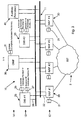
- Fig. 1 is a general schematic representation of a mobile telecommunications system incorporating a home location register of the invention;
- Fig. 2 is an overview schematic representation of the home location register of the invention;
- Fig. 3 is a more detailed representation of the home location register;
- Fig. 4 is a schematic representation of a network access processor of the home location register;
- Fig. 5 is a schematic representation of a database server of the home location register; and
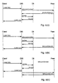
- Figs. 6(a), (b) and (c) are signal sequence diagrams of the database server.
-
- Referring to the drawings, and initially to Fig. 1, there is shown a
mobile telecommunications system 1 incorporating a home location register (HLR) 10. Thesystem 1 comprises asignalling system 2 of the 2 SS7 type. A number of mobile switching centres (MSC) 3 are connected to the SS7 and each is associated with a number of base transceiver stations (BTS) 4. Each BTS receives signals from mobile subscribers (MS) 5. At this level, such a system is conventional. - Referring now to Figs. 2 to 6, the
HLR 10 of the invention is described in detail. At the heart of the HLR 10, there is a high-speed bus 11 which is connected directly to three functional layers as follows:- - a network
access processor layer 12 connected to the SS7, - a
database server layer 13, and - an operations and
maintenance processor layer 14 accessible by administration operators. -
- The
high speed bus 11 is a pair of parallel serial links which can operate at 10 to 100 Mbits/s. The second link provides redundancy. - It will be clear from the general schematic of Fig. 2 that an important aspect of the
HLR 10 is that thedatabase server layer 13 is separate from the networkaccess processor layer 12. It will also be clear that all routing of signals between layers is through thebus 11, which acts as a central router. - Referring in particular to Fig. 3, the network
access processor layer 12 comprises a number of network access processors (NAPs) 20, each having adirectory service 21. TheMAPS 20 are connected to thebus 11 bylinks 22. - The
database server layer 13 comprises in this embodiment twodatabase servers 25, each directly connected to an active memory database (DB) 26 and a shadow memory database (DB) 27 and being connected to thebus 11 bylinks 28. An important point is that all accesses to a memory database are through a single channel, namely the associated DBS. - The operations and
maintenance processor layer 14 comprises an operations and maintenance processor (OMP) 30 having asubscriber disk database 31. - Finally, the
HLR 10 comprises anauxiliary processor 40. Interconnection of the elements via thebus 11 is through inter-process communication (IPC) interfaces which overlie the standard operating system IPCs, such as UNIX™ IPCs. - The components of the
HLR 10 may be remotely or locally arranged - thebus 11 being provided according to the requirements. - Each of the
DBSs 25 manages a subset of all subscriber data and allNAPs 20 have access to all of theDBSs 25. In order for theNAPs 20 to be totally independent.of theDBSs 25, they include thedirectory service 21 which comprises a RAM-based table which contains:- - primary data access keys;
- identification of the server associated with the memory database having the active location for an item of subscriber data; and
- identification of the server associated with the memory database having the shadow location for an item of subscriber data.
-
- In this embodiment, the shadow locations for active locations of one
memory database 26 are all on the sameshadow memory database 27. TheOMP 30 dynamically updates thedirectory services 21 with the active location data so that when aNAP 21 is to perform a transaction, it routes the request to thecorrect DBS 25 the first time. This helps to provide a fast response within theHLR 10 as seen by theMSCs 3 by minimising bus traffic. Once a transaction is performed with the relevantactive memory database 26, theDBS 25 automatically updates theshadow memory database 27 via thebus 11. The transactions are performed by theNAP 20 as a transaction-oriented commit whereby theDBS 25 does not commit a data update until theNAP 20 ends the transaction. This allows error recovery during complex operations. If the active DB is inaccessible, theNAP 20 accesses the shadow DB instead, this being indicated in thedirectory service 21. - Referring in particular to Fig. 4, the structure of each
NAP 20 is illustrated. It comprises an SS7 stack as specified and this is connected to a Mobile Application Part - Provider (MAP-P) 55, in turn connected to a Mobile Application Part - User (MAP-User) 60. The MAP-P comprises a core 56, aPortable TCAP 27 and aMAP interface 58. The MAP-User 60 comprises a core 61, an Authentication Centre (AuC)interface 62, aDBS interface 63, aMAP interface 64, and amanagement interface 65. This modular construction allows simple modification and upgrading, and also simpler operation. TheNAP 20 uses themanagement interface 65 to upload bus status and error signals to theOMP 30. This is important because it causes bus errors to be immediately flagged and the necessary error recovery operations performed. This is achieved by monitoring resources and port/interface integrity. EachDBS 25 also uploads error signals to theOMP 30. - Referring to Fig. 5, each
DBS 25 comprises a core 70 having adistributor 71,dialogue handlers 72, and athreshold handler 73. These components together communicate throughmanagement 74,client 75,outgoing request 76, anddatabase 77 signal interfaces to various handlers. Adatabase handler 80 provides access to thedatabases bus 11. These include amanagement handler 82, aclient handler 83 and anoutgoing request handler 84. TheDBS 25 also comprises system services 85. - The
DBS 25 is designed using functional decomposition methodology and specification and description language (SDL) and is hardware independent. In this embodiment, theDBS 25 is on a HP-UX™ operating system. Thedialogue handlers 72 are implemented as state machines activated by thedistributor 71. Each dialogue handler instance handles only one transaction at any one time, and the limit of simultaneous transactions performed by allhandlers 72 within thecore 70 is monitored and controlled by thethreshold handler 73. - The
management handler 82 allows access by theOMP 30 and any other management/maintenance machines connected to thebus 11. It is through this handler that theDBS 25 is configured and start/stop and alarm signals are handled. - The
client handler 83 allows access by clients generally, including theNAPS 20 and theOMP 30. - The
outgoing request handler 84 allows theDBS 25 access the shadow memory database (DB) 27. There is only oneshadow DB 27 for eachDBS 25. - At start-up, the following sequence takes place within a DBS 25:-
- (a) The
management handler 82 enables the database andclient handlers client handler 83 is set to an "OMP-synchronising" state at which it will only accept connections from theOMP 30. - (b) The
OMP 30 sends an ENABLE message to thecore 70 via themanagement handler 82. - (c) The
distributor 71 is enabled and an ENABLE-ACK signal is sent back to theOMP 30. - (d) The
OMP 30 connects to theDBS 25 and starts OMP synchronisation. - (e) The
OMP 30 sends an UNLOCK message to thecore 70 via themanagement handler 82. - (f) The
core 70 unlocks theclient handler 83, allowing all clients (such as NAPs 20) to connect. It then sends an UNLOCK-ACK to themanagement handler 82. - (g) The
OMP 30 sends a PEER-SYNC message to thecore 70 via themanagement handler 82. This instructs theDBS 25 to synchronise with itsparticular shadow DB 27. - (h) The
core 70 enables theoutgoing request handler 84 and begins to send peer synchronisation requests to theshadow DB 27. When this is complete, it sends a PEER-SYNC-ACK signal to themanagement handler 82. -
- After start-up, the
OMP 30 transmits subscriber data to theactive DB 26 of eachDBS 25 according to a desired partitioning strategy. For example, the data may be partitioned for threeDBSs 25 as follows:-Partition A Partition B Partition C 40% of subscribers 40% of subscribers 20% of subscribers Shadow for Partition C. Shadow for Partition A. Shadow for Partition B. - Because the
DBSs 25 and theDBs NAPs 20 and directly addressable by theOMP 30 via thebus 11, any desired partitioning scheme may be used. It is also possible to put all subscriber data on asingle DBS 30. The important point is that there is complete flexibility. - The
DBs disk database 31 directly connected to theOMP 30, on which it is replicated for additional fault tolerance. Data in anactive DB 26 which has not been updated to thedisk database 31 is referred to as "dirty" data and the manner of updating to change the status to "clean" is described below. - External management systems may have access to the
OMP 30 either directly or via thebus 11 to:- - (i) perform a remote log-in to gain access to the HLR management system,
- (ii) provide a standard protocol for management of the HLR, or
- (iii) provide a proprietary control for management of the HLR, e.g. operator man machine language (MML).
-
- The
auxiliary processor 40 may be an external management system, or alternatively a management reporting processor. Because of the overall configuration of theHLR 10, such processors may be easily connected. - Referring again to Fig. 5, the
distributor 71 operates to activate adialogue handler 72 upon receipt of a client request and messages are then transmitted through theclient handler 83 directly, by-passing thedistributor 71. Most client operations will cause the initiation of a database transaction, and some will cause theshadow DB 27 to be updated. Adialogue handler 72 manages these operations. An instance of adialogue handler 72 is created for such a transaction and it is then responsible for the full transaction, and it exits when the transaction is complete. - The
database handler 80 interfaces between the core 70 and theDBs DBs DB 26 is not integrated into the SDL, but is instead referred to as an object having an area of memory within thecore 70 and an identifier. The address of this area is passed to thedatabase handler 80, and it is maintained by the external handler involved and may be accessed by thecore 70 and thedatabase handler 80. - The
database handler 80 and theexternal handlers 81 communicate with the core 70 by interfaces 74-77. The following Table 1 defines thedatabase signal interface 77 between the core 70 and thedatabase handler 80. A transaction is referred to as a "dialogue" or "process".Database Signal Interface 77Signal Name Description Sent By DB_BEGIN_TRANS Begin a dialogue; inform the DB Handler of the Dialogue Handler's SDL process id. Core DB_BEGIN_ACK Inform Core of database transaction id Db Handler DB_COMMIT End a dialogue, committing database changes Core DB_ABORT Abort a dialogue, with rollback if possible. Core DB_READ Read data for instance of Object Core DB_READLOCK Lock and Read data for instance of Object Core DB_READFIRST Read data for first object in list Core DB_READNEXT Read data for next object in list Core DB_WRITE Perform Write (update/create/delete/ clean/dirty) on instance of Object
Unlock if KeepLock is false (if applicable)
Dirty as specified by Dirty Flag (if applicable)DB_LOCK Lock data for instance of Object Core DB_UNLOCK Unlock data for instance of Object Core DB_DATA Returns pointer to requested data
"Last Element" will be true if this is the last response to a cursor requestDb Handler DB_ACK Acknowledges a request Db Handler DB_DIRTY_REQ Get a dirty record
Clean = true => dirty flag to be unset;
Clean = false=> dirty flag to remain.Core DB_DIRTY_DATA Returns type and contents of dirty record.
"Last Element" will be true if there are no more dirty records.Db Handler - The signal DB_BEGIN_TRANS notifies the
database handler 80 of the start of a dialogue (transaction). DB_COMMIT and DB_ABORT cause the dialogue to end. - Cursor requests are dealt with by the signals DB_READFIRST and DB_READNEXT, responses arrive in a DB_DATA signal.
- Using the signal DB_READLOCK is equivalent to using the signal DB_LOCK followed by DB_READ. The former is provided so that possible performance advantages of combining locking and reading can be realised.
- Each new instance of a
dialogue handler 72 is recognised by a unique identifier. Thedatabase handler 80 uses this identifier to ensure that replies are directed to thecorrect core handler 71. Likewise, thedatabase handler 80 provides a transaction identifier to the core. - As stated above, the
interface 77 is independent of the structure of the actual data and an object is represented by a type identifier which is the object identifier and a pointer to an area of DBS operating system memory sufficiently large to hold the object. - The DB_WRITE signal has an operator parameter specifying the type of write operation to be performed.
- Objects that are capable of being updated to the
disk database 31 have a dirty field set by the client. The DB_CLEAN signal resets this fields value to CLEAN. - Dirty records are accessed sequentially and it is necessary to specify a value for a sequence flag in dirty record requests. The valid values are FIRST, NEXT, and LAST.
- Responses from the
database handler 80 contain a result field. Valid values are SUCCESS, FAILURE, NOTFOUND, and LOCKED. - The following Table 2 describes the
client signal interface 75.Client Signal Interface Signal Name Description Sent By CL_BEGIN_TRANS Begin a dialogue; Inform Core of client transaction Id Client H CL_COMMIT End a dialogue Client H CL_ABORT Abort a dialogue, with rollback if possible. Client H CL_READ Read data for instance of Object Client H CL_READLOCK Lock instance of Object and read it Client H CL_READFIRST Read data for first object in list Client H CL_READNEXT Read data for next object in list Client H CL_R_UPDATE Update Object and replicate to peer
Unlock if KeepLock is false Dirty as specified by DirtyFlagClient H CL_NR_UPDATE Update Object
Unlock if KeepLock is false Dirty as specified by DirtyFlagClient H CL_R_CREATE Create Object; replicate to peer
Dirty as specified by DirtyFlagClient H
(Client Handler)CL_NR_CREATE Create Object
Dirty as specified by DirtyFlagClient H CL_R_DELETE Delete Object and replicate to peer Client H CL_NR_DELETE Delete Object
Unlock if KeepLock is false Dirty as specified by DirtyFlagClient H CL_LOCK Lock data for instance of Object Client H CL_UNLOCK Unlock data for instance of Object Client H CL_R_CLEAN Clean dirty object; i.e. reset dirty flag to zero. Replicate to peer Client H CL_NR CLEAN Clean dirty object; i.e. reset dirty flag to zero. Client H CL_DATA Returns pointer to requested data.
"Last Element" will be true if this is the last response to a cursor request.Core CL_ACK Acknowledges a request Core CL_DIRTY_REQ Get a dirty record
Clean = true => dirty flag to be unset;
Clean = false => dirty flag to remain.Client H CL_DIRTY_DATA Returns type and contents of dirty record.
"Last Element" will be true if there are no more dirty records.Client H - Each new client transaction is recognised by a unique identifier. The core uses this identifier to ensure that replies are directed to the correct client handler process.
- A parameter used in the CL_BEGIN_TRANS signal informs the
core 70 of the kind of client issuing the request. The valid values for this parameter are OMP, Peer, and Network. - The
outgoing request interface 76 allows replication to the peer (shadow)DB 27 and synchronisation from a peer DB on restart. The identity of thepeer DB 27 is configurable by theOMP 30, as described above and the configuration is stored on a file which is read at start-up. An important aspect of the invention is the fact that the nature of the replication is configurable, and three different schemes are illustrated in Figs. 6(a), 6(b) and 6(c). - Fig. 6(a) shows a scheme whereby a database update and acknowledgement to the client only take place after replication has been acknowledged. This is the most secure scheme.
- Fig. 6(b) illustrates a scheme where the
DBS 25 does not wait for replication acknowledgement before writing to thememory DB 26. It does not acknowledge to the client until the replication acknowledgement is received. This provides an excellent level of security and also a good response time. - In the scheme shown in Fig. 6(c), the
DBS 25 does not wait for the replication acknowledgement before either updating the database or sending an acknowledgement to the client. This provides a very fast response to the client. - Regarding the outgoing
request signal interface 76, this is defined in Table 3 using SDL signals as follows.Outgoing Request Signal Interface 76Signal Name Description Sent By REP_WRITE Replicate a write (update/create/ delete/clean/dirty) operation. Core REP_ACK Acknowledges replication request Outgoing Req. Handler SYNC_DIRTY_REQ Get a dirty record
Clean = true => dirty flag to be unset;
Clean = false => dirty flag to remain.Core SYNC_DIRTY_DATA Returns type and contents of dirty record.
"Last Element" will be true if there are no more dirty records.Outgoing Req. Handler - The
interface 76 is designed to be independent of the structure of the actual objects being read or written as thecore 70 is not concerned with such details. Thus an object is just represented by a type identifier (i.e. number) and a pointer to a location in memory that is sufficiently large to hold this object. - The
management handler 82 provides the following functionality:- - Startup and shutdown of the other handlers and the
core 70. - Initialisation and on-line configuration of parameters, e.g. transaction limits, debugging flags, etc.
- Statistics reporting.
- Forward of alarms/events to the
OMP 30. - The
interface 74 is defined using SDL signals. All signals sent by themanagement handler 82 to the core 70 are handled by thedistributor 71. - The following is a description of the management signal interface 74:
MANAGEMENT SIGNAL INTERFACE 74Signal Name Description Sent By ENABLE Causes Core DBS to connect to its database and external handlers so that synchronisation can begin. Mgmt (Management Handler) ENABLE_ACK Acknowledges initialisation of Core; this tells the manager that the OMP can now begin to send synchronisation records to the DBS.
Result=true=>successful initialisation Result=false=>unsuccessful initialisationCore SYNC Tells DBS to begin synchronisation with another DBS.
Clean=true=>clean dirty records on synchMgmt SYNC_ACK Tells Management Handler that peer synchronisation has completed Core UNLOCK Causes the Core DBS to move into the UNLOCKED state in which it will accept dialogues Mgmt UNLOCK_ACK Acknowledges unlocking of Core Core LOCK Causes the Core DBS to forcibly finish all outstanding dialogues and be moved to the LOCKED state. All outstanding dialogues are aborted. Mgmt LOCK_ACK Acknowledges locking of Core Core SHUTDOWN Causes the Core DBS to deny any further incoming dialogues. Currently outstanding dialogues are allowed to finish. When all are finished, the Core DBS moves to the LOCKED state. Mgmt SHUTDOWN_ACK Acknowledges shutdown of Core Core DISABLE Causes the Core to free all its resources and close the database. Mgmt DISABLE_ACK Acknowledges disabling of Core Core REASSESS Tells the DBS that the configuration data has been changed on-line. Mgmt OVERLOAD Informs the Management Handler that the number of dialogues has exceeded gv_dbs_global.dial_upper_threshold. Core OVERLOAD_CLEAR Informs the Management Handler that the number of dialogues has returned within gv_dbs_global.dial_lower_threshold. Core BUSY Informs the Management Handler that the number of dialogues is at gv_dbs_ global.max_dialogues Core EVENT Allows the Core DBS to notify the Management Handler of a problem. Core - The
core 70 generates events to be passed to themanagement handler 82 indicating programming errors, congestion, etc. These consist of an event number and a list of appropriate parameters indicating, for example, if the error is recoverable. - As stated above, dirty records are records that have been updated, created or deleted from the network but that have not been updated in the disk database on the OMP.
- There are two uses of dirty records:
- 1. To distinguish which records have to be updated to
the
OMP disk database 31. - 2. To complete synchronisation of a memory database after it has been synchronised with the OMP at start-up.
-
- Regarding
use 1. above, an OMP update is under control of a process on theOMP 30. This process requests a dirty record from the DBS which replies with an acknowledgement incorporating the dirty record. The OMP extracts the data from the acknowledgement from the DBS, updates thedisk database 31 and then requests the next dirty record. - The dirty record becomes clean if it is successfully updated in the
OMP disk database 31. This acknowledgement is incorporated in the next request from the OMP to the DBS in the PrevResult field, for performance reasons. If this result is not successful, the record remains marked as dirty and the next request is processed. - There remains the problem of a dirty record being updated again from the NAP after the acknowledgement to the OMP has been sent, but before the next OMP request (incorporating the disk update acknowledgement) has been received. The DBS needs a mechanism to allow it to know that such a record should not be marked as clean in these circumstances.
- This is solved by clearing the dirty bit before receiving the piggy-backed acknowledgement from the OMP. If the acknowledgement from the OMP is negative, the dirty bit can be set, thus marking the record as dirty again. If the record has been updated from the network (NAP) it will be marked as dirty in the usual way. This approach means there will be a single update of the dirty bit under normal conditions.
- The rate of data transfer is under control of the OMP process, so an OMP-update can be operated at a rate that is as slow as is required.
- An OMP update can be made continuous if the OMP-update process issues a CL_DIRTY_REQ(first) immediately after receiving a CL_DIRTY_DATA(last).
- Regarding
use 2. above, after a DBS has been synchronised with the OMP disk database, it may be necessary for it to be synchronised with its peer DBS. This will be necessary if the peer DBS has been servicing client requests while the DBS was being synchronised with the OMP disk database. - The DBS must now update its database with all the records marked as dirty on the peer database as these have not been updated to the OMP and therefore have not been downloaded from the OMP. It sends a request to the peer database server asking for the first dirty record in the database. The peer server will send the dirty record data in a response. The database server then asks for the next record and this continues until a single pass through the database has completed. The peer server then sends a notification indicating that it has completed sending dirty records. The dirty record sequence flag is used in this operation, as with an OMP update.
- The peer database server does not change the status of the dirty records during this procedure.
- In summary, by virtue of the fact that the memory databases are each accessed by a single channel only (the associated DBS 25) accesses are much more efficiently handled than heretofore as control is simpler. Because the DBSs are accessed directly via the
bus 11, there is a large degree of versatility as subscriber expansion is not directly linked to theNAPs 20. The automatic updating to theshadow DB 27, the updating via theOMP 30 to thedisk database 31, and the manner in which the components of eachDBS 25 operate all lead to a large degree of fault tolerance. It has been found that the manner in which the data is handled and addressed only as an object is particularly effective at ensuring errors do not arise and a fast response to clients is provided. The DBS structure is modular, again providing flexibility. This has been achieved using the simple transaction, client, and object, and dialogue handler identification method described. - Another important advantage of the invention arises because the
NAPs 20 havedirectory services 21. These ensure that bus traffic is minimised by allowing theNAP 20 have immediate access to therelevant DBS 25. - While the bus of the HLR has been described as entirely external in nature, it is envisaged that it could be partly internal within a hardware system. For example, a
NAP 20 and aDBS 25 could reside on a single hardware platform, in which case that particular NAP would access the DBS via an internal bus. Any other NAPs would access that DBS as described above via the external bus. The important point is that for each memory database, there is only one access route, namely, its associated DBS and a bus linking it with clients in the HLR. - The invention is not limited to the embodiments described, but may be varied in construction and detail within the scope of the appended claims.
the home location register further comprises at least one network access processor connected to the bus, each network access processor comprising means for interfacing with a network and for performing transactions requested via the network by accessing data on the memory databases via the bus and the database servers, and
each network access processor comprises a directory service indicating location of subscriber data on the memory databases.
Claims (21)
- A mobile telecommunications network home location register comprising:characterised in that,a high speed bus (11);at least two database servers (25), each directly connected to a memory database (26, 27) of subscriber data and connected to the bus;a maintenance processor (30) having operator interfaces, being connected to the bus, and comprising means for accessing subscriber data on the memory databases via the bus and the database servers; anda storage database (31),
the home location register further comprises at least one network access processor (20) connected to the bus (11), each network access processor comprising means for interfacing with a network (2) and for performing transactions requested via the network (2) by accessing data on the memory databases via the bus (11) and the database servers (25), and
each network access processor (20) comprises a directory service indicating location of subscriber data on the memory databases (26, 27). - A home location register as claimed in claim 1, wherein the maintenance processor (30) comprises means for updating the directory service.
- A home location register as claimed in any preceding claim, wherein each item of subscriber data is stored in an active location on one memory database (26) and also in a shadow location on a different memory database (27).
- A home location register as claimed in claim 3 in combination with claim 2, wherein the directory service of each network access processor (20) identifies the database server (25) having access to the memory database (26) storing the active locations for each item of subscriber data.
- A home location register as claimed in claim 4, wherein each database server (25) comprises means for dynamically updating the shadow locations (27) upon updating the associated active locations (26).
- A home location register as claimed in claim 5, wherein each database server (25) comprises means for updating the shadow locations (27) according to one of a plurality of pre-stored schemes according to desired performance and security levels.
- A home location register as claimed in any preceding claim, wherein each network access processor (20) comprises means for performing a transaction-oriented commit when updating a memory database.
- A home location register as claimed in any preceding claim, wherein each network access processor (20) comprises means for uploading bus status and error signals to the maintenance processor.
- A home location register as claimed in any preceding claim, wherein the maintenance processor (30) comprises means for partitioning the subscriber data between memory databases by control of the database servers (25).
- A home location register as claimed in any preceding claim, wherein the maintenance processor (30) is directly connected to the storage database (31) and comprises means for accessing the memory databases (26, 27) via the database servers (25) to update the storage database.
- A home location register as claimed in any preceding claim, wherein the maintenance processor (30) comprises means for replicating the subscriber data in the storage database (31).
- A home location register as claimed in any preceding claim, further comprising an auxiliary processor (40) connected to the bus and comprising means for accessing subscriber data in the memory databases (26, 27) via the bus (11) and the database servers (25).
- A home location register as claimed in any preceding claim, wherein each database server (25) comprises a core (70) connected to a database handler (90), in turn connected to the memory database (26, 27) and to a plurality of external handlers (82-84) connected to the bus (11).
- A home location register as claimed in claim 13, wherein the core (70) comprises a plurality of finite state machine dialogue handlers (71-73), each for performing core operations of a single transaction at one time.
- A home location register as claimed in claim 14, wherein an external handler (74-76) comprises means for activating a dialogue handler (72) upon receipt of a transaction request, and means for identifying by way of a parameter value the transaction and the dialogue handler.
- A home location register as claimed in claims 14 or 15, wherein the external handler (82-84), the dialogue handler (72), and the database handler (80) each comprise means for identifying subscriber data retrieved in the transaction as an object having an identifier and a server memory location.
- A home location register as claimed in claim 16, wherein the dialogue handler (72) comprises means for identifying the external handler (82-84) for a particular transaction by way of a temporary identifier.
- A home location register as claimed in any preceding claim, wherein each database server (25) comprises means for identifying dirty subscriber data items, namely those which have not been updated to the storage database.
- A home location register as claimed in claim 18, wherein each database server (25) comprises means for determining if any item has been updated to the storage database (31) if a request is received from the maintenance processor (30) for a subsequent item to be updated.
- A home location register as claimed in claim 19, wherein the dirty items are identified by a flag within each item.
- A home location register as claimed in claim 20, wherein each database server (25) comprises means for immediately changing the flag to a clean status after transmitting the item to the maintenance processor (30) to update the storage database, and for setting it again to a dirty status if a negative response is received from the maintenance processor.
Applications Claiming Priority (2)
| Application Number | Priority Date | Filing Date | Title |
|---|---|---|---|
| CA002250103A CA2250103A1 (en) | 1996-03-28 | 1996-03-28 | A home location register for a mobile telecommunications network |
| PCT/IE1996/000015 WO1997036446A1 (en) | 1996-03-28 | 1996-03-28 | A home location register for a mobile telecommunications network |
Publications (2)
| Publication Number | Publication Date |
|---|---|
| EP0890281A1 EP0890281A1 (en) | 1999-01-13 |
| EP0890281B1 true EP0890281B1 (en) | 2002-09-25 |
Family
ID=25680561
Family Applications (1)
| Application Number | Title | Priority Date | Filing Date |
|---|---|---|---|
| EP96909317A Expired - Lifetime EP0890281B1 (en) | 1996-03-28 | 1996-03-28 | A home location register for a mobile telecommunications network |
Country Status (4)
| Country | Link |
|---|---|
| EP (1) | EP0890281B1 (en) |
| AU (1) | AU720380B2 (en) |
| CA (1) | CA2250103A1 (en) |
| WO (1) | WO1997036446A1 (en) |
Families Citing this family (4)
| Publication number | Priority date | Publication date | Assignee | Title |
|---|---|---|---|---|
| GB2329790A (en) * | 1997-09-25 | 1999-03-31 | Dsc Telecom Lp | Maintaining information concerning subscriber terminals within a call routing system of a telecommunications system |
| ATE410891T1 (en) * | 1999-12-23 | 2008-10-15 | Markport Ltd | WIRELESS MOBILE SERVICES FACILITY |
| KR100594132B1 (en) * | 2000-01-28 | 2006-06-28 | 삼성전자주식회사 | Interface device and method of code location multiple access mobile telephone network system home location register with improved signal processing performance |
| CN100388805C (en) * | 2003-11-10 | 2008-05-14 | 华为技术有限公司 | A data disaster recovery method for home location register |
Family Cites Families (1)
| Publication number | Priority date | Publication date | Assignee | Title |
|---|---|---|---|---|
| GB2269962B (en) * | 1992-08-19 | 1996-04-10 | Northern Telecom Ltd | Communications systems |
-
1996
- 1996-03-28 CA CA002250103A patent/CA2250103A1/en not_active Abandoned
- 1996-03-28 AU AU52864/96A patent/AU720380B2/en not_active Expired
- 1996-03-28 EP EP96909317A patent/EP0890281B1/en not_active Expired - Lifetime
- 1996-03-28 WO PCT/IE1996/000015 patent/WO1997036446A1/en not_active Ceased
Also Published As
| Publication number | Publication date |
|---|---|
| AU720380B2 (en) | 2000-06-01 |
| CA2250103A1 (en) | 1997-10-02 |
| WO1997036446A1 (en) | 1997-10-02 |
| EP0890281A1 (en) | 1999-01-13 |
| AU5286496A (en) | 1997-10-17 |
Similar Documents
| Publication | Publication Date | Title |
|---|---|---|
| US5528677A (en) | System for providing communications services in a telecommunications network | |
| US7890463B2 (en) | Apparatus and method for a distributed storage global database | |
| JPH0323752A (en) | Transfer of subscriber automatically executed between electronic message service system in network | |
| EP1577776B1 (en) | Method and apparatus for data synchronization in a distributed data base system | |
| US6871068B1 (en) | Database updated in a mobile communication system | |
| JP5054065B2 (en) | Database apparatus, database alignment system, and database alignment method | |
| US20020059316A1 (en) | Method and apparatus for improving message availability in a subsystem which supports shared message queues | |
| US6360095B1 (en) | Home location register for a mobile telecommunications network | |
| US6445905B1 (en) | Method of preventing data inconsistency between master exchange data and backup exchange data | |
| AU720380B2 (en) | A home location register for a mobile telecommunications network | |
| KR100346342B1 (en) | Mobility in Telecommunication Networks | |
| JP4830081B2 (en) | Wireless mobility service platform | |
| KR100194771B1 (en) | Subscription management device for personal communication service (PCS) and its method | |
| KR100194763B1 (en) | Personal communication service subscriber information processing device and method | |
| IE80764B1 (en) | A home location register for a mobile telecommunications network | |
| IES960258A2 (en) | A home location register for a mobile telecommunications network | |
| EP1391131B1 (en) | Data element information management in a network environment | |
| US5966713A (en) | Method for determining the contents of a restoration log | |
| KR20030053679A (en) | Data processing and management of user interface server in network management system | |
| KR0174603B1 (en) | How to restore the database of the exchange | |
| JP3708582B2 (en) | Data processing system and terminal information automatic setting method | |
| JPH0973410A (en) | Distributed database management method | |
| MXPA01000537A (en) | Subscriber creation and deletion interface between a customer administrative system and database network elements of a communications network | |
| JPH08205234A (en) | Mobile terminal information management method in network and management system thereof | |
| KR19990017083A (en) | Database of global electronic exchangers Global transaction management method |
Legal Events
| Date | Code | Title | Description |
|---|---|---|---|
| PUAI | Public reference made under article 153(3) epc to a published international application that has entered the european phase |
Free format text: ORIGINAL CODE: 0009012 |
|
| 17P | Request for examination filed |
Effective date: 19980924 |
|
| AK | Designated contracting states |
Kind code of ref document: A1 Designated state(s): AT BE CH DE DK ES FI FR GB GR IE IT LI LU MC NL PT SE Kind code of ref document: A1 Designated state(s): AT BE CH DE DK ES FI FR GB GR IT LI LU MC NL PT SE |
|
| 17Q | First examination report despatched |
Effective date: 19991206 |
|
| RAP1 | Party data changed (applicant data changed or rights of an application transferred) |
Owner name: MARKPORT LIMITED |
|
| RIC1 | Information provided on ipc code assigned before grant |
Free format text: 7H 04Q 7/38 A |
|
| RTI1 | Title (correction) |
Free format text: A HOME LOCATION REGISTER FOR A MOBILE TELECOMMUNICATIONS NETWORK |
|
| GRAG | Despatch of communication of intention to grant |
Free format text: ORIGINAL CODE: EPIDOS AGRA |
|
| GRAG | Despatch of communication of intention to grant |
Free format text: ORIGINAL CODE: EPIDOS AGRA |
|
| GRAH | Despatch of communication of intention to grant a patent |
Free format text: ORIGINAL CODE: EPIDOS IGRA |
|
| RBV | Designated contracting states (corrected) |
Designated state(s): AT BE CH DE DK ES FI FR GB GR IT LI LU MC NL PT SE |
|
| GRAH | Despatch of communication of intention to grant a patent |
Free format text: ORIGINAL CODE: EPIDOS IGRA |
|
| GRAA | (expected) grant |
Free format text: ORIGINAL CODE: 0009210 |
|
| AK | Designated contracting states |
Kind code of ref document: B1 Designated state(s): AT BE CH DE DK ES FI FR GB GR IT LI LU MC NL PT SE |
|
| PG25 | Lapsed in a contracting state [announced via postgrant information from national office to epo] |
Ref country code: NL Free format text: LAPSE BECAUSE OF FAILURE TO SUBMIT A TRANSLATION OF THE DESCRIPTION OR TO PAY THE FEE WITHIN THE PRESCRIBED TIME-LIMIT Effective date: 20020925 Ref country code: LI Free format text: LAPSE BECAUSE OF FAILURE TO SUBMIT A TRANSLATION OF THE DESCRIPTION OR TO PAY THE FEE WITHIN THE PRESCRIBED TIME-LIMIT Effective date: 20020925 Ref country code: IT Free format text: LAPSE BECAUSE OF FAILURE TO SUBMIT A TRANSLATION OF THE DESCRIPTION OR TO PAY THE FEE WITHIN THE PRESCRIBED TIME-LIMIT;WARNING: LAPSES OF ITALIAN PATENTS WITH EFFECTIVE DATE BEFORE 2007 MAY HAVE OCCURRED AT ANY TIME BEFORE 2007. THE CORRECT EFFECTIVE DATE MAY BE DIFFERENT FROM THE ONE RECORDED. Effective date: 20020925 Ref country code: GR Free format text: LAPSE BECAUSE OF FAILURE TO SUBMIT A TRANSLATION OF THE DESCRIPTION OR TO PAY THE FEE WITHIN THE PRESCRIBED TIME-LIMIT Effective date: 20020925 Ref country code: FR Free format text: LAPSE BECAUSE OF FAILURE TO SUBMIT A TRANSLATION OF THE DESCRIPTION OR TO PAY THE FEE WITHIN THE PRESCRIBED TIME-LIMIT Effective date: 20020925 Ref country code: FI Free format text: LAPSE BECAUSE OF FAILURE TO SUBMIT A TRANSLATION OF THE DESCRIPTION OR TO PAY THE FEE WITHIN THE PRESCRIBED TIME-LIMIT Effective date: 20020925 Ref country code: CH Free format text: LAPSE BECAUSE OF FAILURE TO SUBMIT A TRANSLATION OF THE DESCRIPTION OR TO PAY THE FEE WITHIN THE PRESCRIBED TIME-LIMIT Effective date: 20020925 Ref country code: BE Free format text: LAPSE BECAUSE OF FAILURE TO SUBMIT A TRANSLATION OF THE DESCRIPTION OR TO PAY THE FEE WITHIN THE PRESCRIBED TIME-LIMIT Effective date: 20020925 Ref country code: AT Free format text: LAPSE BECAUSE OF FAILURE TO SUBMIT A TRANSLATION OF THE DESCRIPTION OR TO PAY THE FEE WITHIN THE PRESCRIBED TIME-LIMIT Effective date: 20020925 |
|
| REF | Corresponds to: |
Ref document number: 225116 Country of ref document: AT Date of ref document: 20021015 Kind code of ref document: T |
|
| REG | Reference to a national code |
Ref country code: GB Ref legal event code: FG4D |
|
| REG | Reference to a national code |
Ref country code: CH Ref legal event code: EP |
|
| REF | Corresponds to: |
Ref document number: 69623998 Country of ref document: DE Date of ref document: 20021031 |
|
| PG25 | Lapsed in a contracting state [announced via postgrant information from national office to epo] |
Ref country code: SE Free format text: LAPSE BECAUSE OF FAILURE TO SUBMIT A TRANSLATION OF THE DESCRIPTION OR TO PAY THE FEE WITHIN THE PRESCRIBED TIME-LIMIT Effective date: 20021225 Ref country code: DK Free format text: LAPSE BECAUSE OF FAILURE TO SUBMIT A TRANSLATION OF THE DESCRIPTION OR TO PAY THE FEE WITHIN THE PRESCRIBED TIME-LIMIT Effective date: 20021225 |
|
| PG25 | Lapsed in a contracting state [announced via postgrant information from national office to epo] |
Ref country code: PT Free format text: LAPSE BECAUSE OF FAILURE TO SUBMIT A TRANSLATION OF THE DESCRIPTION OR TO PAY THE FEE WITHIN THE PRESCRIBED TIME-LIMIT Effective date: 20021226 |
|
| PG25 | Lapsed in a contracting state [announced via postgrant information from national office to epo] |
Ref country code: DE Free format text: LAPSE BECAUSE OF FAILURE TO SUBMIT A TRANSLATION OF THE DESCRIPTION OR TO PAY THE FEE WITHIN THE PRESCRIBED TIME-LIMIT Effective date: 20021228 |
|
| NLV1 | Nl: lapsed or annulled due to failure to fulfill the requirements of art. 29p and 29m of the patents act | ||
| PG25 | Lapsed in a contracting state [announced via postgrant information from national office to epo] |
Ref country code: LU Free format text: LAPSE BECAUSE OF NON-PAYMENT OF DUE FEES Effective date: 20030328 Ref country code: ES Free format text: LAPSE BECAUSE OF FAILURE TO SUBMIT A TRANSLATION OF THE DESCRIPTION OR TO PAY THE FEE WITHIN THE PRESCRIBED TIME-LIMIT Effective date: 20030328 |
|
| PG25 | Lapsed in a contracting state [announced via postgrant information from national office to epo] |
Ref country code: MC Free format text: LAPSE BECAUSE OF NON-PAYMENT OF DUE FEES Effective date: 20030331 |
|
| REG | Reference to a national code |
Ref country code: CH Ref legal event code: PL |
|
| EN | Fr: translation not filed | ||
| PLBE | No opposition filed within time limit |
Free format text: ORIGINAL CODE: 0009261 |
|
| STAA | Information on the status of an ep patent application or granted ep patent |
Free format text: STATUS: NO OPPOSITION FILED WITHIN TIME LIMIT |
|
| 26N | No opposition filed |
Effective date: 20030626 |
|
| PGFP | Annual fee paid to national office [announced via postgrant information from national office to epo] |
Ref country code: GB Payment date: 20150223 Year of fee payment: 20 |
|
| REG | Reference to a national code |
Ref country code: GB Ref legal event code: PE20 Expiry date: 20160327 |
|
| PG25 | Lapsed in a contracting state [announced via postgrant information from national office to epo] |
Ref country code: GB Free format text: LAPSE BECAUSE OF EXPIRATION OF PROTECTION Effective date: 20160327 |