EP0888966B1 - High efficiency environmental control system - Google Patents
High efficiency environmental control system Download PDFInfo
- Publication number
- EP0888966B1 EP0888966B1 EP98111967A EP98111967A EP0888966B1 EP 0888966 B1 EP0888966 B1 EP 0888966B1 EP 98111967 A EP98111967 A EP 98111967A EP 98111967 A EP98111967 A EP 98111967A EP 0888966 B1 EP0888966 B1 EP 0888966B1
- Authority
- EP
- European Patent Office
- Prior art keywords
- turbine
- outlet
- air
- cabin
- heat exchanger
- Prior art date
- Legal status (The legal status is an assumption and is not a legal conclusion. Google has not performed a legal analysis and makes no representation as to the accuracy of the status listed.)
- Expired - Lifetime
Links
Images


Classifications
-
- B—PERFORMING OPERATIONS; TRANSPORTING
- B64—AIRCRAFT; AVIATION; COSMONAUTICS
- B64D—EQUIPMENT FOR FITTING IN OR TO AIRCRAFT; FLIGHT SUITS; PARACHUTES; ARRANGEMENTS OR MOUNTING OF POWER PLANTS OR PROPULSION TRANSMISSIONS IN AIRCRAFT
- B64D13/00—Arrangements or adaptations of air-treatment apparatus for aircraft crew or passengers, or freight space, or structural parts of the aircraft
- B64D13/06—Arrangements or adaptations of air-treatment apparatus for aircraft crew or passengers, or freight space, or structural parts of the aircraft the air being conditioned
- B64D2013/0603—Environmental Control Systems
- B64D2013/0618—Environmental Control Systems with arrangements for reducing or managing bleed air, using another air source, e.g. ram air
-
- B—PERFORMING OPERATIONS; TRANSPORTING
- B64—AIRCRAFT; AVIATION; COSMONAUTICS
- B64D—EQUIPMENT FOR FITTING IN OR TO AIRCRAFT; FLIGHT SUITS; PARACHUTES; ARRANGEMENTS OR MOUNTING OF POWER PLANTS OR PROPULSION TRANSMISSIONS IN AIRCRAFT
- B64D13/00—Arrangements or adaptations of air-treatment apparatus for aircraft crew or passengers, or freight space, or structural parts of the aircraft
- B64D13/06—Arrangements or adaptations of air-treatment apparatus for aircraft crew or passengers, or freight space, or structural parts of the aircraft the air being conditioned
- B64D2013/0603—Environmental Control Systems
- B64D2013/0644—Environmental Control Systems including electric motors or generators
-
- B—PERFORMING OPERATIONS; TRANSPORTING
- B64—AIRCRAFT; AVIATION; COSMONAUTICS
- B64D—EQUIPMENT FOR FITTING IN OR TO AIRCRAFT; FLIGHT SUITS; PARACHUTES; ARRANGEMENTS OR MOUNTING OF POWER PLANTS OR PROPULSION TRANSMISSIONS IN AIRCRAFT
- B64D13/00—Arrangements or adaptations of air-treatment apparatus for aircraft crew or passengers, or freight space, or structural parts of the aircraft
- B64D13/06—Arrangements or adaptations of air-treatment apparatus for aircraft crew or passengers, or freight space, or structural parts of the aircraft the air being conditioned
- B64D2013/0603—Environmental Control Systems
- B64D2013/0648—Environmental Control Systems with energy recovery means, e.g. using turbines
-
- B—PERFORMING OPERATIONS; TRANSPORTING
- B64—AIRCRAFT; AVIATION; COSMONAUTICS
- B64D—EQUIPMENT FOR FITTING IN OR TO AIRCRAFT; FLIGHT SUITS; PARACHUTES; ARRANGEMENTS OR MOUNTING OF POWER PLANTS OR PROPULSION TRANSMISSIONS IN AIRCRAFT
- B64D13/00—Arrangements or adaptations of air-treatment apparatus for aircraft crew or passengers, or freight space, or structural parts of the aircraft
- B64D13/06—Arrangements or adaptations of air-treatment apparatus for aircraft crew or passengers, or freight space, or structural parts of the aircraft the air being conditioned
- B64D2013/0603—Environmental Control Systems
- B64D2013/0688—Environmental Control Systems with means for recirculating cabin air
-
- Y—GENERAL TAGGING OF NEW TECHNOLOGICAL DEVELOPMENTS; GENERAL TAGGING OF CROSS-SECTIONAL TECHNOLOGIES SPANNING OVER SEVERAL SECTIONS OF THE IPC; TECHNICAL SUBJECTS COVERED BY FORMER USPC CROSS-REFERENCE ART COLLECTIONS [XRACs] AND DIGESTS
- Y02—TECHNOLOGIES OR APPLICATIONS FOR MITIGATION OR ADAPTATION AGAINST CLIMATE CHANGE
- Y02T—CLIMATE CHANGE MITIGATION TECHNOLOGIES RELATED TO TRANSPORTATION
- Y02T50/00—Aeronautics or air transport
- Y02T50/40—Weight reduction
-
- Y—GENERAL TAGGING OF NEW TECHNOLOGICAL DEVELOPMENTS; GENERAL TAGGING OF CROSS-SECTIONAL TECHNOLOGIES SPANNING OVER SEVERAL SECTIONS OF THE IPC; TECHNICAL SUBJECTS COVERED BY FORMER USPC CROSS-REFERENCE ART COLLECTIONS [XRACs] AND DIGESTS
- Y02—TECHNOLOGIES OR APPLICATIONS FOR MITIGATION OR ADAPTATION AGAINST CLIMATE CHANGE
- Y02T—CLIMATE CHANGE MITIGATION TECHNOLOGIES RELATED TO TRANSPORTATION
- Y02T50/00—Aeronautics or air transport
- Y02T50/50—On board measures aiming to increase energy efficiency
Definitions
- the present invention relates to high efficiency environmental control systems for vehicles powered by turbine engines which recover energy from air exiting a controlled pressurized space.
- a common approach to environmental control system design for vehicles using turbo machines is based on the air cycle machine or "pack".
- the pack outputs cool air at a pressure sufficient to move the air through distribution ducts and at a rate sufficient to satisfy the fresh air needs of the occupants (while also compensating for intentional and unintentional outward leaks).
- the air cycle machine is said to emulate the "air-standard refrigeration cycle" found in thermodynamic texts.
- differences exist which provide the opportunity for increasing efficiency of the traditional air cycle machine approach.
- the typical air cycle machine extracts an amount of "bleed air" from the engine core compressor ports, such as the eighth stage (low stage bleed air) or fourteenth stage (high stage bleed air).
- the bleed air is compressed or pressurized and as a result heated to a very high temperature relative to ambient.
- the bleed air is then passed through a compressor which further increases the temperature and pressure.
- Ram air flow is used to cool the compressed bleed air before it is expanded and further cooled in a turbine to an appropriate temperature and pressure to operate a water separator and cool the controlled space, generally referred to herein as the cabin.
- bleed air In terms of engine fuel consumption, bleed air is very expensive. For example, in a typical aircraft application cruising at 35,000 feet, one pound per second (pps) of low stage bleed air costs the same as 158 kilowatts (211 hp) of shaft power extracted from a gearbox coupled to the engine: 1.2% specific fuel consumption (SFC). Furthermore, fan air used to precool the bleed air before passing it to the compressor may add an additional 0.52% SFC. As such, it is desirable to reduce or eliminate the use of bleed air to increase efficiency of the environmental control system. Alternatively, it is desirable to fully utilize the energy of the bleed air.
- pps pound per second
- SFC specific fuel consumption
- cabin or fuselage pressure is regulated by restricting outflow of air through an outflow valve.
- the outflow valve has an open area modulated to provide a desired pressure.
- the rate of air supplied must equal the rate of air leaked plus the rate of air exhausted through the outflow valve.
- the outflow valve is carefully shaped to form a converging-diverging supersonic nozzle since the pressure ratio allows an exit Mach number of about 1.6 in a single process.
- the actual savings in %SFC are difficult to isolate and measure due to various factors, such as the possibility of creating an adverse yaw moment which requires rudder compensation thereby leading to additional aerodynamic drag. As such, it is desirable to provide an alternative approach to energy recovery to improve the efficiency of the environmental control system.
- US-A-4,419,926 discloses an energy recovery system which uses excess air emanating from an aircraft cabin to drive a turbo-compressor unit.
- the outlet air from the compressor of turbo-compressor unit is optionally fed, either around or through heat exchanger, back into the aircraft cabin inlet line, reducing the amount of bleed air required to power the aircraft ECS.
- Mass flow sensors are used, via flow control valve and flow control valve control unit, to monitor and control the amount of engine bleed air required at any point in time to satisfy overall ECS requirements.
- the energy recovery system may be utilized in conjunction with a motor driven cabin compressor to reduce the output air requirements of the compressor and thus the weight and horsepower requirements of the compressor motor.
- the outlet of the compressor is used to supercharge the inlet of the motor driven cabin compressor, reducing the weight and horsepower motor requirements of the ECS.
- a general object of the present invention is to improve the efficiency of an environmental control system for a pressurized cabin, such as those typical of aircraft. This object is accomplished by recovering energy from the air exhausted from the cabin using a variety of alternative environmental control system configurations.
- the present invention recovers energy from air exhausted from the cabin to improve efficiency of the environmental control system.
- the present invention provides a number of alternatives to reduce or eliminate the use of bleed air from one or more turbine engines. While particularly suited for aircraft applications, the present invention may be utilized for any application having a pressurized space or cabin.
- ECS 10 provides fresh, pressurized or compressed air to a controlled space such as cabin 12.
- cabin refers to the entire volume within the pressurized shell of an enclosed space such as the fuselage of an aircraft.
- cabin 12 includes one or more inflow ports, indicated generally by reference numeral 14, for supplying fresh, pressurized air to cabin 12.
- the pressure within cabin 12 may be regulated by restricting the air exiting cabin 12 through an outflow port, indicated generally by reference numeral 16.
- air passing through outflow port 16 is restricted by varying turbine parameters, as described in greater detail herein.
- an outflow valve may be used where required in combination with varying turbine inlet geometry.
- the rate of air supplied through inflow port 14 must be equal to the air exhausted from cabin 12 through outflow port 16 in addition to air lost through leaks, indicated generally by reference numeral 18.
- the leaks represent both intentional and unintentional outward flow of air such as may occur through door seals, or pressure shell penetrations by tubes, wires, and the like.
- double arrows are used to indicate air exhausted to atmosphere, or ambient.
- ECS 10 is powered by at least one turbine engine 20.
- three such turbine engines are used to power an air-craft.
- Ram air indicated generally by reference numeral 22, enters engine 20 through fan 24 before passing through multi-stage compressor 26.
- the compressed air is fed to a combustion chamber 28 where it is mixed with fuel from a fuel source 30.
- the combustion process is used to drive turbine 32 which is mechanically coupled by shaft 34 to compressor 26.
- the jet exhaust then passes to atmosphere as indicated generally by reference numeral 36.
- a transmission or gear box 38 is mechanically coupled to shaft 34 to selectively drive a generator 40 which generates electrical power, generally indicated by reference numeral 42, to meet the electrical demands of the vehicle.
- Air may be extracted from engine 20 from fan 24 as indicated by reference numeral 44 or from a bleed port 46.
- Reference numeral 46 represents both high stage, and low stage bleed air.
- low stage bleed air is extracted from the eighth stage of multi-stage compressor 26 whereas high stage bleed air is extracted from the fourteenth stage of multi-stage compressor 26.
- the embodiment illustrated in Figure 1 may be referred to as a minimum bleed configuration since the bleed air extracted is reduced from the prior art requirement of about 7.5 pounds (mass) per second (pps) to about 4 pps.
- Bleed air (high stage or low stage) is extracted from bleed port 46 and passes through a pre-cooler 48 where it is cooled by fan air 44.
- pre-cooler 44 is a cross-flow, non-mixing, air-to-air heat exchanger which exhausts the cross-flow air to atmosphere as indicated by reference numeral 50. Due to the reduced flow requirements, pre-cooler 48 need reject only about 345 kw as opposed to the prior art design which requires heat rejection of about 640 kw. As such, less air is required from fan 24 to achieve the required cooling. This may contribute to savings in percent SFC as described herein.
- a portion of the air exiting pre-cooler 48 is diverted as indicated by reference numeral 52 to provide anti-ice functions for the aircraft.
- the remaining air flow is directed into one or more packs 54 for cooling prior to being supplied to cabin 12.
- an aircraft may have one pack associated with each engine, multiple engines associated with a single pack, or multiple packs associated with one or more engines.
- pack 54 represents one or more packs which satisfy the cooling and fresh air requirements for cabin 12.
- Air entering pack 54 may be routed through a first path, indicated generally by reference numeral 56, or a second path, indicated generally by reference numeral 58, depending upon the particular cooling demand and pressure differential between cabin 12 and ambient.
- the path indicated by solid lines 56 represents the path used to provide maximum cooling to an aircraft on a hot, humid day during a sea level climb.
- path 56 routes bleed air from pre-cooler 48 to heat exchanger 60.
- Heat exchanger 60 includes a first inlet and corresponding first outlet in fluid communication with outflow port 16 of cabin 12.
- Heat exchanger 60 also includes a second inlet and corresponding second outlet in fluid communication with inflow port 14 of cabin 12. As such, air exhausted from cabin 12 passes through the first inlet and outlet of heat exchanger 60 to cool air supplied to cabin 12 through the second inlet and outlet to increase the efficiency of the system.
- heat exchanger 60 may be alternatively placed in fluid communication with inflow port 14 of cabin 12 through water separator 62 either directly, as indicated by dashed line 64, or through turbine 66 depending upon the cooling demand of cabin 12.
- a compressor 68 receives ram air 22 through a compressor inlet to provide compressed air at the compressor outlet which is mixed with bleed air from engine 20 before entering second inlet of heat exchanger 60.
- Compressor 68 is mechanically coupled to and driven by turbine 66.
- Compressor 68 may also be driven by a second turbine 70 which is mechanically coupled thereto via shaft 72 when operating in the high efficiency mode, such as during cruising at altitude.
- Second turbine 70 is driven by bleed air from engine 20 as indicated generally by reference numeral 58.
- turbine 70 is selectively mechanically coupled to compressor 68 when functioning in the maximum efficiency or economy mode.
- the outlet of turbine 70 is then in fluid communication with the outlet of compressor 68 where air is mixed prior to entering the second inlet of heat exchanger 60.
- ram air may be provided during economy mode through path 74.
- a low pressure fan 76 may be used to extract available cooling effect from air exiting cabin 12 through outflow port 16.
- Low pressure fan 76 is used to provide a sufficient air flow when a reduced pressure ratio exists between cabin 12 and atmosphere or ambient, such as typically occurs at or near sea level. Air exiting the first outlet of heat exchanger 60 is exhausted to ambient as indicated generally by reference numeral 78.
- the minimum bleed configuration illustrated in Figure 1 is based on providing the majority, if not all, of the cabin air from compression of ram air through compressor 68.
- the duty of such a compressor is constant in mass flow rate and requires pressure rises far smaller than those produced at the bleed stage of the engines. This approach recovers as much energy as possible from air exiting cabin 12 through outflow port 16. In the maximum economy mode, this air is passed through turbine 66 whose power is used to partially supply the energy to drive compressor 68 via shaft 80.
- the outflow air has considerable available energy with respect to the outside ambient in most flight regimes other than at low altitudes.
- turbine 66 having an adiabatic efficiency of 80% would be able to recover 29.5 kw for each pps of air flow.
- the energy available from the outflow air of about 5 pps can be recovered which amounts to around 150 kw.
- Use of turbine 66 also provides another serendipitous effect: the air exiting turbine 66 is significantly cooler than ambient air such that it serves as an excellent heat sink for the heat exchange process of pack 54.
- the additional power to drive compressor 68 may be provided by the selectably engageable turbine 70 or alternatively by a motor, as illustrated and described herein.
- heat exchanger 60 can be smaller than the existing heat exchanger resulting in attendant savings in manufacturing costs and fuel cost during operation.
- the high efficiency configuration indicated by dashed lines in Figure 1 is modified to the maximum cooling configuration as indicated by the double solid lines of Figure 1.
- the exhaust air from the cabin still provides a better heat sink than the ambient air so low pressure fan 76 is included to move the exhaust air through heat exchanger 60.
- ram air is compressed by compressor 68 up to the bleed pressure and merged with bleed air prior to being cooled in heat exchanger 60.
- Turbine 66 is then used to expand and cool the supply air prior to entering water separator 62 and distribution ducts within cabin 12.
- FIG. 2 illustrates an "all-electric" configuration since the use of bleed air from engine 20 has been eliminated.
- Figure 2 illustrates the all-electric configuration having flows selectively arranged for maximum economy
- Figure 3 illustrates the flows to achieve maximum cooling.
- Figure 2 is described using representative calculations for a 35,000 foot cruise, while Figure 3 uses representative calculations for a hot day sea level climb.
- Like reference numerals indicate similarity of function for components illustrated and described with reference to Figure 1.
- flow rates, heat exchanger parameters, and other such considerations will vary depending upon the particular application. As such, the representative numbers found throughout the specification are provided to establish the viability of the various configurations under different operating conditions.
- pre-cooler 48 of Figures 2 and 3 appears schematically identical to pre-cooler 48 of Figure 1, the pre-cooler of Figures 2 and 3 must provide less heat rejection since the bleed air has been eliminated from the ECS function. As such, bleed air through pre-cooler 48 of Figures 2 and 3 is provided only for the anti-ice function, indicated generally by reference numeral 52.
- the all-electric configuration illustrated in Figures 2 and 3 may require a larger gear box 38 and generator 40 than the corresponding components of Figure 1 to accommodate the increased electrical demand.
- generator 40 must provide 165 kw of electrical power to cabin 12 in addition to approximately 143 kw of electrical power for motor 100 which is mechanically coupled to compressor 68 via shaft 72. Due to the approximate conversion efficiency of 90% used for motor 100, the 143 kw of electrical power is converted to about 129 kw of mechanical power transmitted to compressor 68 via shaft 72.
- compressor 68 pressurizes ram air 22 which passes through heat exchanger 102 where it is cooled using air exhausted from cabin 12 through outflow port 16.
- Turbine 66 is mechanically coupled to compressor 68 via shaft 80.
- Turbine 66 includes an inlet in fluid communication with outflow port 16 of cabin 12 and an outlet in fluid communication with a first inlet and corresponding first outlet of heat exchanger 102 to cool the air exiting compressor 68 and passing through a second inlet and corresponding second outlet of heat exchanger 102.
- Turbine 66 expands and cools air exhausted from cabin 12 to generate about 156 kw of mechanical power to drive compressor 68 via shaft 80.
- additional ram air 22 may be provided via path 74 to the first inlet and outlet of heat exchanger 102 to increase the heat rejection.
- heat exchanger 102 rejects about 293 kw of thermal energy but requires an effectiveness of about 0.93 to accommodate the maximum cooling regime illustrated in Figure 3.
- the configuration of Figure 2 is modified via appropriate mechanization to achieve the configuration of Figure 3.
- generator 40 must provide about 235 kw of electrical power to motor 100 in addition to the 165 kw of electrical power required for various equipment within cabin 12.
- generator 40, motor 100, and gear box 38 should be sized accordingly.
- compressor 68 receives ram air 22 and delivers pressurized air to second inlet and corresponding second outlet of heat exchanger 102, similar to the configuration of Figure 2.
- the second outlet of heat exchanger 102 is in fluid communication with the inlet of turbine 66 which expands and cools the air prior to entering water separator 62 and passing through inflow port 14 of cabin 12.
- Fan 76 is used to provide additional air flow through first inlet and outlet of heat exchanger 102 since the pressure differential between cabin 12 and atmosphere is insufficient to provide the necessary heat rejection, approximately 370 kw, by heat exchanger 102.
- Motor 100 provides about 211 kw of mechanical power to drive compressor 68 via shaft 72.
- Compressor 68 is also driven via shaft 80 by turbine 66 which provides an additional 181 kw of mechanical power.
- Fan 76 requires about 2 kw of electrical power which is incorporated into the power demand of the cabin equipment.
- the environmental control system illustrated in Figures 2 and 3 includes compressor 68 which receives ram air 22 through a compressor inlet to provide compressed air at the compressor outlet.
- Heat exchanger 102 includes a first inlet and corresponding first outlet for cooling air from compressor 68 which passes through a second inlet and corresponding second outlet.
- the first inlet of heat exchanger 102 is in fluid communication with outflow port 16 of cabin 12 when the system is in the maximum cooling mode while being in communication with the outlet of turbine 66 when the system is in the maximum economy mode.
- Turbine 66 is mechanically coupled to compressor 68 and includes an inlet in fluid communication with the second outlet port of heat exchanger 102 when the system is in the maximum cooling mode and in fluid communication with outflow port 16 when the system is in the maximum economy mode.
- Turbine 66 also includes an outlet in communication with inflow port 14 of cabin 12 when the system is in the maximum cooling mode, but in fluid communication with the second inlet of heat exchanger 102 when the system is in the economy mode. As such, heat exchanger 102 recovers available energy from air exhausted through outflow port 16 to cool air supplied to cabin 12 through inflow port 14.
- This configuration includes motor 100 which is mechanically coupled to compressor 68 for driving the compressor while functioning in both the maximum cooling mode and the economy mode.
- FIG. 4 another prior art environmental control system according to the present invention is shown.
- the hexagons of Figure 4 are used to identify representative values for temperatures and pressures of air at various points throughout the system as summarized in Table 1 below.
- TABLE 1 FULL BLEED FLOW CONFIGURATION 43,000 FEET CRUISE Symbol P (psia) T (°R) 1 29.3 856.9 2 13.7 725.4 3 3.38 402.1 4 2.35 649.1 A 2.35 416.3 C 10.92 535.0 D 11.45 520.0 P 1 4.78 503.9 P 2 4.67 929.8 V 10.85 520.0
- this configuration may be referred to as a "full bleed flow configuration”.
- This arrangement provides electrical recovery of both outflow air and bleed air energy which is eventually converted back to mechanical energy provided to engine 20 through a motor 110.
- a first turbine 112 is interposed cabin 12 and heat exchanger 114 such that the inlet of turbine 112 is in fluid communication with outflow port 16 of cabin 12, while the outlet of turbine 112 is in fluid communication with the first inlet and corresponding first outlet of heat exchanger 114.
- Turbine 112 expands and cools air exhausted from cabin 12 to further cool air passing through second inlet and corresponding second outlet of heat exchanger 114 prior to entering inflow port 14 of cabin 12.
- Turbine 112 is mechanically coupled to an electric generator 116 via shaft 118 to convert about 145 kw of mechanical power to about 131 kw of electrical power, assuming an efficiency of about 90%.
- the electrical power is used to supply the power requirements for cabin 12 while excess power is fed to motor 110 to help drive compressor 26 via shaft 34 and gear box 38.
- a second turbine 120 receives bleed air from bleed port 46 of engine 20.
- Turbine 120 is mechanically coupled to generator 122 to convert mechanical energy from the turbine to electrical energy for cabin 12 and/or motor 110. Assuming the representative numbers provided in Table 1, turbine 120 provides approximately 200 kw of mechanical power to generator 122 via shaft 124 which is converted to about 180 kw of electrical power. Air exiting the outlet of turbine 120 passes through the second inlet and corresponding second outlet of heat exchanger 114 prior to entering cabin 12 through inflow port 14. Based on the representative numbers provided in Table 1, the effectiveness of the heat exchanger 114 should be about 0.76.
- heat exchanger 114 is preferably a cross-flow, non-mixing, air-to-air heat exchanger. While not specifically illustrated, this embodiment also includes a water separator placed between heat exchanger 114 and inflow port 14 of cabin 12.
- FIG. 5 embodiment of an environmental control system according to the present invention is shown.
- the configuration of Figure 5 is an alternate all-electric configuration which does not use bleed air for the ECS function. While pre-cooler 48 of Figure 4 appears schematically identical to pre-cooler 48 of Figures 1-4, the pre-cooler of Figure 5 provides less heat rejection since the bleed air has been eliminated from the ECS function. As such, bleed air through pre-cooler 48 of Figure 5 is provided only for the anti-ice function, indicated generally by reference numeral 52.
- Generator 130 converts about 445 kw of mechanical power to about 400 kw of electrical power to supply 165 kw of electrical power to cabin 12 and about 235 kw of electrical power to motor 132.
- Turbine 70 is mechanically coupled and driven by motor 132 via shaft 134.
- Turbine 70 is also mechanically coupled to compressor 68 via shaft 72.
- a first directional valve 136 operates in conjunction with a second directional valve 138 to selectively place turbine 70 in fluid communication with heat exchanger 142. This provides additional cooling in a maximum cooling mode where energy recovery from the outflow air is insufficient to meet the cooling requirements for cabin 12.
- a mixing valve 140 is provided to supply ram air via path 144 to heat exchanger 142 where necessary.
- the ram air is combined with air exhausted from the outlet of turbine 66 prior to passing through heat exchanger 142.
- directional control valves 136 and 138 are actuated to remove turbine 70 from the flow path.
- heat exchanger 142 is in fluid communication with inflow port 14 of cabin 12 through a water separator (not specifically illustrated).
- representative numbers for the various states indicated by the hexagons of Figure 5 are summarized in Table 2 below. TABLE 2.
- Figure 6 illustrates the flow path for a maximum cooling mode of operation while Figure 7 illustrates the flow path for a maximum economy mode of operation.
- the flow path is altered using one or more switch dampers such as first switch damper 150, second switch damper 152, and third switch damper 154.
- Representative numbers for pressures and temperatures throughout the system are indicated by the hexagons in the Figures and summarized below in Table 3 for various operating conditions. TABLE 3.
- switch dampers 150, 152 and 154 are used to selectively couple the inlet of turbine 70 either directly to the bleed air from engine 20 or to the second outlet of heat exchanger 160. At the same time, the switch dampers also selectively couple the outlet of turbine 70 to either inflow port 14 of cabin 12 or the second inlet port of heat exchanger 160. Otherwise, the configuration illustrated in Figures 6 and 7 is similar to the minimum bleed configuration illustrated in Figure 1.
- the switch dampers function to reroute the flows such that, when needed, the bleed and compressed ram flows can be combined and then pre-cooled in heat exchanger 160. Further expansion through turbine 70 brings the temperature down to the 35°F needed to support the water separation function performed by a water separator (not specifically illustrated).
- the switch dampers are needed only for the infrequent low-altitude and ground-cooling modes such that they are designed to be low loss devices when in the "straight-through" mode illustrated in Figure 7.
- Fan 76 is shown in parallel with a check valve 162 to accommodate those cases where the cabin pressure is insufficient to support the exhaust of conditioned air from cabin 12. Depending upon the particular application, the air driven by fan 76 may bypass turbine 66.
- This may be accomplished by using adjustable or controllable inlet guide vanes or first-stage stator blades in the turbine.
- an outflow valve may be provided in parallel to pass a small, variable amount of air to the ambient to accomplish cabin pressure control. Use of the outflow valve should be minimized, however, since any air exhausted through the outflow valve represents lost work.
Description
- The present invention relates to high efficiency environmental control systems for vehicles powered by turbine engines which recover energy from air exiting a controlled pressurized space.
- A common approach to environmental control system design for vehicles using turbo machines is based on the air cycle machine or "pack". The pack outputs cool air at a pressure sufficient to move the air through distribution ducts and at a rate sufficient to satisfy the fresh air needs of the occupants (while also compensating for intentional and unintentional outward leaks). The air cycle machine is said to emulate the "air-standard refrigeration cycle" found in thermodynamic texts. However, differences exist which provide the opportunity for increasing efficiency of the traditional air cycle machine approach.
- The typical air cycle machine extracts an amount of "bleed air" from the engine core compressor ports, such as the eighth stage (low stage bleed air) or fourteenth stage (high stage bleed air). The bleed air is compressed or pressurized and as a result heated to a very high temperature relative to ambient. The bleed air is then passed through a compressor which further increases the temperature and pressure. Ram air flow is used to cool the compressed bleed air before it is expanded and further cooled in a turbine to an appropriate temperature and pressure to operate a water separator and cool the controlled space, generally referred to herein as the cabin.
- In terms of engine fuel consumption, bleed air is very expensive. For example, in a typical aircraft application cruising at 35,000 feet, one pound per second (pps) of low stage bleed air costs the same as 158 kilowatts (211 hp) of shaft power extracted from a gearbox coupled to the engine: 1.2% specific fuel consumption (SFC). Furthermore, fan air used to precool the bleed air before passing it to the compressor may add an additional 0.52% SFC. As such, it is desirable to reduce or eliminate the use of bleed air to increase efficiency of the environmental control system. Alternatively, it is desirable to fully utilize the energy of the bleed air.
- For aircraft applications, cabin or fuselage pressure is regulated by restricting outflow of air through an outflow valve. The outflow valve has an open area modulated to provide a desired pressure. To maintain a constant cabin pressure level, the rate of air supplied must equal the rate of air leaked plus the rate of air exhausted through the outflow valve. In an attempt to recover energy from the outflow air by converting it to forward thrust, the outflow valve is carefully shaped to form a converging-diverging supersonic nozzle since the pressure ratio allows an exit Mach number of about 1.6 in a single process. The actual savings in %SFC are difficult to isolate and measure due to various factors, such as the possibility of creating an adverse yaw moment which requires rudder compensation thereby leading to additional aerodynamic drag. As such, it is desirable to provide an alternative approach to energy recovery to improve the efficiency of the environmental control system.
- US-A-4,419,926 discloses an energy recovery system which uses excess air emanating from an aircraft cabin to drive a turbo-compressor unit. The outlet air from the compressor of turbo-compressor unit is optionally fed, either around or through heat exchanger, back into the aircraft cabin inlet line, reducing the amount of bleed air required to power the aircraft ECS. Mass flow sensors are used, via flow control valve and flow control valve control unit, to monitor and control the amount of engine bleed air required at any point in time to satisfy overall ECS requirements. The energy recovery system may be utilized in conjunction with a motor driven cabin compressor to reduce the output air requirements of the compressor and thus the weight and horsepower requirements of the compressor motor. In another embodiment, the outlet of the compressor is used to supercharge the inlet of the motor driven cabin compressor, reducing the weight and horsepower motor requirements of the ECS.
- A general object of the present invention is to improve the efficiency of an environmental control system for a pressurized cabin, such as those typical of aircraft. This object is accomplished by recovering energy from the air exhausted from the cabin using a variety of alternative environmental control system configurations.
- In carrying out the above object and other objects, features, and advantages of the present invention, a high efficiency environmental control system is disclosed as according to
claim 1. - A number of advantages are associated with the present invention. For example, the present invention recovers energy from air exhausted from the cabin to improve efficiency of the environmental control system. The present invention provides a number of alternatives to reduce or eliminate the use of bleed air from one or more turbine engines. While particularly suited for aircraft applications, the present invention may be utilized for any application having a pressurized space or cabin.
- While embodiments of this invention are illustrated and disclosed, these embodiments should not be construed to limit the claims. It is anticipated that various modifications and alternative designs may be made without departing from the scope of this invention.
-
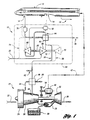
- FIGURE 1 is a schematic representation of a prior art ECS referred to as a minimum bleed configuration where the dotted lines represent conditions allowing adequate low temperature air to be supplied to the water separator;
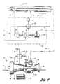
- FIGURE 2 is a schematic block diagram of another prior art ECS reffered to as an all-electric configuration;
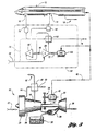
- FIGURE 3 is a schematic block diagram of another prior art ECS illustrating an all-electric configuration under maximum cooling demand;
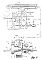
- FIGURE 4 is a schematic block diagram illustrating a prior art ECS configuration using an outflow turbine and bleed turbine to drive corresponding generators;
- FIGURE 5 illustrates an embodiment of the present invention using an outflow turbine, ram air compressor, and a second turbine and motor to drive the compressor in an all-electric configuration;
- FIGURE 6 illustrates an alternative minimum bleed configuration of the invention using switch dampers to alter the configuration based on cooling demand; and
- FIGURE 7 illustrates a minimum bleed configuration of the invention using switch dampers in a maximum economy mode.
- Referring now to Figure 1, an environmental control system (ECS), indicated generally by
reference numeral 10, is shown.ECS 10 provides fresh, pressurized or compressed air to a controlled space such ascabin 12. As used herein, cabin refers to the entire volume within the pressurized shell of an enclosed space such as the fuselage of an aircraft. In general,cabin 12 includes one or more inflow ports, indicated generally byreference numeral 14, for supplying fresh, pressurized air tocabin 12. The pressure withincabin 12 may be regulated by restricting theair exiting cabin 12 through an outflow port, indicated generally byreference numeral 16. Preferably, air passing throughoutflow port 16 is restricted by varying turbine parameters, as described in greater detail herein. However, an outflow valve may be used where required in combination with varying turbine inlet geometry. At a constant cabin pressure, the rate of air supplied throughinflow port 14 must be equal to the air exhausted fromcabin 12 throughoutflow port 16 in addition to air lost through leaks, indicated generally byreference numeral 18. The leaks represent both intentional and unintentional outward flow of air such as may occur through door seals, or pressure shell penetrations by tubes, wires, and the like. Throughout the drawings, double arrows are used to indicate air exhausted to atmosphere, or ambient. -
ECS 10 is powered by at least oneturbine engine 20. In one embodiment of the present invention, three such turbine engines are used to power an air-craft. Ram air, indicated generally byreference numeral 22, entersengine 20 throughfan 24 before passing throughmulti-stage compressor 26. The compressed air is fed to acombustion chamber 28 where it is mixed with fuel from afuel source 30. The combustion process is used to driveturbine 32 which is mechanically coupled byshaft 34 tocompressor 26. The jet exhaust then passes to atmosphere as indicated generally byreference numeral 36. - A transmission or
gear box 38 is mechanically coupled toshaft 34 to selectively drive agenerator 40 which generates electrical power, generally indicated byreference numeral 42, to meet the electrical demands of the vehicle. - Air may be extracted from
engine 20 fromfan 24 as indicated byreference numeral 44 or from ableed port 46.Reference numeral 46 represents both high stage, and low stage bleed air. Typically, low stage bleed air is extracted from the eighth stage ofmulti-stage compressor 26 whereas high stage bleed air is extracted from the fourteenth stage ofmulti-stage compressor 26. The embodiment illustrated in Figure 1 may be referred to as a minimum bleed configuration since the bleed air extracted is reduced from the prior art requirement of about 7.5 pounds (mass) per second (pps) to about 4 pps. - Bleed air (high stage or low stage) is extracted from
bleed port 46 and passes through a pre-cooler 48 where it is cooled byfan air 44. Preferably, pre-cooler 44 is a cross-flow, non-mixing, air-to-air heat exchanger which exhausts the cross-flow air to atmosphere as indicated byreference numeral 50. Due to the reduced flow requirements, pre-cooler 48 need reject only about 345 kw as opposed to the prior art design which requires heat rejection of about 640 kw. As such, less air is required fromfan 24 to achieve the required cooling. This may contribute to savings in percent SFC as described herein. - A portion of the
air exiting pre-cooler 48 is diverted as indicated byreference numeral 52 to provide anti-ice functions for the aircraft. The remaining air flow is directed into one ormore packs 54 for cooling prior to being supplied tocabin 12. Depending upon the particular application, an aircraft may have one pack associated with each engine, multiple engines associated with a single pack, or multiple packs associated with one or more engines. For purposes of describing the present invention,pack 54 represents one or more packs which satisfy the cooling and fresh air requirements forcabin 12.Air entering pack 54 may be routed through a first path, indicated generally byreference numeral 56, or a second path, indicated generally byreference numeral 58, depending upon the particular cooling demand and pressure differential betweencabin 12 and ambient. The path indicated bysolid lines 56 represents the path used to provide maximum cooling to an aircraft on a hot, humid day during a sea level climb. - As indicated in Figure 1,
path 56 routes bleed air from pre-cooler 48 toheat exchanger 60.Heat exchanger 60 includes a first inlet and corresponding first outlet in fluid communication withoutflow port 16 ofcabin 12.Heat exchanger 60 also includes a second inlet and corresponding second outlet in fluid communication withinflow port 14 ofcabin 12. As such, air exhausted fromcabin 12 passes through the first inlet and outlet ofheat exchanger 60 to cool air supplied tocabin 12 through the second inlet and outlet to increase the efficiency of the system. - As indicated in Figure 1,
heat exchanger 60 may be alternatively placed in fluid communication withinflow port 14 ofcabin 12 throughwater separator 62 either directly, as indicated by dashedline 64, or throughturbine 66 depending upon the cooling demand ofcabin 12. - A
compressor 68 receivesram air 22 through a compressor inlet to provide compressed air at the compressor outlet which is mixed with bleed air fromengine 20 before entering second inlet ofheat exchanger 60.Compressor 68 is mechanically coupled to and driven byturbine 66.Compressor 68 may also be driven by asecond turbine 70 which is mechanically coupled thereto viashaft 72 when operating in the high efficiency mode, such as during cruising at altitude.Second turbine 70 is driven by bleed air fromengine 20 as indicated generally byreference numeral 58. As such,turbine 70 is selectively mechanically coupled tocompressor 68 when functioning in the maximum efficiency or economy mode. The outlet ofturbine 70 is then in fluid communication with the outlet ofcompressor 68 where air is mixed prior to entering the second inlet ofheat exchanger 60. - To supply additional air flow through the first and second inlet and outlet of
heat exchanger 60, ram air may be provided during economy mode throughpath 74. For maximum cooling, alow pressure fan 76 may be used to extract available cooling effect fromair exiting cabin 12 throughoutflow port 16. In general, on a hot, humid day, theair exiting cabin 12 contains a significant amount of cooling effect which may be exploited viaheat exchanger 60.Low pressure fan 76 is used to provide a sufficient air flow when a reduced pressure ratio exists betweencabin 12 and atmosphere or ambient, such as typically occurs at or near sea level. Air exiting the first outlet ofheat exchanger 60 is exhausted to ambient as indicated generally byreference numeral 78. - The minimum bleed configuration illustrated in Figure 1 is based on providing the majority, if not all, of the cabin air from compression of ram air through
compressor 68. The duty of such a compressor is constant in mass flow rate and requires pressure rises far smaller than those produced at the bleed stage of the engines. This approach recovers as much energy as possible fromair exiting cabin 12 throughoutflow port 16. In the maximum economy mode, this air is passed throughturbine 66 whose power is used to partially supply the energy to drivecompressor 68 viashaft 80. As stated above, the outflow air has considerable available energy with respect to the outside ambient in most flight regimes other than at low altitudes. For example, considering a typical application at 35,000 feet altitude, aturbine 66 having an adiabatic efficiency of 80% would be able to recover 29.5 kw for each pps of air flow. For an inflow rate of about 6 pps at 35,000 feet, and a leak rate of about 1 pps, the energy available from the outflow air of about 5 pps can be recovered which amounts to around 150 kw. Use ofturbine 66 also provides another serendipitous effect: theair exiting turbine 66 is significantly cooler than ambient air such that it serves as an excellent heat sink for the heat exchange process ofpack 54. The additional power to drivecompressor 68 may be provided by the selectably engageableturbine 70 or alternatively by a motor, as illustrated and described herein. - For the configuration illustrated in Figure 1, representative calculations result in a required effectiveness for
heat exchanger 60 of about 0.74 as opposed to the required effectiveness of the prior art configuration which exceeds 0.90. As such,heat exchanger 60 can be smaller than the existing heat exchanger resulting in attendant savings in manufacturing costs and fuel cost during operation. - At low altitudes in hot conditions, the high efficiency configuration indicated by dashed lines in Figure 1 is modified to the maximum cooling configuration as indicated by the double solid lines of Figure 1. Under these conditions, the exhaust air from the cabin still provides a better heat sink than the ambient air so
low pressure fan 76 is included to move the exhaust air throughheat exchanger 60. To achieve the low temperatures needed to dehumidify and handle the cooling loads, ram air is compressed bycompressor 68 up to the bleed pressure and merged with bleed air prior to being cooled inheat exchanger 60.Turbine 66 is then used to expand and cool the supply air prior to enteringwater separator 62 and distribution ducts withincabin 12. - Computer simulations have been performed assuming isentropic efficiency of 80% for all turbo machines and 90% for the combined efficiency of
gear box 38 andgenerator 40. The parameters (heat rate, effectiveness, and log-mean temperature difference) forheat exchanger 60 operations were determined and operating conditions adjusted as required to match predetermined boundary conditions. In this embodiment, a model CF6-80 jet engine manufactured by General Electric was utilized. Other assumptions used for the simulation were that the fan bleed generated byfan 24 forpre-cooler 48 was reduced proportional to the reduction in the rate of bleedair exiting port 46 and that a constant electric load of 165 kw was provided for miscellaneous electrical loads. This configuration was analyzed for climb and descent flight regimes at sea level, 10K, 20K, 33K, and 40K feet and cruise at 43K feet. The computer simulations indicate a potential fuel savings of 3.31% SFC at cruise levels. - Referring now to Figures 2 and 3, another prior ant environmental control systems are shown. This embodiment may be referred to as an "all-electric" configuration since the use of bleed air from
engine 20 has been eliminated. Figure 2 illustrates the all-electric configuration having flows selectively arranged for maximum economy, while Figure 3 illustrates the flows to achieve maximum cooling. Likewise, Figure 2 is described using representative calculations for a 35,000 foot cruise, while Figure 3 uses representative calculations for a hot day sea level climb. Like reference numerals indicate similarity of function for components illustrated and described with reference to Figure 1. One of ordinary skill in the art will recognize that various flow rates, heat exchanger parameters, and other such considerations will vary depending upon the particular application. As such, the representative numbers found throughout the specification are provided to establish the viability of the various configurations under different operating conditions. The actual numbers may be ascertained for each particular application by one of ordinary skill in the art. For example, while pre-cooler 48 of Figures 2 and 3 appears schematically identical to pre-cooler 48 of Figure 1, the pre-cooler of Figures 2 and 3 must provide less heat rejection since the bleed air has been eliminated from the ECS function. As such, bleed air throughpre-cooler 48 of Figures 2 and 3 is provided only for the anti-ice function, indicated generally byreference numeral 52. - The all-electric configuration illustrated in Figures 2 and 3 may require a
larger gear box 38 andgenerator 40 than the corresponding components of Figure 1 to accommodate the increased electrical demand. For the maximum economy mode illustrated in Figure 2,generator 40 must provide 165 kw of electrical power tocabin 12 in addition to approximately 143 kw of electrical power formotor 100 which is mechanically coupled tocompressor 68 viashaft 72. Due to the approximate conversion efficiency of 90% used formotor 100, the 143 kw of electrical power is converted to about 129 kw of mechanical power transmitted tocompressor 68 viashaft 72. - In the configuration of Figure 2,
compressor 68 pressurizesram air 22 which passes throughheat exchanger 102 where it is cooled using air exhausted fromcabin 12 throughoutflow port 16.Turbine 66 is mechanically coupled tocompressor 68 viashaft 80.Turbine 66 includes an inlet in fluid communication withoutflow port 16 ofcabin 12 and an outlet in fluid communication with a first inlet and corresponding first outlet ofheat exchanger 102 to cool theair exiting compressor 68 and passing through a second inlet and corresponding second outlet ofheat exchanger 102.Turbine 66 expands and cools air exhausted fromcabin 12 to generate about 156 kw of mechanical power to drivecompressor 68 viashaft 80. If required,additional ram air 22 may be provided viapath 74 to the first inlet and outlet ofheat exchanger 102 to increase the heat rejection. For this configuration,heat exchanger 102 rejects about 293 kw of thermal energy but requires an effectiveness of about 0.93 to accommodate the maximum cooling regime illustrated in Figure 3. - To provide maximum cooling on a hot day at low altitude, the configuration of Figure 2 is modified via appropriate mechanization to achieve the configuration of Figure 3. Under these conditions,
generator 40 must provide about 235 kw of electrical power tomotor 100 in addition to the 165 kw of electrical power required for various equipment withincabin 12. As such,generator 40,motor 100, andgear box 38 should be sized accordingly. In this configuration,compressor 68 receivesram air 22 and delivers pressurized air to second inlet and corresponding second outlet ofheat exchanger 102, similar to the configuration of Figure 2. However, the second outlet ofheat exchanger 102 is in fluid communication with the inlet ofturbine 66 which expands and cools the air prior to enteringwater separator 62 and passing throughinflow port 14 ofcabin 12.Fan 76 is used to provide additional air flow through first inlet and outlet ofheat exchanger 102 since the pressure differential betweencabin 12 and atmosphere is insufficient to provide the necessary heat rejection, approximately 370 kw, byheat exchanger 102.Motor 100 provides about 211 kw of mechanical power to drivecompressor 68 viashaft 72.Compressor 68 is also driven viashaft 80 byturbine 66 which provides an additional 181 kw of mechanical power.Fan 76 requires about 2 kw of electrical power which is incorporated into the power demand of the cabin equipment. - As such, the environmental control system illustrated in Figures 2 and 3 includes
compressor 68 which receivesram air 22 through a compressor inlet to provide compressed air at the compressor outlet.Heat exchanger 102 includes a first inlet and corresponding first outlet for cooling air fromcompressor 68 which passes through a second inlet and corresponding second outlet. The first inlet ofheat exchanger 102 is in fluid communication withoutflow port 16 ofcabin 12 when the system is in the maximum cooling mode while being in communication with the outlet ofturbine 66 when the system is in the maximum economy mode.Turbine 66 is mechanically coupled tocompressor 68 and includes an inlet in fluid communication with the second outlet port ofheat exchanger 102 when the system is in the maximum cooling mode and in fluid communication withoutflow port 16 when the system is in the maximum economy mode.Turbine 66 also includes an outlet in communication withinflow port 14 ofcabin 12 when the system is in the maximum cooling mode, but in fluid communication with the second inlet ofheat exchanger 102 when the system is in the economy mode. As such,heat exchanger 102 recovers available energy from air exhausted throughoutflow port 16 to cool air supplied tocabin 12 throughinflow port 14. This configuration includesmotor 100 which is mechanically coupled tocompressor 68 for driving the compressor while functioning in both the maximum cooling mode and the economy mode. - Referring now to Figure 4, another prior art environmental control system according to the present invention is shown. The hexagons of Figure 4 are used to identify representative values for temperatures and pressures of air at various points throughout the system as summarized in Table 1 below.
TABLE 1. FULL BLEED FLOW CONFIGURATION 43,000 FEET CRUISE Symbol P (psia) T (°R) 1 29.3 856.9 2 13.7 725.4 3 3.38 402.1 4 2.35 649.1 A 2.35 416.3 C 10.92 535.0 D 11.45 520.0 P1 4.78 503.9 P2 4.67 929.8 V 10.85 520.0 - As indicated in Table 1, this configuration may be referred to as a "full bleed flow configuration". This arrangement provides electrical recovery of both outflow air and bleed air energy which is eventually converted back to mechanical energy provided to
engine 20 through amotor 110. In this configuration, afirst turbine 112 is interposedcabin 12 andheat exchanger 114 such that the inlet ofturbine 112 is in fluid communication withoutflow port 16 ofcabin 12, while the outlet ofturbine 112 is in fluid communication with the first inlet and corresponding first outlet ofheat exchanger 114.Turbine 112 expands and cools air exhausted fromcabin 12 to further cool air passing through second inlet and corresponding second outlet ofheat exchanger 114 prior to enteringinflow port 14 ofcabin 12.Turbine 112 is mechanically coupled to anelectric generator 116 viashaft 118 to convert about 145 kw of mechanical power to about 131 kw of electrical power, assuming an efficiency of about 90%. The electrical power is used to supply the power requirements forcabin 12 while excess power is fed tomotor 110 to help drivecompressor 26 viashaft 34 andgear box 38. Asecond turbine 120 receives bleed air frombleed port 46 ofengine 20.Turbine 120 is mechanically coupled togenerator 122 to convert mechanical energy from the turbine to electrical energy forcabin 12 and/ormotor 110. Assuming the representative numbers provided in Table 1,turbine 120 provides approximately 200 kw of mechanical power togenerator 122 viashaft 124 which is converted to about 180 kw of electrical power. Air exiting the outlet ofturbine 120 passes through the second inlet and corresponding second outlet ofheat exchanger 114 prior to enteringcabin 12 throughinflow port 14. Based on the representative numbers provided in Table 1, the effectiveness of theheat exchanger 114 should be about 0.76. - As with the embodiments illustrated in Figures 1-3,
heat exchanger 114 is preferably a cross-flow, non-mixing, air-to-air heat exchanger. While not specifically illustrated, this embodiment also includes a water separator placed betweenheat exchanger 114 andinflow port 14 ofcabin 12. - Based on the representative numbers of Table 1, the configuration of Figure 4 indicates a potential fuel savings of about 0.91% SFC for a typical application cruising at 43,000 feet altitude.
- Referring now to Figure 5, embodiment of an environmental control system according to the present invention is shown. The configuration of Figure 5 is an alternate all-electric configuration which does not use bleed air for the ECS function. While
pre-cooler 48 of Figure 4 appears schematically identical to pre-cooler 48 of Figures 1-4, the pre-cooler of Figure 5 provides less heat rejection since the bleed air has been eliminated from the ECS function. As such, bleed air throughpre-cooler 48 of Figure 5 is provided only for the anti-ice function, indicated generally byreference numeral 52.Generator 130 converts about 445 kw of mechanical power to about 400 kw of electrical power to supply 165 kw of electrical power tocabin 12 and about 235 kw of electrical power tomotor 132.Turbine 70 is mechanically coupled and driven bymotor 132 viashaft 134.Turbine 70 is also mechanically coupled tocompressor 68 viashaft 72. A firstdirectional valve 136 operates in conjunction with a seconddirectional valve 138 to selectively placeturbine 70 in fluid communication withheat exchanger 142. This provides additional cooling in a maximum cooling mode where energy recovery from the outflow air is insufficient to meet the cooling requirements forcabin 12. - As also illustrated in Figure 5, a mixing
valve 140 is provided to supply ram air viapath 144 toheat exchanger 142 where necessary. The ram air is combined with air exhausted from the outlet ofturbine 66 prior to passing throughheat exchanger 142. To improve efficiency of the ECS when cooling demand is lower,directional control valves turbine 70 from the flow path. As such,heat exchanger 142 is in fluid communication withinflow port 14 ofcabin 12 through a water separator (not specifically illustrated). As with Figure 4, representative numbers for the various states indicated by the hexagons of Figure 5 are summarized in Table 2 below.TABLE 2. ALL ELECTRIC CONFIGURATION SEA LEVEL CLIMB 43,000 FEET CRUISE Symbol P (psia) T (°R) P (psia) T (°R) 1 37.0 588 - - 2 17.1 495 -- -- 3 38.0 778.0 13.22 734.2 4 38.0 778.0 13.22 734.2 5 572.4 371.8 6 572.4 371.8 7 762.8 665.6 A 14.7 562.7 2.35 416.3 C 14.7 535 10.92 535 D 17.1 495 12.22 483.6 P 125.7 1119.1 34.82 999.5 P1 19.27 640.0 4.70 503.9 P2 17.14 754.2 4.67 929.8 R 16.22 578.8 3.66 472.7 V 14.63 570 - Referring now to Figures 6 and 7, another embodiment of an environmental control system according to the present invention is shown. Figure 6 illustrates the flow path for a maximum cooling mode of operation while Figure 7 illustrates the flow path for a maximum economy mode of operation. The flow path is altered using one or more switch dampers such as
first switch damper 150,second switch damper 152, and third switch damper 154. Representative numbers for pressures and temperatures throughout the system are indicated by the hexagons in the Figures and summarized below in Table 3 for various operating conditions.TABLE 3. MINIMUM BLEED AIR CONFIGURATION PRESSURES AND TEMPERATURES SEA LEVEL CLIMB 43,000 FEET CRUISE MAX ECONOMY 43,000 FEET CRUISE Symbol P (psia) T (°R) P (psia) T (°R) P (psia) T (°R) 1 56.6 642.7 29.26 856.9 34.82 999.5 2 17.3 495.0 13.22 717.7 13.22 806.2 3 57.6 894.4 13.22 734.2 13.22 734.2 4 57.6 842.6 728.2 13.22 13.22 757.5 5 14.9 572.4 2.55 372.8 2.55 371.8 6 14.9 572.4 2.55 371.8 2.55 371.8 7 772.8 666.1 657.5 A 14.7 562.6 2.35 416.3 2.35 416.3 B 57.60 798.4 29.26 856.9 34.82 999.5 C 14.78 535 10.92 535 10.92 535 D 17.10 41.07 12.22 483.6 12.24 520 P 125.7 1119.1 34.82 999.5 34.82 999.5 P1 19.27 640.0 4.78 503.9 4.78 503.9 P2 17.14 754.2 4.67 929.8 4.67 92.95 R 16.22 578.8 3.66 472.7 3.665 472.6 V 14.63 570 10.85 510 10.85 5.0 - As illustrated in Figures 6 and 7, switch
dampers turbine 70 either directly to the bleed air fromengine 20 or to the second outlet ofheat exchanger 160. At the same time, the switch dampers also selectively couple the outlet ofturbine 70 to eitherinflow port 14 ofcabin 12 or the second inlet port ofheat exchanger 160. Otherwise, the configuration illustrated in Figures 6 and 7 is similar to the minimum bleed configuration illustrated in Figure 1. The switch dampers function to reroute the flows such that, when needed, the bleed and compressed ram flows can be combined and then pre-cooled inheat exchanger 160. Further expansion throughturbine 70 brings the temperature down to the 35°F needed to support the water separation function performed by a water separator (not specifically illustrated). The switch dampers are needed only for the infrequent low-altitude and ground-cooling modes such that they are designed to be low loss devices when in the "straight-through" mode illustrated in Figure 7. -
Fan 76 is shown in parallel with acheck valve 162 to accommodate those cases where the cabin pressure is insufficient to support the exhaust of conditioned air fromcabin 12. Depending upon the particular application, the air driven byfan 76 may bypassturbine 66. - For all the embodiments illustrated and described which utilize a turbine in fluid communication with the
outflow port 16 ofcabin 12, every attempt should be made to make the turbine variable or controllable to provide a means of regulating the outflow rate at a particular pressure condition so as to regulate the rate of change of cabin pressure for a given inflow rate from the one or more packs. This may be accomplished by using adjustable or controllable inlet guide vanes or first-stage stator blades in the turbine. In an ideal case, such an arrangement makes an outflow valve unnecessary. However, an outflow valve may be provided in parallel to pass a small, variable amount of air to the ambient to accomplish cabin pressure control. Use of the outflow valve should be minimized, however, since any air exhausted through the outflow valve represents lost work.
Claims (11)
- An environmental control system (10) for a vehicle powered by at least one turbine engine (20), the vehicle including a cabin (12) having an inflow port (14) for receiving conditioned air and an outflow port (16) for exhausting air, the system comprising:a first turbine (66) having an inlet in fluid communication with the outflow port (16) of the cabin (12), the first turbine (66) expanding and cooling the air exhausted from the cabin (12), the air exiting the first turbine (66) through an outlet ;a heat exchanger (160) having a first inlet and corresponding first outlet in fluid communication with the outlet of the first turbine (66) for cooling air passing through a second inlet and corresponding second outlet prior to entering the inflow port (14) of the cabin (12);a compressor (68) mechanically coupled to and driven by the first turbine (66), the compressor (68) receiving ram air (22) through a compressor inlet to provide compressed air at a compressor outlet, the compressor outlet being in fluid communication with the second inlet of the heat exchanger (160);a second turbine (70) mechanically coupled to the compressor for providing energy to drive the compressor, the second turbine (70) having an inlet receiving bleed air from the engine (20) and an outlet providing conditioned air to the cabin (12); andat least one switch damper (150, 152, 154) for selectively coupling the inlet of the second turbine (70) either directly to the bleed air from the engine (20) or to the second outlet of the heat exchanger (160) and for selectively coupling the outlet of the second turbine (70) to either the inflow port (14) of the cabin (12) or the second inlet port of the heat exchanger (160).
- The system of claim 1 further comprising:a fan (76) interposed the outflow port (16) of the cabin (12) and the inlet of the first turbine (66) for selectively moving air through the first turbine (66) and the heat exchanger (160) when a reduced pressure ratio across the turbine (66) provides insufficient air movement.
- The system of claim 1 or 2 further comprising a motor (132) coupled to the second turbine (70) and the compressor (68) to provide additional energy to drive the compressor (68).
- The system of claims any of the precceding claims wherein said at least one switch damper comprises:a first switch damper (150) interposed the engine (20) and the second turbine (70) having a first selectable state for coupling bleed air from the engine to the inlet of the second turbine and a second selectable state for coupling bleed air from the engine to the outlet of the compressor and the second outlet of the heat exchanger to the inlet of the second turbine;a second switch damper (152) interposed the first switch damper (150) and the compressor (68) having a first selectable state for coupling the outlet of the second turbine to the outlet of the compressor and a second selectable state for coupling the bleed air from the engine to the outlet of the compressor and the outlet of the second turbine to the inflow port of the cabin; anda third switch damper (154) interposed the heat exchanger (160) and the cabin (12) having a first selectable state for coupling the second outlet of the heat exchanger to the inflow port of the cabin and a second state for coupling the outlet of the second turbine to the inflow port of the cabin and the second outlet of the heat exchanger to the inlet of the second turbine.
- The system of claim 1 further comprising:a switch damper interposed the first turbine (66) and the heat exchanger (160) having a first selectable position for coupling the outlet of the first turbine to the first inlet of the heat exchanger and a second selectable position for coupling ram air to the first inlet of the heat exchanger.
- An environmental control system (10) as set forth in claim 1, wherein said vehicle is an aircraft, wherein said second turbine (120) is selectively coupled to the compressor having an inlet selectively coupled to the second outlet of the heat exchanger and an outlet selectively coupled to the inflow port of the cabin;
said system further comprising: a motor (110) selectively coupled to the second turbine and coupled to the compressor for providing driving energy to the compressor;
a first directional valve (136) interposed the heat exchanger and the inflow port of the cabin for selectably coupling the second outlet of the heat exchanger to either the inlet of the second turbine or the inflow port of the cabin; and
a second directional valve (138) interposed the first directional valve and the inflow port of the cabin for selectably coupling either the outlet of the second turbine or the second outlet of the heat exchanger co the inflow port of the cabin. - The system of claim 6 further comprising:a fan (76) interposed the outflow port of the cabin and the inlet of the first turbine for selectively moving air through the first turbine and the heat exchanger when a reduced pressure ratio across the turbine provides insufficient air movement.
- The system of claim 6 or 7 further comprising:a mixing valve (140) interposed the outlet of the first turbine and the first inlet of the heat exchanger for selectively mixing ram air with air exiting the outlet of the first turbine.
- An environmental control system (10) as set forth in claim 1, wherein said vehicle is an aircraft, the system having a maximum cooling mode and an economy mode,
said heat exchanger (102) having a first inlet and corresponding first outlet for cooling air passing through a second inlet and corresponding second outlet, the first inlet being in fluid communication with the outflow port of the cabin when in the maximum cooling mode; and
said first turbine (66) being mechanically coupled to the compressor, the first turbine having an inlet in fluid communication with the second outlet port of the heat exchanger when in the maximum cooling mode and in fluid communication with the outflow port when in the economy mode, the first turbine also having an outlet in communication with the inflow port of the cabin when in the maximum cooling mode, the outlet being in fluid communication with the second inlet of the heat exchanger when in the economy mode, wherein the heat exchanger recovers energy from air exhausted from the cabin to cool air supplied to the cabin. - The system of claim 9 wherein said second turbine (120) is selectively mechanically coupled to the compressor when functioning in the economy mode, the second turbine having an inlet receiving bleed air from the engine and an outlet in fluid communication with the outlet of the compressor when functioning in the economy mode.
- The system of claim 9 or 10 further comprising a motor (110) mechanically coupled to the compressor for driving the compressor while functioning in both the maximum cooling mode and the economy mode.
Applications Claiming Priority (2)
| Application Number | Priority Date | Filing Date | Title |
|---|---|---|---|
| US08/887,018 US5967461A (en) | 1997-07-02 | 1997-07-02 | High efficiency environmental control systems and methods |
| US887018 | 1997-07-02 |
Publications (4)
| Publication Number | Publication Date |
|---|---|
| EP0888966A2 EP0888966A2 (en) | 1999-01-07 |
| EP0888966A3 EP0888966A3 (en) | 2001-01-31 |
| EP0888966B1 true EP0888966B1 (en) | 2006-06-28 |
| EP0888966B2 EP0888966B2 (en) | 2011-01-19 |
Family
ID=25390283
Family Applications (1)
| Application Number | Title | Priority Date | Filing Date |
|---|---|---|---|
| EP98111967A Expired - Lifetime EP0888966B2 (en) | 1997-07-02 | 1998-06-29 | High efficiency environmental control system |
Country Status (3)
| Country | Link |
|---|---|
| US (1) | US5967461A (en) |
| EP (1) | EP0888966B2 (en) |
| DE (1) | DE69835054T3 (en) |
Cited By (1)
| Publication number | Priority date | Publication date | Assignee | Title |
|---|---|---|---|---|
| CN101239659B (en) * | 2002-10-22 | 2012-10-10 | 波音公司 | Airplane, method and system for providing air from air conditioner to the airplane |
Families Citing this family (147)
| Publication number | Priority date | Publication date | Assignee | Title |
|---|---|---|---|---|
| US6124646A (en) * | 1998-02-11 | 2000-09-26 | Alliedsignal Inc. | Aircraft air conditioning system including electric generator for providing AC power having limited frequency range |
| GB9804784D0 (en) * | 1998-03-06 | 1998-04-29 | Rolls Royce Plc | Environmental control system |
| US6545610B2 (en) * | 1999-05-25 | 2003-04-08 | Kulite Semiconductor Products, Inc. | Pressure transducer and switch combination |
| WO2000074831A1 (en) * | 1999-06-09 | 2000-12-14 | Aeroflo (Proprietary) Limited | Method and device for mixing gases |
| US6247668B1 (en) * | 1999-07-15 | 2001-06-19 | The Boeing Company | Auxiliary power and thrust unit |
| US6199387B1 (en) | 1999-07-30 | 2001-03-13 | Liebherr-Aerospace Lindenberg Gmbh | Air-conditioning system for airplane cabin |
| DE19935918B4 (en) * | 1999-07-30 | 2006-08-31 | Liebherr-Aerospace Lindenberg Gmbh | Air conditioning system for aircraft cabins |
| US6305156B1 (en) * | 1999-09-03 | 2001-10-23 | Alliedsignal Inc. | Integrated bleed air and engine starting system |
| FR2800706B1 (en) * | 1999-11-10 | 2002-01-18 | Dassault Aviat | METHOD AND DEVICE FOR SUPPLYING A FRESH AIR INTAKE FROM THE CABIN OF AN AIRCRAFT POWERED BY AT LEAST ONE JET ENGINE |
| DE19963280C1 (en) * | 1999-12-27 | 2001-08-23 | Liebherr Aerospace Gmbh | Air conditioning system for aircraft cabins |
| US6427471B1 (en) * | 2000-02-29 | 2002-08-06 | Shimadzu Corporation | Air cycle machine and air conditioning system using the same |
| US6415595B1 (en) | 2000-08-22 | 2002-07-09 | Hamilton Sundstrand Corporation | Integrated thermal management and coolant system for an aircraft |
| US6681592B1 (en) * | 2001-02-16 | 2004-01-27 | Hamilton Sundstrand Corporation | Electrically driven aircraft cabin ventilation and environmental control system |
| FR2823181B1 (en) * | 2001-04-06 | 2003-08-22 | Dassault Aviat | FRESH AIR SUPPLY DEVICE FOR AN AIRCRAFT |
| US6526775B1 (en) * | 2001-09-14 | 2003-03-04 | The Boeing Company | Electric air conditioning system for an aircraft |
| US6817575B1 (en) * | 2001-09-20 | 2004-11-16 | Hamilton Sundstrand Corporation | Integrated system for providing aircraft environmental control |
| US6796527B1 (en) * | 2001-09-20 | 2004-09-28 | Hamilton Sundstrand Corporation | Integrated air turbine driven system for providing aircraft environmental control |
| GB0122672D0 (en) * | 2001-09-20 | 2001-11-14 | Honeywell Normalair Garrett | Environmental control systems |
| US6783114B2 (en) | 2001-12-11 | 2004-08-31 | Honeywell International, Inc. | Cable assembly and air outflow valve incorporating the same |
| WO2003086859A1 (en) * | 2002-04-08 | 2003-10-23 | Honeywell Normalair-Garrett (Holdings) Limited | Air conditioning system |
| US20040025507A1 (en) * | 2002-08-02 | 2004-02-12 | Honeywell International Inc. | Turbo compressor for use in OBIGGS application |
| US6684660B1 (en) * | 2002-08-08 | 2004-02-03 | Hamilton Sundstrand | Pneumatic cabin super charger |
| LU90967B1 (en) * | 2002-09-16 | 2004-03-17 | Ipalco Bv | Device for supplying preconditioned air to an aircraft on the ground |
| GB2396208A (en) * | 2002-12-14 | 2004-06-16 | Rolls Royce Plc | Environmental control system |
| US6834831B2 (en) * | 2002-12-31 | 2004-12-28 | The Boeing Company | Hybrid solid oxide fuel cell aircraft auxiliary power unit |
| US6848261B2 (en) * | 2003-04-03 | 2005-02-01 | Honeywell International Inc. | Condensing cycle with energy recovery augmentation |
| DE10350541A1 (en) * | 2003-10-29 | 2005-06-16 | Liebherr-Aerospace Lindenberg Gmbh | Air conditioning system and method for treating air for air conditioning of a room |
| DE102004017879B4 (en) * | 2004-04-13 | 2006-11-09 | Liebherr-Aerospace Lindenberg Gmbh | Air treatment system |
| DE102004024057B3 (en) * | 2004-05-13 | 2005-09-15 | Airbus Deutschland Gmbh | Aircraft, has fluid duct system connected to pumping device that is driven, by cabin exhaust air, for production of low pressure for suction of boundary layer though valve, where device is jet pump whose driving jets are generated by air |
| US7246482B2 (en) * | 2004-07-16 | 2007-07-24 | Honeywell International, Inc. | Gas turbine engine bleed air power assist system and method |
| US7322202B2 (en) * | 2004-09-22 | 2008-01-29 | Hamilton Sundstrand Corporation | Electric motor driven supercharger with air cycle air conditioning system |
| US7334423B2 (en) * | 2004-09-22 | 2008-02-26 | Hamilton Sundstrand Corporation | Dual mode condensing cycle |
| DE102004061372B4 (en) * | 2004-12-21 | 2011-05-26 | Airbus Operations Gmbh | Arrangement and method for using waste heat for heating the bilge area of aircraft |
| US7513119B2 (en) * | 2005-02-03 | 2009-04-07 | The Boeing Company | Systems and methods for starting aircraft engines |
| US7380749B2 (en) * | 2005-04-21 | 2008-06-03 | The Boeing Company | Combined fuel cell aircraft auxiliary power unit and environmental control system |
| FR2889250B1 (en) | 2005-07-28 | 2007-09-07 | Airbus France Sas | PROPELLER ASSEMBLY FOR AIRCRAFT AND AIRCRAFT COMPRISING AT LEAST ONE SUCH PROPELLER ASSEMBLY |
| US7481214B2 (en) * | 2005-09-19 | 2009-01-27 | The Boeing Company | System and method for enriching aircraft cabin air with oxygen from a nitrogen generation system |
| US7721554B2 (en) * | 2006-02-02 | 2010-05-25 | General Electric Company | Aircraft auxiliary gas turbine engine and method for operating |
| DE102006005037B4 (en) * | 2006-02-03 | 2012-03-29 | Airbus Operations Gmbh | Air conditioning arrangement for an aircraft with several individually temperature-controllable climates |
| WO2007098322A2 (en) * | 2006-02-10 | 2007-08-30 | Aronstam Peter S | Apparatus and methods of using card based programmable controllers |
| US7673459B2 (en) * | 2006-04-05 | 2010-03-09 | General Electric Company | System and method for providing air to a compressor of an aircraft auxiliary gas turbine engine |
| US7595570B2 (en) * | 2006-08-30 | 2009-09-29 | Kulite Semiconductor Products, Inc. | Solid state pressure switch |
| DE102006048622A1 (en) * | 2006-10-13 | 2008-04-24 | Airbus Deutschland Gmbh | Outlet pipeline connection deicing arrangement for aircraft, has two pipe lines connected to either of other two pipelines for transporting and fed valve regulating temperature-reduced fresh air to latter pipelines |
| US7707838B2 (en) * | 2006-10-31 | 2010-05-04 | General Electric Company | Auxiliary power unit assembly |
| US7778735B2 (en) * | 2006-11-17 | 2010-08-17 | The Boeing Company | Environmental control system, method, and computer program product for controlling the interior environment of a pressurized compartment |
| US7690595B2 (en) * | 2006-12-12 | 2010-04-06 | Lockheed Martin Corporation | System, method, and apparatus for throat corner scoop offtake for mixed compression inlets on aircraft engines |
| FR2911580B1 (en) * | 2007-01-22 | 2009-02-27 | Airbus France Sas | AIR CONDITIONING SYSTEM FOR AIRCRAFT |
| US7871038B2 (en) * | 2007-05-17 | 2011-01-18 | The Boeing Company | Systems and methods for providing airflow in an aerospace vehicle |
| US7849702B2 (en) * | 2007-06-20 | 2010-12-14 | The Boeing Company | Combined cabin air and heat exchanger RAM air inlets for aircraft environmental control systems, and associated methods of use |
| ES2349206B1 (en) * | 2007-10-01 | 2011-10-24 | Airbus Operations, S.L. | DEVICE FOR CONTROL OF THE DEMAND FOR VENTILATION AND AIR CONDITIONING OF AN AIRCRAFT ON EARTH. |
| US7687927B2 (en) * | 2007-11-21 | 2010-03-30 | The Boeing Company | Electrical systems architecture for an aircraft, and related operating methods |
| DE102008019146A1 (en) * | 2008-04-16 | 2009-11-05 | Airbus Deutschland Gmbh | Deicing system for an aircraft |
| DE102008048915B4 (en) * | 2008-09-26 | 2017-05-18 | Airbus Operations Gmbh | Power distribution system |
| US20100107594A1 (en) * | 2008-10-31 | 2010-05-06 | General Electric Company | Turbine integrated bleed system and method for a gas turbine engine |
| US20100172757A1 (en) * | 2009-01-07 | 2010-07-08 | Henderson Dale A | Indirect drive unit apparatus, system and method |
| US8657227B1 (en) | 2009-09-11 | 2014-02-25 | The Boeing Company | Independent power generation in aircraft |
| GB201020783D0 (en) * | 2010-12-08 | 2011-01-19 | Eaton Aerospace Ltd | On board inert gas generation system |
| DE102011011879A1 (en) * | 2011-02-21 | 2012-08-23 | Airbus Operations Gmbh | Cooling air inlet, engine bleed air system and method for operating a cooling air inlet |
| US8738268B2 (en) | 2011-03-10 | 2014-05-27 | The Boeing Company | Vehicle electrical power management and distribution |
| US9169024B2 (en) * | 2011-05-09 | 2015-10-27 | Honeywell International Inc. | Environmental control system with closed loop pressure cycle |
| US20130040545A1 (en) * | 2011-08-11 | 2013-02-14 | Hamilton Sundstrand Corporation | Low pressure compressor bleed exit for an aircraft pressurization system |
| US9555893B2 (en) * | 2011-11-28 | 2017-01-31 | Hamilton Sundstrand Corporation | Blended flow air cycle system for environmental control |
| GB2499576A (en) * | 2011-11-29 | 2013-08-28 | Eaton Aerospace Ltd | Aircraft on board inert gas generation system |
| US9109514B2 (en) * | 2012-01-10 | 2015-08-18 | Hamilton Sundstrand Corporation | Air recovery system for precooler heat-exchanger |
| US8955794B2 (en) * | 2012-01-24 | 2015-02-17 | The Boeing Company | Bleed air systems for use with aircrafts and related methods |
| US8967528B2 (en) * | 2012-01-24 | 2015-03-03 | The Boeing Company | Bleed air systems for use with aircrafts and related methods |
| WO2014020770A1 (en) * | 2012-08-03 | 2014-02-06 | 株式会社島津製作所 | Turbine compressor device, turbine compressor system, and aircraft ventilation system |
| US9669936B1 (en) * | 2012-10-24 | 2017-06-06 | The Boeing Company | Aircraft air conditioning systems and methods |
| US20140144163A1 (en) * | 2012-11-23 | 2014-05-29 | Airbus Operations Gmbh | Aircraft air conditioning system and method of operating an aircraft air conditioning system |
| US10563592B2 (en) * | 2012-12-14 | 2020-02-18 | United Technologies Corporation | Turbo compressor for bleed air |
| US10184494B2 (en) | 2013-06-28 | 2019-01-22 | Hamilton Sundstrand Corporation | Enhance motor cooling system and method |
| EP3036118B1 (en) * | 2013-08-21 | 2024-01-10 | RTX Corporation | Environmental control generator system and apparatus |
| WO2015026432A1 (en) * | 2013-08-21 | 2015-02-26 | Hamilton Sundstrand Corporation | Single stage engine bleed |
| US10745136B2 (en) | 2013-08-29 | 2020-08-18 | Hamilton Sunstrand Corporation | Environmental control system including a compressing device |
| US9580180B2 (en) | 2014-03-07 | 2017-02-28 | Honeywell International Inc. | Low-pressure bleed air aircraft environmental control system |
| US9656756B2 (en) * | 2014-03-10 | 2017-05-23 | The Boeing Company | Turbo-compressor system and method for extracting energy from an aircraft engine |
| US10054051B2 (en) * | 2014-04-01 | 2018-08-21 | The Boeing Company | Bleed air systems for use with aircraft and related methods |
| US9810158B2 (en) | 2014-04-01 | 2017-11-07 | The Boeing Company | Bleed air systems for use with aircraft and related methods |
| US9878794B2 (en) * | 2014-04-24 | 2018-01-30 | Hamilton Sundstrand Corporation | Environmental control system utilizing shoestring cycle to maximize efficiency |
| US9869190B2 (en) | 2014-05-30 | 2018-01-16 | General Electric Company | Variable-pitch rotor with remote counterweights |
| BR102015015377B1 (en) * | 2014-06-27 | 2022-04-26 | United Technologies Corporation | Gas turbine engine assembly and aircraft environmental control system |
| EP2998223B1 (en) * | 2014-09-19 | 2018-12-05 | Airbus Operations GmbH | Aircraft air conditioning system and method of operating an aircraft air conditioning system |
| US10072510B2 (en) | 2014-11-21 | 2018-09-11 | General Electric Company | Variable pitch fan for gas turbine engine and method of assembling the same |
| US11466904B2 (en) * | 2014-11-25 | 2022-10-11 | Hamilton Sundstrand Corporation | Environmental control system utilizing cabin air to drive a power turbine of an air cycle machine and utilizing multiple mix points for recirculation air in accordance with pressure mode |
| US10549860B2 (en) * | 2014-11-25 | 2020-02-04 | Hamilton Sundstrand Corporation | Environmental control system utilizing cabin air to drive a power turbine of an air cycle machine |
| US9994323B2 (en) * | 2015-03-04 | 2018-06-12 | Hamilton Sundstrand Corporation | Replacement system providing replacement air to an inerting system |
| JP6343243B2 (en) * | 2015-03-09 | 2018-06-13 | 川崎重工業株式会社 | Aircraft power generator |
| US9840333B2 (en) * | 2015-04-24 | 2017-12-12 | Hamilton Sundstrand Corporation | Environmental control system mixing cabin discharge air with bleed air during a cycle |
| US10494106B2 (en) * | 2015-05-11 | 2019-12-03 | United Technologies Corporation | Environmental cooling systems for aircraft |
| US10160547B2 (en) * | 2015-05-26 | 2018-12-25 | Hamilton Sundstrand Corporation | Aircraft environmental control system |
| CA2988959C (en) * | 2015-06-08 | 2023-10-03 | Hamilton Sundstrand Corporation | Cabin discharge air assist without a primary heat exchanger |
| US10814988B2 (en) * | 2015-06-08 | 2020-10-27 | Hamilton Sunstrand Corporation | Unequal bleed flow |
| US10100744B2 (en) | 2015-06-19 | 2018-10-16 | The Boeing Company | Aircraft bleed air and engine starter systems and related methods |
| US9771165B2 (en) * | 2015-06-25 | 2017-09-26 | Pratt & Whitney Canada Corp. | Compound engine assembly with direct drive of generator |
| US10710738B2 (en) | 2015-06-25 | 2020-07-14 | Pratt & Whitney Canada Corp. | Auxiliary power unit with intercooler |
| US10696417B2 (en) | 2015-06-25 | 2020-06-30 | Pratt & Whitney Canada Corp. | Auxiliary power unit with excess air recovery |
| US10590842B2 (en) | 2015-06-25 | 2020-03-17 | Pratt & Whitney Canada Corp. | Compound engine assembly with bleed air |
| GB201513952D0 (en) | 2015-08-07 | 2015-09-23 | Rolls Royce Plc | Aircraft pneumatic system |
| US9784638B1 (en) * | 2015-08-31 | 2017-10-10 | The Boeing Company | Method and system for diagnoses and prognoses of low temperature limit control valve |
| DE102015217804A1 (en) * | 2015-09-17 | 2017-03-23 | Airbus Operations Gmbh | Ram air duct arrangement and method for operating a ram air duct arrangement |
| US10100653B2 (en) | 2015-10-08 | 2018-10-16 | General Electric Company | Variable pitch fan blade retention system |
| DE102015222193A1 (en) * | 2015-11-11 | 2017-05-11 | Airbus Operations Gmbh | Aircraft air conditioner with a cabin exhaust air turbine |
| US20170313435A1 (en) * | 2016-04-29 | 2017-11-02 | Hamilton Sundstrand Corporation | Fuel tank inerting systems for aircraft |
| CN105966624B (en) * | 2016-05-23 | 2018-06-22 | 北京航空航天大学 | A kind of cockpit air return system of aircraft cockpit air-discharging and supercharging acting driving |
| US10773807B2 (en) | 2016-05-26 | 2020-09-15 | Hamilton Sunstrand Corporation | Energy flow of an advanced environmental control system |
| US10604263B2 (en) | 2016-05-26 | 2020-03-31 | Hamilton Sundstrand Corporation | Mixing bleed and ram air using a dual use turbine system |
| US10870490B2 (en) * | 2016-05-26 | 2020-12-22 | Hamilton Sunstrand Corporation | Energy flow |
| US11511867B2 (en) * | 2016-05-26 | 2022-11-29 | Hamilton Sundstrand Corporation | Mixing ram and bleed air in a dual entry turbine system |
| US11506121B2 (en) * | 2016-05-26 | 2022-11-22 | Hamilton Sundstrand Corporation | Multiple nozzle configurations for a turbine of an environmental control system |
| US10232948B2 (en) | 2016-05-26 | 2019-03-19 | Hamilton Sundstrand Corporation | Mixing bleed and ram air at a turbine inlet of a compressing device |
| US11047237B2 (en) | 2016-05-26 | 2021-06-29 | Hamilton Sunstrand Corporation | Mixing ram and bleed air in a dual entry turbine system |
| EP3254970B1 (en) | 2016-05-26 | 2020-04-29 | Hamilton Sundstrand Corporation | An environmental control system with an outflow heat exchanger |
| EP3248877B1 (en) | 2016-05-26 | 2023-05-10 | Hamilton Sundstrand Corporation | Mixing bleed and ram air at a turbine inlet |
| US10144517B2 (en) | 2016-05-26 | 2018-12-04 | Hamilton Sundstrand Corporation | Mixing bleed and ram air using a two turbine architecture with an outflow heat exchanger |
| US10137993B2 (en) | 2016-05-26 | 2018-11-27 | Hamilton Sundstrand Corporation | Mixing bleed and ram air using an air cycle machine with two turbines |
| US10451353B2 (en) | 2016-08-05 | 2019-10-22 | Hamilton Sundstrand Corporation | Aircraft electronics thermal regulation systems |
| US11203949B2 (en) * | 2016-08-11 | 2021-12-21 | General Electric Company | Mechanically driven air vehicle thermal management device |
| US11377216B2 (en) * | 2016-08-23 | 2022-07-05 | Ge Aviation Systems Llc | Advanced method and aircraft for pre-cooling an environmental control system using a dual compressor four wheel turbo-machine |
| US10358221B2 (en) * | 2016-08-23 | 2019-07-23 | Ge Aviation Systems Llc | Hybrid method and aircraft for pre-cooling an environmental control system using a power generator four wheel turbo-machine |
| EP3296208B1 (en) * | 2016-09-14 | 2019-07-03 | Airbus Operations, S.L. | Aircraft incorporating a cabin air recovery system |
| US10669940B2 (en) * | 2016-09-19 | 2020-06-02 | Raytheon Technologies Corporation | Gas turbine engine with intercooled cooling air and turbine drive |
| US10569885B2 (en) * | 2017-01-20 | 2020-02-25 | Honeywell Uk Limited | Environmental control system for an aeronautic vehicle |
| US10086946B1 (en) | 2017-04-03 | 2018-10-02 | Hamilton Sundstrand Corporation | Hybrid third air condition pack |
| US10526092B2 (en) * | 2017-04-03 | 2020-01-07 | Hamilton Sundstrand Corporation | Turbine-assisted cabin air compressor |
| US10507928B2 (en) | 2017-06-16 | 2019-12-17 | Honeywell International Inc. | High efficiency electrically driven environmental control system |
| US10843804B2 (en) * | 2017-08-01 | 2020-11-24 | Honeywell International Inc. | Cabin outflow air energy optimized cabin pressurizing system |
| FR3072077B1 (en) * | 2017-10-05 | 2019-09-20 | Liebherr-Aerospace Toulouse | AUTONOMOUS RECOVERY MODULE OF A CABIN OF AN AIRCRAFT AND METHOD THEREOF |
| US11254435B2 (en) * | 2017-10-13 | 2022-02-22 | Hamilton Sundstrand Corporation | Supplemental pack driven by bleed air and cabin air |
| US10914242B2 (en) * | 2017-11-28 | 2021-02-09 | Raytheon Technologies Corporation | Complex air supply system for gas turbine engine and associated aircraft |
| US11396378B2 (en) * | 2018-01-24 | 2022-07-26 | Hamilton Sundstrand Corporation | ECS dual entry ram inlet plenum |
| US10988262B2 (en) | 2018-03-14 | 2021-04-27 | Honeywell International Inc. | Cabin pressure control system architecture using cabin pressure air for inlet to APU core compressor |
| US10738703B2 (en) * | 2018-03-22 | 2020-08-11 | Raytheon Technologies Corporation | Intercooled cooling air with combined features |
| US11273917B2 (en) | 2018-05-29 | 2022-03-15 | Honeywell International Inc. | Cabin discharge air management system and method for auxiliary power unit |
| US10954865B2 (en) | 2018-06-19 | 2021-03-23 | The Boeing Company | Pressurized air systems for aircraft and related methods |
| US10774874B2 (en) * | 2018-08-06 | 2020-09-15 | General Electric Company | Fluid bearing assembly |
| DE102018126921A1 (en) * | 2018-10-29 | 2020-04-30 | Airbus Operations Gmbh | Aircraft refrigeration system with a motor-assisted cabin exhaust turbine |
| WO2020095477A1 (en) * | 2018-11-06 | 2020-05-14 | 株式会社Ihi | Aircraft air conditioning device |
| US11465757B2 (en) * | 2018-12-06 | 2022-10-11 | The Boeing Company | Systems and methods to produce aircraft cabin supply air |
| EP3744637A1 (en) | 2019-05-31 | 2020-12-02 | Hamilton Sundstrand Corporation | Aircraft environmental control system |
| US11332252B2 (en) | 2019-06-11 | 2022-05-17 | Hamilton Sundstrand Corporation | Using bleed air to supply outside air to a cabin |
| US11377217B2 (en) | 2019-06-11 | 2022-07-05 | Hamilton Sundstrand Corporation | Using bleed air to supply outside air to a cabin |
| US11629870B2 (en) | 2020-03-17 | 2023-04-18 | Hamilton Sundstrand Corporation | ECS using cabin outflow air as an electricity source |
| DE102020006235A1 (en) | 2020-10-09 | 2022-04-14 | Airbus Defence and Space GmbH | Air guiding arrangement for an aircraft with an integrated heat exchanger |
| US11486315B2 (en) | 2020-11-06 | 2022-11-01 | Ge Aviation Systems Llc | Combustion engine including turbomachine |
| US20220169393A1 (en) * | 2020-11-30 | 2022-06-02 | Hamilton Sundstrand Corporation | Ambient air architecture with single air cycle machine and high pressure water separator |
| US11674435B2 (en) | 2021-06-29 | 2023-06-13 | General Electric Company | Levered counterweight feathering system |
| US11795964B2 (en) | 2021-07-16 | 2023-10-24 | General Electric Company | Levered counterweight feathering system |
Family Cites Families (24)
| Publication number | Priority date | Publication date | Assignee | Title |
|---|---|---|---|---|
| US2391838A (en) * | 1945-12-25 | Air conditioning system | ||
| US2734443A (en) * | 1956-02-14 | Enclosure air supply system | ||
| US2453923A (en) * | 1946-08-20 | 1948-11-16 | Douglas Aircraft Co Inc | Aircraft cooling by air turbine means |
| US2777301A (en) * | 1952-06-30 | 1957-01-15 | Garrett Corp | All-purpose power and air conditioning system |
| US2870698A (en) * | 1957-04-30 | 1959-01-27 | United Aircraft Corp | Recirculating flow aircraft air conditioning system |
| US3326109A (en) * | 1964-03-11 | 1967-06-20 | Bristol Siddeley Engines Ltd | Air conditioning systems for aircraft |
| GB1104887A (en) * | 1965-01-22 | 1968-03-06 | Westward Aircraft Ltd | Improvements in or relating to cooling systems for aircraft cabins and other enclosures |
| US4261416A (en) * | 1979-02-23 | 1981-04-14 | The Boeing Company | Multimode cabin air conditioning system |
| US4312191A (en) * | 1980-02-15 | 1982-01-26 | Sundstrand Corporation | Environmental control system for aircraft with improved efficiency |
| GB2076897B (en) * | 1980-06-02 | 1983-06-29 | Rockwell International Corp | Integrated auxiliary and environmental control unit |
| US4419926A (en) * | 1980-09-02 | 1983-12-13 | Lockheed Corporation | ESC energy recovery system for fuel-efficient aircraft |
| US4546939A (en) * | 1982-05-27 | 1985-10-15 | Lockheed Corporation | Energy efficient ECS powered by a variable voltage/variable frequency power system |
| US4445342A (en) * | 1982-08-26 | 1984-05-01 | United Technologies Corporation | Multi-zone temperature control in air cycle refrigeration systems |
| FR2609686B1 (en) * | 1987-01-16 | 1992-03-13 | Abg Semca | HIGH-PERFORMANCE AIR CONDITIONING SYSTEM FOR AERONAUTICAL MACHINERY |
| US5143329A (en) * | 1990-06-01 | 1992-09-01 | General Electric Company | Gas turbine engine powered aircraft environmental control system and boundary layer bleed |
| US5125597A (en) * | 1990-06-01 | 1992-06-30 | General Electric Company | Gas turbine engine powered aircraft environmental control system and boundary layer bleed with energy recovery system |
| US5145124A (en) * | 1990-07-12 | 1992-09-08 | Allied-Signal Inc. | Fluid conditioning system and apparatus |
| US5299763A (en) * | 1991-12-23 | 1994-04-05 | Allied-Signal Inc. | Aircraft cabin air conditioning system with improved fresh air supply |
| DE4320302C2 (en) * | 1993-06-18 | 1996-09-12 | Daimler Benz Aerospace Airbus | Arrangement for energy generation on board an aircraft, in particular a passenger aircraft |
| US5490645A (en) * | 1993-12-09 | 1996-02-13 | Allied-Signal Inc. | Fully integrated environmental and secondary power system |
| US5442905A (en) * | 1994-04-08 | 1995-08-22 | Alliedsignal Inc. | Integrated power and cooling environmental control system |
| US5461882A (en) † | 1994-07-22 | 1995-10-31 | United Technologies Corporation | Regenerative condensing cycle |
| GB9508043D0 (en) † | 1995-04-20 | 1995-06-07 | British Aerospace | Environmental control system |
| US5813630A (en) * | 1996-09-27 | 1998-09-29 | Mcdonnell Douglas Corporation | Multi-mode secondary power unit |
-
1997
- 1997-07-02 US US08/887,018 patent/US5967461A/en not_active Expired - Lifetime
-
1998
- 1998-06-29 DE DE69835054T patent/DE69835054T3/en not_active Expired - Lifetime
- 1998-06-29 EP EP98111967A patent/EP0888966B2/en not_active Expired - Lifetime
Cited By (1)
| Publication number | Priority date | Publication date | Assignee | Title |
|---|---|---|---|---|
| CN101239659B (en) * | 2002-10-22 | 2012-10-10 | 波音公司 | Airplane, method and system for providing air from air conditioner to the airplane |
Also Published As
| Publication number | Publication date |
|---|---|
| US5967461A (en) | 1999-10-19 |
| DE69835054T3 (en) | 2011-06-09 |
| DE69835054D1 (en) | 2006-08-10 |
| EP0888966B2 (en) | 2011-01-19 |
| EP0888966A2 (en) | 1999-01-07 |
| DE69835054T2 (en) | 2007-02-08 |
| EP0888966A3 (en) | 2001-01-31 |
Similar Documents
| Publication | Publication Date | Title |
|---|---|---|
| EP0888966B1 (en) | High efficiency environmental control system | |
| US6189324B1 (en) | Environment control unit for turbine engine | |
| US5956960A (en) | Multiple mode environmental control system for pressurized aircraft cabin | |
| US4374469A (en) | Variable capacity air cycle refrigeration system | |
| US4419926A (en) | ESC energy recovery system for fuel-efficient aircraft | |
| US10584635B2 (en) | All CO2 aircraft | |
| US5511374A (en) | High pressure air source for aircraft and engine requirements | |
| US3878692A (en) | Aircraft cabin cooling method and apparatus | |
| EP3401223B1 (en) | Motor cooling utilizing cabin air | |
| US5056335A (en) | Auxiliary refrigerated air system employing input air from turbine engine compressor after bypassing and conditioning within auxiliary system | |
| US5860283A (en) | Environmental control system | |
| US6526775B1 (en) | Electric air conditioning system for an aircraft | |
| EP2597036B1 (en) | Blended flow air cycle system for environmental control | |
| US5036678A (en) | Auxiliary refrigerated air system employing mixture of air bled from turbine engine compressor and air recirculated within auxiliary system | |
| EP2476881B1 (en) | Low pressure bleed architecture | |
| EP2576345B1 (en) | Air conditioning system with hybrid operation for an aircraft | |
| US4091613A (en) | Independent power generator | |
| US6796131B2 (en) | Environmental control system | |
| US4535606A (en) | High efficiency air cycle air conditioning system | |
| CN105857618B (en) | Environmental control system utilizing parallel stamped heat exchangers | |
| US6658873B2 (en) | Air cycle cooling system | |
| US6101806A (en) | Tri-mode combustion system | |
| US4840036A (en) | Air cycle refrigeration system | |
| EP1491443B1 (en) | Air conditioning system | |
| US3470703A (en) | Hypersonic cooling device |
Legal Events
| Date | Code | Title | Description |
|---|---|---|---|
| PUAI | Public reference made under article 153(3) epc to a published international application that has entered the european phase |
Free format text: ORIGINAL CODE: 0009012 |
|
| AK | Designated contracting states |
Kind code of ref document: A2 Designated state(s): DE FR GB |
|
| AX | Request for extension of the european patent |
Free format text: AL;LT;LV;MK;RO;SI |
|
| PUAL | Search report despatched |
Free format text: ORIGINAL CODE: 0009013 |
|
| AK | Designated contracting states |
Kind code of ref document: A3 Designated state(s): AT BE CH CY DE DK ES FI FR GB GR IE IT LI LU MC NL PT SE |
|
| AX | Request for extension of the european patent |
Free format text: AL;LT;LV;MK;RO;SI |
|
| 17P | Request for examination filed |
Effective date: 20010620 |
|
| AKX | Designation fees paid |
Free format text: DE FR GB |
|
| 17Q | First examination report despatched |
Effective date: 20020806 |
|
| RTI1 | Title (correction) |
Free format text: HIGH EFFICIENCY ENVIRONMENTAL CONTROL SYSTEM |
|
| GRAP | Despatch of communication of intention to grant a patent |
Free format text: ORIGINAL CODE: EPIDOSNIGR1 |
|
| GRAS | Grant fee paid |
Free format text: ORIGINAL CODE: EPIDOSNIGR3 |
|
| GRAA | (expected) grant |
Free format text: ORIGINAL CODE: 0009210 |
|
| AK | Designated contracting states |
Kind code of ref document: B1 Designated state(s): DE FR GB |
|
| REG | Reference to a national code |
Ref country code: GB Ref legal event code: FG4D |
|
| REF | Corresponds to: |
Ref document number: 69835054 Country of ref document: DE Date of ref document: 20060810 Kind code of ref document: P |
|
| ET | Fr: translation filed | ||
| PLBI | Opposition filed |
Free format text: ORIGINAL CODE: 0009260 |
|
| 26 | Opposition filed |
Opponent name: AIRBUS DEUTSCHLAND GMBH/AIRBUS FRANCE SAS/AIRBUS U Effective date: 20070327 |
|
| PLAX | Notice of opposition and request to file observation + time limit sent |
Free format text: ORIGINAL CODE: EPIDOSNOBS2 |
|
| REG | Reference to a national code |
Ref country code: FR Ref legal event code: ST Effective date: 20070430 |
|
| PLBB | Reply of patent proprietor to notice(s) of opposition received |
Free format text: ORIGINAL CODE: EPIDOSNOBS3 |
|
| REG | Reference to a national code |
Ref country code: FR Ref legal event code: D3 |
|
| PG25 | Lapsed in a contracting state [announced via postgrant information from national office to epo] |
Ref country code: FR Free format text: LAPSE BECAUSE OF NON-PAYMENT OF DUE FEES Effective date: 20060630 |
|
| PUAH | Patent maintained in amended form |
Free format text: ORIGINAL CODE: 0009272 |
|
| STAA | Information on the status of an ep patent application or granted ep patent |
Free format text: STATUS: PATENT MAINTAINED AS AMENDED |
|
| 27A | Patent maintained in amended form |
Effective date: 20110119 |
|
| AK | Designated contracting states |
Kind code of ref document: B2 Designated state(s): DE FR GB |
|
| REG | Reference to a national code |
Ref country code: FR Ref legal event code: PLFP Year of fee payment: 19 |
|
| REG | Reference to a national code |
Ref country code: FR Ref legal event code: PLFP Year of fee payment: 20 |
|
| PGFP | Annual fee paid to national office [announced via postgrant information from national office to epo] |
Ref country code: GB Payment date: 20170627 Year of fee payment: 20 Ref country code: FR Payment date: 20170627 Year of fee payment: 20 |
|
| PGFP | Annual fee paid to national office [announced via postgrant information from national office to epo] |
Ref country code: DE Payment date: 20170628 Year of fee payment: 20 |
|
| REG | Reference to a national code |
Ref country code: DE Ref legal event code: R071 Ref document number: 69835054 Country of ref document: DE |
|
| REG | Reference to a national code |
Ref country code: GB Ref legal event code: PE20 Expiry date: 20180628 |
|
| PG25 | Lapsed in a contracting state [announced via postgrant information from national office to epo] |
Ref country code: GB Free format text: LAPSE BECAUSE OF EXPIRATION OF PROTECTION Effective date: 20180628 |