EP0888952A1 - Impact energy absorber - Google Patents
Impact energy absorber Download PDFInfo
- Publication number
- EP0888952A1 EP0888952A1 EP97250282A EP97250282A EP0888952A1 EP 0888952 A1 EP0888952 A1 EP 0888952A1 EP 97250282 A EP97250282 A EP 97250282A EP 97250282 A EP97250282 A EP 97250282A EP 0888952 A1 EP0888952 A1 EP 0888952A1
- Authority
- EP
- European Patent Office
- Prior art keywords
- energy absorber
- impact energy
- pipe
- convexes
- concaves
- Prior art date
- Legal status (The legal status is an assumption and is not a legal conclusion. Google has not performed a legal analysis and makes no representation as to the accuracy of the status listed.)
- Withdrawn
Links
- 239000006096 absorbing agent Substances 0.000 title claims abstract description 89
- 230000002093 peripheral effect Effects 0.000 claims description 3
- 239000000853 adhesive Substances 0.000 abstract description 4
- 230000001070 adhesive effect Effects 0.000 abstract description 4
- 229910052751 metal Inorganic materials 0.000 abstract description 2
- 239000002184 metal Substances 0.000 abstract description 2
- 239000000463 material Substances 0.000 description 5
- 230000006378 damage Effects 0.000 description 4
- 230000000052 comparative effect Effects 0.000 description 3
- 230000035939 shock Effects 0.000 description 3
- 238000003466 welding Methods 0.000 description 3
- XEEYBQQBJWHFJM-UHFFFAOYSA-N Iron Chemical compound [Fe] XEEYBQQBJWHFJM-UHFFFAOYSA-N 0.000 description 2
- 208000027418 Wounds and injury Diseases 0.000 description 2
- 230000006835 compression Effects 0.000 description 2
- 238000007906 compression Methods 0.000 description 2
- 230000000694 effects Effects 0.000 description 2
- 208000014674 injury Diseases 0.000 description 2
- 238000000034 method Methods 0.000 description 2
- 230000002787 reinforcement Effects 0.000 description 2
- RYGMFSIKBFXOCR-UHFFFAOYSA-N Copper Chemical compound [Cu] RYGMFSIKBFXOCR-UHFFFAOYSA-N 0.000 description 1
- 230000001154 acute effect Effects 0.000 description 1
- 229910052782 aluminium Inorganic materials 0.000 description 1
- XAGFODPZIPBFFR-UHFFFAOYSA-N aluminium Chemical compound [Al] XAGFODPZIPBFFR-UHFFFAOYSA-N 0.000 description 1
- 229910052802 copper Inorganic materials 0.000 description 1
- 239000010949 copper Substances 0.000 description 1
- 239000000446 fuel Substances 0.000 description 1
- 229910052742 iron Inorganic materials 0.000 description 1
- 238000004519 manufacturing process Methods 0.000 description 1
- 150000002739 metals Chemical class 0.000 description 1
- 238000012986 modification Methods 0.000 description 1
- 230000004048 modification Effects 0.000 description 1
- 238000003825 pressing Methods 0.000 description 1
- 239000012779 reinforcing material Substances 0.000 description 1
Images


Classifications
-
- B—PERFORMING OPERATIONS; TRANSPORTING
- B60—VEHICLES IN GENERAL
- B60J—WINDOWS, WINDSCREENS, NON-FIXED ROOFS, DOORS, OR SIMILAR DEVICES FOR VEHICLES; REMOVABLE EXTERNAL PROTECTIVE COVERINGS SPECIALLY ADAPTED FOR VEHICLES
- B60J5/00—Doors
- B60J5/04—Doors arranged at the vehicle sides
- B60J5/042—Reinforcement elements
- B60J5/0422—Elongated type elements, e.g. beams, cables, belts or wires
- B60J5/0438—Elongated type elements, e.g. beams, cables, belts or wires characterised by the type of elongated elements
- B60J5/0443—Beams
- B60J5/0444—Beams characterised by a special cross section
-
- B—PERFORMING OPERATIONS; TRANSPORTING
- B60—VEHICLES IN GENERAL
- B60R—VEHICLES, VEHICLE FITTINGS, OR VEHICLE PARTS, NOT OTHERWISE PROVIDED FOR
- B60R21/00—Arrangements or fittings on vehicles for protecting or preventing injuries to occupants or pedestrians in case of accidents or other traffic risks
- B60R21/02—Occupant safety arrangements or fittings, e.g. crash pads
- B60R21/04—Padded linings for the vehicle interior ; Energy absorbing structures associated with padded or non-padded linings
-
- B—PERFORMING OPERATIONS; TRANSPORTING
- B62—LAND VEHICLES FOR TRAVELLING OTHERWISE THAN ON RAILS
- B62D—MOTOR VEHICLES; TRAILERS
- B62D21/00—Understructures, i.e. chassis frame on which a vehicle body may be mounted
- B62D21/15—Understructures, i.e. chassis frame on which a vehicle body may be mounted having impact absorbing means, e.g. a frame designed to permanently or temporarily change shape or dimension upon impact with another body
-
- B—PERFORMING OPERATIONS; TRANSPORTING
- B60—VEHICLES IN GENERAL
- B60R—VEHICLES, VEHICLE FITTINGS, OR VEHICLE PARTS, NOT OTHERWISE PROVIDED FOR
- B60R21/00—Arrangements or fittings on vehicles for protecting or preventing injuries to occupants or pedestrians in case of accidents or other traffic risks
- B60R21/02—Occupant safety arrangements or fittings, e.g. crash pads
- B60R21/04—Padded linings for the vehicle interior ; Energy absorbing structures associated with padded or non-padded linings
- B60R2021/0435—Padded linings for the vehicle interior ; Energy absorbing structures associated with padded or non-padded linings associated with the side or roof pillars
-
- B—PERFORMING OPERATIONS; TRANSPORTING
- B60—VEHICLES IN GENERAL
- B60R—VEHICLES, VEHICLE FITTINGS, OR VEHICLE PARTS, NOT OTHERWISE PROVIDED FOR
- B60R21/00—Arrangements or fittings on vehicles for protecting or preventing injuries to occupants or pedestrians in case of accidents or other traffic risks
- B60R21/02—Occupant safety arrangements or fittings, e.g. crash pads
- B60R21/04—Padded linings for the vehicle interior ; Energy absorbing structures associated with padded or non-padded linings
- B60R2021/0442—Padded linings for the vehicle interior ; Energy absorbing structures associated with padded or non-padded linings associated with the roof panel
-
- B—PERFORMING OPERATIONS; TRANSPORTING
- B60—VEHICLES IN GENERAL
- B60R—VEHICLES, VEHICLE FITTINGS, OR VEHICLE PARTS, NOT OTHERWISE PROVIDED FOR
- B60R21/00—Arrangements or fittings on vehicles for protecting or preventing injuries to occupants or pedestrians in case of accidents or other traffic risks
- B60R21/02—Occupant safety arrangements or fittings, e.g. crash pads
- B60R21/04—Padded linings for the vehicle interior ; Energy absorbing structures associated with padded or non-padded linings
- B60R21/0428—Padded linings for the vehicle interior ; Energy absorbing structures associated with padded or non-padded linings associated with the side doors or panels, e.g. displaced towards the occupants in case of a side collision
Definitions
- the present invention relates to an impact energy absorber for absorbing the energy of an external force applied to an automotive body, and an impact energy absorber as a protection for occupants against impact in the vehicle.
- a body panel such as an outer panel and inner panel has so far been reinforced.
- the thickness of panel is increased.
- the weight of a vehicle body increases accordingly.
- the manufacturing cost as well as the material cost increases, and the fuel consumption becomes high when the automobile is run. Therefore, in designing the body panel, consideration is made to fully increase the strength of panel by considering the curvature, thickness and the like of the panel.
- the present invention was made to solve the above problems, and an object thereof is to provide an impact energy absorber which can absorb the energy of an external force applied to a body effectively without an appreciable increase in weight of an automobile.
- Another object of the present invention is to provide an impact energy absorber for absorbing the kinetic energy of the occupants, when the occupants in the automobile hit on the automotive body (pillar, roof and the like).
- the present invention provides an impact energy absorber which is a metallic pipe provided with concaves and convexes integrally molded on the front and back surfaces and disposed in a space provided between a body outer panel which forms the external face of an automobile and a body inner panel, with the peripheral face of the pipe being mounted with a mounting member facing said both panel surfaces to absorb the energy of an external force by being deformed plastically when an external force is applied to the pipe.
- the impact energy absorber absorbs an external force when the external force is applied from outside of the automotive body, and absorbs the kinetic energy of the occupants when the occupants are hit against the inner panel or the like.
- FIGS. 1 and 2 show an impact energy absorber 1 in accordance with the present invention.
- This energy absorber 1 is mainly used as a reinforcing material for an automotive body and a protection material for occupants.
- the impact energy absorber 1 is a metallic pipe having a substantially circular lateral (radial) cross section.
- concaves and convexes 1a and 1b in a wave-form (or in a corrugated form) are integrally formed on both front and back faces.
- the impact energy absorber 1 has a thickness t which is a certain thickness as a whole, and the shapes of concaves and convexes 1a and 1b on the both front and back faces are in a bellows shape in which annular concaves 1a and convexes 1b are arranged alternately in the axial direction and in parallel.
- the shapes of each peak and trough of respective concaves 1a and convexes 1b are all the same, and the corrugated pitch p is the same for each peak.
- the pipe axis of the impact energy absorber 1 is made flexible by means of concaves 1a and convexes 1b so that it can be bent in a S-shape.
- various metals such as iron, copper, aluminum and stainless may be used.
- the impact energy absorber may have various shapes other than the above-mentioned shapes.
- the impact energy absorbers 2 shown in FIG. 3A to 3C are basically the same as the impact energy absorber 1 described above, but are different in that concaves and convexes 2a, 2b on the pipe face extend in the axial direction of the pipe in a spiral form.
- Other shapes, that is, the height of the peak and the depth of the trough of each concave 2a and convex 2b, and the length of corrugated pitch p are the same as those of the impact energy absorber 1 described above.
- the impact energy absorbers 3 and 4 shown in FIGS. 4A and 4B have a cross section in an elliptic form, and convexes 3b and 4b on the bottom face and the upper face form planes.
- the impact energy absorber 4 shown in FIG. 4A is formed in an elliptic form from the beginning, and the impact energy absorber 5 shown in FIG. 4B is formed in a circular form at the initial stage, and then it is formed into an elliptic form by pressing vertically, and therefore, convexes 4b are crashed.
- the impact energy absorber 5 shown in FIG. 5A is in a triangular shape
- the impact energy absorber 6 shown in FIG. 5B is in a substantially quadrangular shape
- the impact energy absorber 7 shown in FIG. 5C is in a pentagonal shape.
- it may be formed into a hexagonal shape or other polygonal shapes.
- the impact energy absorber 1 described above was compressed by the tip of a hemisphere 10 having a diameter of 165 mm by using a compression tester, and the inside length L in FIG. 2A was measured until the deformation amount becomes 0 mm.
- the compression speed was 100 mm/min.
- the solid line a indicates the test result for the impact energy absorber 1
- the solid line b indicates the test result for the impact energy absorber in a comparative example which is the same circular pipe as the impact energy absorber 1 with the same material, length, outer shape and thickness, but does not have concaves and convexes on the periphery of the pipe.
- the energy absorber 1 provided with concaves and convexes 1a, 1b is deformed less under a high load at the initial stage than the one in the comparative example, absorbing energy from an external force at the initial stage of deformation.
- the energy absorber in the comparative example exhibits a linear relationship such that deformation is proportional to load.
- This energy absorber 1 absorbs the energy of an external force applied to the body of an automobile, or absorbs the kinetic energy of the occupants as a shock absorber to protect the occupants.
- the arrangement locations of the energy absorber 1 include, as shown in FIG. 8, a front pillar 12, center pillar 13, shoulder portions 14 and 15 and lower portions 16 and 17 of front and rear doors, front roof rail 18, side roof rail 19, and rear header rail 20 of an automobile 11. When a sliding roof is attached, the energy absorber can be arranged around the sliding roof 21.
- FIG. 9 shows a state in which the energy absorber 1 is attached to the front pillar rail 12, center pillar rail 13 and side roof rail 19, which are inside panels.
- the energy absorber 1 is flexible because of concaves and convexes 1a, 1b, and can be attached even if the arrangement location is somewhat curved. Thereafter, the energy absorber 1 is arranged at respective locations by fixing respective rails 12, 13 and 19 to the side body panel 22 which is the outer panel of the automobile 11 by welding or by an adhesive.
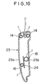
- FIG. 10 is a cross sectional view of a front door 23.
- the energy absorber 1 is attached to a shoulder portion 14.
- the location where the energy absorber 1 is attached may be on the outer panel 23 side as shown in the figure.
- the energy absorber 1 may be fixed to a reinforcement 24 as an inner panel. If the strength on the inner panel 23 side is increased, the deformation of the body can be suppressed by the inner panel 23.
- the energy absorber 1 may be attached to the inner panel side to absorb the energy when occupants are hit against the door to protect the occupants. In this case, the material of the energy absorber 1 is adjusted to be thin as a shock absorber.
- the impact energy absorbers 3 and 4 in an elliptic shape shown in FIGS. 4A and 4B are effective when they are arranged in a space having a small thickness. Furthermore, when the panel face to be attached is a plane, the contact area with the attached panel face becomes wide, thereby the impact energy absorber fits in well with the panel face and can be attached thereto strongly by an adhesive or by welding.
- the impact energy absorber 5 in a triangular shape shown in FIG. 5A is reinforced by providing concaves and convexes (not shown) on the surface.
- three sides of triangle function like truss, and even if load W is applied, the strength until the energy absorber is completely deformed plastically becomes high, and it becomes possible to lighten the weight of an automobile further by making the thickness of the impact energy absorber small.
- the angle is acute, the energy absorber is easy to be cracked. Therefore, by making the angle round, crack can be prevented.
- the oblique sides of the trapezoidal shape can absorb large energy until they are deformed plastically under load.
- other polygons they can be used for applications as the impact energy absorber, according to the characteristics due to their shapes.
- the energy absorber in accordance with the embodiment of the present invention which has concaves and convexes on the peripheral face of the pipe can absorb large energy. Therefore, when an external force is applied to the body of an automobile 11, the energy absorber 1 undergoes plastic deformation to absorb the energy of the external force, as shown in FIG. 1B, so that it can alleviate the burden and impact applied to other portions of the automobile 11.
- the energy absorber undergoes plastic deformation so that it can absorb the kinetic energy of the occupants when the occupants are hit against the vehicle body to alleviate the injury.
- the energy absorber 1 has versatility such that it can be attached to a somewhat curved location by been deformed accordingly, therefore its attaching workability is high. Its weight is light though its strength is high, so that it does not increase the weight of vehicle body so much.
- the energy absorbers 1 are arranged at the locations shown in FIG. 7, but the arrangement locations of the energy absorber 1 are not limited to the aforementioned locations.
- the energy absorbers 1 may be arranged on the inside of the bumper, as well as on a body shell such as a side shell, apron side panel or front panel of an engine room with similar effects.
- the attaching method of the energy absorber 1 it is bonded by an adhesive or by welding in the embodiment of the present invention, but it may be attached to the panel by installing clips on the absorber, or may be attached using a clip band.
- concaves and convexes 1a, 1b of the energy absorber 1 they are in a ripple form in the present invention, but rectangular concaves and convexes in a spiral-shape can get the similar effects.
- veining of concaves and convexes it need not be continuous, and thickness t, height of the peak of convexes 1b, depth of concaves 1a, and pitch p need not be the same.
- the energy absorber can absorb the energy of an external force applied to the body without an appreciable increase in weight of a vehicle body, and can alleviate the shock of occupants and damage to other components caused by the external force.
- the energy absorber can absorb the kinetic energy when occupants are hit against the body due to the external force applied to the body so that injury of occupants can be alleviated.
Landscapes
- Engineering & Computer Science (AREA)
- Mechanical Engineering (AREA)
- Chemical & Material Sciences (AREA)
- Combustion & Propulsion (AREA)
- Transportation (AREA)
- Vibration Dampers (AREA)
- Body Structure For Vehicles (AREA)
Abstract
An object of the present invention is to efficiently
absorb the energy of an external force applied to a vehicle
body without an appreciable increase in weight of an
automobile. The impact energy absorber is a metal pipe whose
cross section is circular, and provided with concaves and
convexes on both of the front and back surfaces in a spiral
form or bellows form. This energy absorber is bonded to the
room-side surface of an outer panel of the vehicle body or the
inner panel using an adhesive or the like. When an external
force is applied to the energy absorber through the panel face
of the vehicle body, the energy absorber can absorb the energy
of the external force by being deformed plastically. At this
time, when occupants are hit against the panel and the like and
indirectly against the energy absorber, the energy absorber can
absorb the kinetic energy of occupants by being deformed
plastically.
Description
The present invention relates to an impact energy
absorber for absorbing the energy of an external force applied
to an automotive body, and an impact energy absorber as a
protection for occupants against impact in the vehicle.
To ensure the safety of an automobile, a body panel such
as an outer panel and inner panel has so far been reinforced.
To reinforce the body panel, the thickness of panel is
increased. When the thickness of panel is increased, however,
the weight of a vehicle body increases accordingly. As a
result, the manufacturing cost as well as the material cost
increases, and the fuel consumption becomes high when the
automobile is run. Therefore, in designing the body panel,
consideration is made to fully increase the strength of panel
by considering the curvature, thickness and the like of the
panel.
Sometimes, however, it is difficult to make design
because the automotive body requires a different shape and
thickness according to the vehicle type, or the body cannot be
reinforced by an inner panel because automotive accessories are
disposed. Therefore, even if attempt is made to strengthen the
body while achieving the lightening of the same, it is
difficult to strengthen all portions, and some reinforcement
member is required. Also, there is a case where it is desired
to further strengthen the body by a simple method while
suppressing the increase in weight even if the body has been
strengthened fully in designing.
On the other hand, when an external force over a certain
value is applied to the automotive body, the body panel
undergoes plastic deformation. In such a case, if an absorber
is provided to absorb the energy of the external force, the
impact of occupants of the automobile and the damage to other
components due to the external force can be alleviated.
The present invention was made to solve the above
problems, and an object thereof is to provide an impact energy
absorber which can absorb the energy of an external force
applied to a body effectively without an appreciable increase
in weight of an automobile.
Furthermore, another object of the present invention is
to provide an impact energy absorber for absorbing the kinetic
energy of the occupants, when the occupants in the automobile
hit on the automotive body (pillar, roof and the like).
To achieve the above object, the present invention
provides an impact energy absorber which is a metallic pipe
provided with concaves and convexes integrally molded on the
front and back surfaces and disposed in a space provided
between a body outer panel which forms the external face of an
automobile and a body inner panel, with the peripheral face of
the pipe being mounted with a mounting member facing said both
panel surfaces to absorb the energy of an external force by
being deformed plastically when an external force is applied to
the pipe.
Thereby, the impact energy absorber absorbs an external
force when the external force is applied from outside of the
automotive body, and absorbs the kinetic energy of the
occupants when the occupants are hit against the inner panel or
the like.
An impact energy absorber in accordance with an
embodiment of the present invention will be described with
reference to the drawings.
FIGS. 1 and 2 show an impact energy absorber 1 in
accordance with the present invention. This energy absorber 1
is mainly used as a reinforcing material for an automotive body
and a protection material for occupants. As shown in FIG. 2A,
the impact energy absorber 1 is a metallic pipe having a
substantially circular lateral (radial) cross section. And as
shown in FIGS. 2B and 2C, concaves and convexes 1a and 1b in a
wave-form (or in a corrugated form) are integrally formed on
both front and back faces.
Furthermore, the impact energy absorber 1 has a thickness
t which is a certain thickness as a whole, and the shapes of
concaves and convexes 1a and 1b on the both front and back
faces are in a bellows shape in which annular concaves 1a and
convexes 1b are arranged alternately in the axial direction and
in parallel. The shapes of each peak and trough of respective
concaves 1a and convexes 1b are all the same, and the
corrugated pitch p is the same for each peak. The pipe axis of
the impact energy absorber 1 is made flexible by means of
concaves 1a and convexes 1b so that it can be bent in a S-shape.
As the material of the impact energy absorber 1,
various metals such as iron, copper, aluminum and stainless may
be used.
The impact energy absorber may have various shapes other
than the above-mentioned shapes.
The impact energy absorbers 2 shown in FIG. 3A to 3C are
basically the same as the impact energy absorber 1 described
above, but are different in that concaves and convexes 2a, 2b
on the pipe face extend in the axial direction of the pipe in
a spiral form. Other shapes, that is, the height of the peak
and the depth of the trough of each concave 2a and convex 2b,
and the length of corrugated pitch p are the same as those of
the impact energy absorber 1 described above.
The impact energy absorbers 3 and 4 shown in FIGS. 4A and
4B have a cross section in an elliptic form, and convexes 3b
and 4b on the bottom face and the upper face form planes. The
impact energy absorber 4 shown in FIG. 4A is formed in an
elliptic form from the beginning, and the impact energy
absorber 5 shown in FIG. 4B is formed in a circular form at the
initial stage, and then it is formed into an elliptic form by
pressing vertically, and therefore, convexes 4b are crashed.
As shown in FIG. 5, as the shapes of the impact energy
absorber, various shapes can be considered. The impact energy
absorber 5 shown in FIG. 5A is in a triangular shape, and the
impact energy absorber 6 shown in FIG. 5B is in a substantially
quadrangular shape, and the impact energy absorber 7 shown in
FIG. 5C is in a pentagonal shape. However, it may be formed
into a hexagonal shape or other polygonal shapes.
The characteristics of the impact energy absorber 1 will
now be described.
As shown in FIG. 6, the impact energy absorber 1
described above was compressed by the tip of a hemisphere 10
having a diameter of 165 mm by using a compression tester, and
the inside length L in FIG. 2A was measured until the
deformation amount becomes 0 mm. The compression speed was 100
mm/min.
The result is shown in FIG. 7, wherein the solid line a
indicates the test result for the impact energy absorber 1, and
the solid line b indicates the test result for the impact
energy absorber in a comparative example which is the same
circular pipe as the impact energy absorber 1 with the same
material, length, outer shape and thickness, but does not have
concaves and convexes on the periphery of the pipe.
As shown in FIG. 7, the energy absorber 1 provided with
concaves and convexes 1a, 1b is deformed less under a high load
at the initial stage than the one in the comparative example,
absorbing energy from an external force at the initial stage of
deformation. When a load over a certain value is applied, the
deformation increases suddenly. On the other hand, the energy
absorber in the comparative example exhibits a linear
relationship such that deformation is proportional to load.
Next, how to use the impact energy absorber 1 will be
described in a concrete example.
This energy absorber 1 absorbs the energy of an external
force applied to the body of an automobile, or absorbs the
kinetic energy of the occupants as a shock absorber to protect
the occupants. The arrangement locations of the energy
absorber 1 include, as shown in FIG. 8, a front pillar 12,
center pillar 13, shoulder portions 14 and 15 and lower
portions 16 and 17 of front and rear doors, front roof rail 18,
side roof rail 19, and rear header rail 20 of an automobile 11.
When a sliding roof is attached, the energy absorber can be
arranged around the sliding roof 21.
FIG. 9 shows a state in which the energy absorber 1 is
attached to the front pillar rail 12, center pillar rail 13 and
side roof rail 19, which are inside panels. The energy
absorber 1 is flexible because of concaves and convexes 1a, 1b,
and can be attached even if the arrangement location is
somewhat curved. Thereafter, the energy absorber 1 is arranged
at respective locations by fixing respective rails 12, 13 and
19 to the side body panel 22 which is the outer panel of the
automobile 11 by welding or by an adhesive.
FIG. 10 is a cross sectional view of a front door 23. As
described above, the energy absorber 1 is attached to a
shoulder portion 14. The location where the energy absorber 1
is attached may be on the outer panel 23 side as shown in the
figure. Furthermore, when the strength should be increased or
when the burden of the weight need not be considered, the
energy absorber 1 may be fixed to a reinforcement 24 as an
inner panel. If the strength on the inner panel 23 side is
increased, the deformation of the body can be suppressed by the
inner panel 23. Furthermore, the energy absorber 1 may be
attached to the inner panel side to absorb the energy when
occupants are hit against the door to protect the occupants.
In this case, the material of the energy absorber 1 is adjusted
to be thin as a shock absorber.
The impact energy absorbers 3 and 4 in an elliptic shape
shown in FIGS. 4A and 4B are effective when they are arranged
in a space having a small thickness. Furthermore, when the
panel face to be attached is a plane, the contact area with the
attached panel face becomes wide, thereby the impact energy
absorber fits in well with the panel face and can be attached
thereto strongly by an adhesive or by welding.
The impact energy absorber 5 in a triangular shape shown
in FIG. 5A is reinforced by providing concaves and convexes
(not shown) on the surface. In addition, three sides of
triangle function like truss, and even if load W is applied,
the strength until the energy absorber is completely deformed
plastically becomes high, and it becomes possible to lighten
the weight of an automobile further by making the thickness of
the impact energy absorber small. However, if the angle is
acute, the energy absorber is easy to be cracked. Therefore,
by making the angle round, crack can be prevented.
Regarding the impact energy absorber 6 having a cross
section in a trapezoidal shape shown in FIG. 5B, the oblique
sides of the trapezoidal shape can absorb large energy until
they are deformed plastically under load. Regarding other
polygons, they can be used for applications as the impact
energy absorber, according to the characteristics due to their
shapes.
As described above, the energy absorber in accordance
with the embodiment of the present invention which has concaves
and convexes on the peripheral face of the pipe can absorb
large energy. Therefore, when an external force is applied to
the body of an automobile 11, the energy absorber 1 undergoes
plastic deformation to absorb the energy of the external force,
as shown in FIG. 1B, so that it can alleviate the burden and
impact applied to other portions of the automobile 11.
Moreover, the energy absorber undergoes plastic
deformation so that it can absorb the kinetic energy of the
occupants when the occupants are hit against the vehicle body
to alleviate the injury.
Furthermore, the energy absorber 1 has versatility such
that it can be attached to a somewhat curved location by been
deformed accordingly, therefore its attaching workability is
high. Its weight is light though its strength is high, so that
it does not increase the weight of vehicle body so much.
Although one embodiment of the present invention has been
described above, needless to say, the present invention is not
limited to this embodiment. Various modifications may be made
based on the technical concept of the present invention.
For example, according to the above-mentioned embodiment,
the energy absorbers 1 are arranged at the locations shown in
FIG. 7, but the arrangement locations of the energy absorber 1
are not limited to the aforementioned locations. For example,
the energy absorbers 1 may be arranged on the inside of the
bumper, as well as on a body shell such as a side shell, apron
side panel or front panel of an engine room with similar
effects. With respect to the attaching method of the energy
absorber 1, it is bonded by an adhesive or by welding in the
embodiment of the present invention, but it may be attached to
the panel by installing clips on the absorber, or may be
attached using a clip band.
As for the shapes of concaves and convexes 1a, 1b of the
energy absorber 1, they are in a ripple form in the present
invention, but rectangular concaves and convexes in a spiral-shape
can get the similar effects. As for the veining of
concaves and convexes, it need not be continuous, and thickness
t, height of the peak of convexes 1b, depth of concaves 1a, and
pitch p need not be the same.
The same thing can be said of polygonal impact energy
absorbers.
As described above, the energy absorber can absorb the
energy of an external force applied to the body without an
appreciable increase in weight of a vehicle body, and can
alleviate the shock of occupants and damage to other components
caused by the external force.
Furthermore, the energy absorber can absorb the kinetic
energy when occupants are hit against the body due to the
external force applied to the body so that injury of occupants
can be alleviated.
Claims (4)
- An impact energy absorber which is a metallic pipe provided with concaves and convexes integrally formed on the front and back surfaces and disposed in a space provided between a body outer panel which forms the external face of an automobile and a body inner panel, with the peripheral face of said pipe being mounted with a mounting member facing said both panel surfaces to absorb the energy of an external force by being deformed plastically when an external force is applied to said pipe.
- An impact energy absorber according to claim 1, wherein the cross section of said pipe is substantially circular, and concaves and convexes are in a spiral form extending in the axial direction of said pipe, or they are in a bellows form in which concaves and convexes are alternately arranged in the axial direction of said pipe.
- An impact energy absorber according to claim 1, wherein the cross section of said pipe is substantially polygonal, and concaves and convexes are in a spiral form extending in the axial direction of said pipe, or they are in a bellows form in which concaves and convexes are alternately arranged in the axial direction of said pipe.
- An impact energy absorber according to claim 3, wherein the angles of said polygonal pipe are rounded.
Applications Claiming Priority (2)
| Application Number | Priority Date | Filing Date | Title |
|---|---|---|---|
| JP17554697 | 1997-07-01 | ||
| JP175546/97 | 1997-07-01 |
Publications (1)
| Publication Number | Publication Date |
|---|---|
| EP0888952A1 true EP0888952A1 (en) | 1999-01-07 |
Family
ID=15997976
Family Applications (1)
| Application Number | Title | Priority Date | Filing Date |
|---|---|---|---|
| EP97250282A Withdrawn EP0888952A1 (en) | 1997-07-01 | 1997-09-18 | Impact energy absorber |
Country Status (2)
| Country | Link |
|---|---|
| EP (1) | EP0888952A1 (en) |
| CA (1) | CA2219733A1 (en) |
Cited By (11)
| Publication number | Priority date | Publication date | Assignee | Title |
|---|---|---|---|---|
| EP0955227A3 (en) * | 1998-05-08 | 2000-04-19 | Toyota Jidosha Kabushiki Kaisha | Impact energy absorbing structure in upper vehicle body portion and impact energy absorbing member |
| GB2382805A (en) * | 2001-12-06 | 2003-06-11 | Lear Corp | Impact absorbing member for vehicle |
| EP1176061A3 (en) * | 2000-07-27 | 2003-10-29 | Takata Corporation | Airbag apparatus |
| EP1437265A1 (en) * | 2003-01-08 | 2004-07-14 | Ohtsuka Co., Ltd. | Impact energy absorber |
| EP1892159A2 (en) | 2006-08-10 | 2008-02-27 | O-Flex Group Inc. | Corrugated tubular energy absorbing structure. |
| US7338038B2 (en) | 2004-03-12 | 2008-03-04 | Dow Global Technologies, Inc. | Impact absorption structure |
| CN101314349B (en) * | 2007-06-01 | 2012-08-22 | 奇瑞汽车股份有限公司 | Energy-absorbing device of bumper |
| CN103448806A (en) * | 2012-06-04 | 2013-12-18 | 现代自动车株式会社 | Apparatus for reducing injury to passenger' feet during offset crash |
| WO2021244792A1 (en) * | 2020-06-04 | 2021-12-09 | Autotech Engineering S.L. | A vehicle structure |
| CN115279649A (en) * | 2020-03-09 | 2022-11-01 | 昂登坦汽车工程有限责任公司 | Vehicle structure |
| RU2827262C1 (en) * | 2020-06-04 | 2024-09-23 | Аутотек Инжиниринг С.Л. | Vehicle structure |
Citations (6)
| Publication number | Priority date | Publication date | Assignee | Title |
|---|---|---|---|---|
| AU3373271A (en) * | 1971-09-21 | 1973-03-29 | John Osborne Miller Douglas | Absorbing girdle |
| EP0266084A2 (en) * | 1986-10-27 | 1988-05-04 | Mitsui & Co., Ltd. | Shock absorbing member for car body |
| EP0464974A1 (en) * | 1990-07-02 | 1992-01-08 | MANNESMANN Aktiengesellschaft | Impact beam for door |
| DE4211964A1 (en) * | 1992-04-09 | 1993-10-14 | Daimler Benz Ag | Corrugated tubular impact absorber - has closer spaced corrugations in areas of large deformation forces |
| DE9218388U1 (en) * | 1992-10-31 | 1994-02-24 | Julius & August Erbslöh GmbH & Co, 42553 Velbert | Door impact beam for motor vehicle bodies |
| DE19514324A1 (en) * | 1994-04-18 | 1995-12-07 | Nissan Motor | Upper frontal construction for motor vehicles |
-
1997
- 1997-09-18 EP EP97250282A patent/EP0888952A1/en not_active Withdrawn
- 1997-10-30 CA CA 2219733 patent/CA2219733A1/en not_active Abandoned
Patent Citations (6)
| Publication number | Priority date | Publication date | Assignee | Title |
|---|---|---|---|---|
| AU3373271A (en) * | 1971-09-21 | 1973-03-29 | John Osborne Miller Douglas | Absorbing girdle |
| EP0266084A2 (en) * | 1986-10-27 | 1988-05-04 | Mitsui & Co., Ltd. | Shock absorbing member for car body |
| EP0464974A1 (en) * | 1990-07-02 | 1992-01-08 | MANNESMANN Aktiengesellschaft | Impact beam for door |
| DE4211964A1 (en) * | 1992-04-09 | 1993-10-14 | Daimler Benz Ag | Corrugated tubular impact absorber - has closer spaced corrugations in areas of large deformation forces |
| DE9218388U1 (en) * | 1992-10-31 | 1994-02-24 | Julius & August Erbslöh GmbH & Co, 42553 Velbert | Door impact beam for motor vehicle bodies |
| DE19514324A1 (en) * | 1994-04-18 | 1995-12-07 | Nissan Motor | Upper frontal construction for motor vehicles |
Cited By (26)
| Publication number | Priority date | Publication date | Assignee | Title |
|---|---|---|---|---|
| US6199941B1 (en) | 1998-05-08 | 2001-03-13 | Toyota Jidosha Kabushiki Kaisha | Impact energy absorbing structure in upper vehicle body portion and impact energy absorbing member |
| US6293614B1 (en) | 1998-05-08 | 2001-09-25 | Toyota Jidosha Kabushiki Kaisha | Impact energy absorbing structure in upper vehicle body portion and impact energy absorbing member |
| EP0955227A3 (en) * | 1998-05-08 | 2000-04-19 | Toyota Jidosha Kabushiki Kaisha | Impact energy absorbing structure in upper vehicle body portion and impact energy absorbing member |
| EP1176061A3 (en) * | 2000-07-27 | 2003-10-29 | Takata Corporation | Airbag apparatus |
| GB2382805A (en) * | 2001-12-06 | 2003-06-11 | Lear Corp | Impact absorbing member for vehicle |
| US6779835B2 (en) | 2001-12-06 | 2004-08-24 | Lear Corporation | Energy absorbing structure for automobile interior |
| GB2382805B (en) * | 2001-12-06 | 2005-03-16 | Lear Corp | Energy absorbing structure for automobile interior |
| EP1437265A1 (en) * | 2003-01-08 | 2004-07-14 | Ohtsuka Co., Ltd. | Impact energy absorber |
| US7513344B2 (en) | 2004-03-12 | 2009-04-07 | Dow Global Technologies, Inc. | Impact absorption structure |
| US7338038B2 (en) | 2004-03-12 | 2008-03-04 | Dow Global Technologies, Inc. | Impact absorption structure |
| US7963378B2 (en) | 2006-08-10 | 2011-06-21 | O-Flex Group, Inc. | Corrugated tubular energy absorbing structure |
| EP1892159A3 (en) * | 2006-08-10 | 2008-03-05 | O-Flex Group Inc. | Corrugated tubular energy absorbing structure. |
| EP1892159A2 (en) | 2006-08-10 | 2008-02-27 | O-Flex Group Inc. | Corrugated tubular energy absorbing structure. |
| CN101314349B (en) * | 2007-06-01 | 2012-08-22 | 奇瑞汽车股份有限公司 | Energy-absorbing device of bumper |
| CN103448806A (en) * | 2012-06-04 | 2013-12-18 | 现代自动车株式会社 | Apparatus for reducing injury to passenger' feet during offset crash |
| CN103448806B (en) * | 2012-06-04 | 2016-12-21 | 现代自动车株式会社 | The device of period passenger's foot injury is hit for reducing front angle collision |
| CN115279649A (en) * | 2020-03-09 | 2022-11-01 | 昂登坦汽车工程有限责任公司 | Vehicle structure |
| CN115279649B (en) * | 2020-03-09 | 2023-12-22 | 昂登坦汽车工程有限责任公司 | vehicle structure |
| WO2021244792A1 (en) * | 2020-06-04 | 2021-12-09 | Autotech Engineering S.L. | A vehicle structure |
| CN115667057A (en) * | 2020-06-04 | 2023-01-31 | 昂登坦汽车工程有限责任公司 | vehicle structure |
| US20230202564A1 (en) * | 2020-06-04 | 2023-06-29 | Autotech Engineering S.L. | A vehicle structure |
| EP4431372A1 (en) * | 2020-06-04 | 2024-09-18 | Autotech Engineering S.L. | A vehicle structure |
| RU2827262C1 (en) * | 2020-06-04 | 2024-09-23 | Аутотек Инжиниринг С.Л. | Vehicle structure |
| US12344308B2 (en) * | 2020-06-04 | 2025-07-01 | Autotech Engineering S.L. | Vehicle structure |
| EP4549291A3 (en) * | 2020-06-04 | 2025-07-02 | Autotech Engineering S.L. | A vehicle structure |
| CN115667057B (en) * | 2020-06-04 | 2025-11-14 | 昂登坦汽车工程有限责任公司 | Vehicle structure |
Also Published As
| Publication number | Publication date |
|---|---|
| CA2219733A1 (en) | 1999-01-01 |
Similar Documents
| Publication | Publication Date | Title |
|---|---|---|
| US5680886A (en) | Impact energy absorber | |
| KR19980018667A (en) | Method of forming transparent window in polishing pad for chemical mechanical polishing device | |
| US5833024A (en) | Automotive hood structure | |
| JPWO2018021421A1 (en) | Car exterior panel | |
| CN111629921A (en) | Shock Absorber | |
| CN100391775C (en) | car hood | |
| JP6717378B2 (en) | Shock absorber | |
| CA2219733A1 (en) | Impact energy absorber | |
| CN100379594C (en) | Component for automobile structure and automobile body using the same | |
| JPH06101732A (en) | Shock absorbing member for composite structure | |
| US5203436A (en) | Reinforced tubular door support | |
| EP1437265A1 (en) | Impact energy absorber | |
| JPH1170886A (en) | Impact energy absorbing material and its absorbing structure | |
| KR20240098632A (en) | Frame for Electric vehicle | |
| JP3091734B2 (en) | Impact energy absorber | |
| CN111989241B (en) | Carrier elements, fixtures and vehicles | |
| JP7381963B2 (en) | Stiffening structure of panel parts | |
| JP2750456B2 (en) | Metal bellows tube | |
| JP3845419B2 (en) | Impact energy absorber | |
| GB2434125A (en) | Sheet member with part-conical elements providing impact protection | |
| JP2008110679A (en) | Automotive bumper reinforcement | |
| JPH10278707A (en) | Automotive bumper reinforcement | |
| JP2000108663A (en) | Impact beam | |
| JPH11348818A (en) | Automotive shock absorbing member and structure | |
| JP2000103306A (en) | Structure for fixing hollow shock absorber and resin body to structural member of vehicle body and shock absorbing component |
Legal Events
| Date | Code | Title | Description |
|---|---|---|---|
| PUAI | Public reference made under article 153(3) epc to a published international application that has entered the european phase |
Free format text: ORIGINAL CODE: 0009012 |
|
| AK | Designated contracting states |
Kind code of ref document: A1 Designated state(s): AT BE CH DE DK ES FI FR GB GR IE IT LI LU MC NL PT SE |
|
| AX | Request for extension of the european patent |
Free format text: AL;LT;LV;RO;SI |
|
| AKX | Designation fees paid | ||
| STAA | Information on the status of an ep patent application or granted ep patent |
Free format text: STATUS: THE APPLICATION IS DEEMED TO BE WITHDRAWN |
|
| 18D | Application deemed to be withdrawn |
Effective date: 19990708 |
|
| REG | Reference to a national code |
Ref country code: DE Ref legal event code: 8566 |