EP0887526B1 - Direct injection type engine and cooling system therefor - Google Patents
Direct injection type engine and cooling system therefor Download PDFInfo
- Publication number
- EP0887526B1 EP0887526B1 EP98111804A EP98111804A EP0887526B1 EP 0887526 B1 EP0887526 B1 EP 0887526B1 EP 98111804 A EP98111804 A EP 98111804A EP 98111804 A EP98111804 A EP 98111804A EP 0887526 B1 EP0887526 B1 EP 0887526B1
- Authority
- EP
- European Patent Office
- Prior art keywords
- combustion
- cooling
- radiator
- fuel
- current
- Prior art date
- Legal status (The legal status is an assumption and is not a legal conclusion. Google has not performed a legal analysis and makes no representation as to the accuracy of the status listed.)
- Expired - Lifetime
Links
- 238000001816 cooling Methods 0.000 title claims description 27
- 238000002347 injection Methods 0.000 title description 17
- 239000007924 injection Substances 0.000 title description 17
- 238000002485 combustion reaction Methods 0.000 claims description 88
- 239000000446 fuel Substances 0.000 claims description 71
- XLYOFNOQVPJJNP-UHFFFAOYSA-N water Substances O XLYOFNOQVPJJNP-UHFFFAOYSA-N 0.000 claims description 38
- 239000000203 mixture Substances 0.000 claims description 29
- 239000000498 cooling water Substances 0.000 claims description 18
- 230000007423 decrease Effects 0.000 claims description 4
- 230000006835 compression Effects 0.000 description 12
- 238000007906 compression Methods 0.000 description 12
- 238000010790 dilution Methods 0.000 description 3
- 239000012895 dilution Substances 0.000 description 3
- 238000005461 lubrication Methods 0.000 description 3
- 238000013021 overheating Methods 0.000 description 3
- 238000000889 atomisation Methods 0.000 description 2
- 238000010276 construction Methods 0.000 description 2
- 238000000034 method Methods 0.000 description 2
- 230000002457 bidirectional effect Effects 0.000 description 1
- 230000006870 function Effects 0.000 description 1
- 238000012986 modification Methods 0.000 description 1
- 230000004048 modification Effects 0.000 description 1
- 238000011144 upstream manufacturing Methods 0.000 description 1
Images



Classifications
-
- F—MECHANICAL ENGINEERING; LIGHTING; HEATING; WEAPONS; BLASTING
- F01—MACHINES OR ENGINES IN GENERAL; ENGINE PLANTS IN GENERAL; STEAM ENGINES
- F01P—COOLING OF MACHINES OR ENGINES IN GENERAL; COOLING OF INTERNAL-COMBUSTION ENGINES
- F01P7/00—Controlling of coolant flow
- F01P7/14—Controlling of coolant flow the coolant being liquid
- F01P7/16—Controlling of coolant flow the coolant being liquid by thermostatic control
- F01P7/167—Controlling of coolant flow the coolant being liquid by thermostatic control by adjusting the pre-set temperature according to engine parameters, e.g. engine load, engine speed
-
- F—MECHANICAL ENGINEERING; LIGHTING; HEATING; WEAPONS; BLASTING
- F02—COMBUSTION ENGINES; HOT-GAS OR COMBUSTION-PRODUCT ENGINE PLANTS
- F02B—INTERNAL-COMBUSTION PISTON ENGINES; COMBUSTION ENGINES IN GENERAL
- F02B17/00—Engines characterised by means for effecting stratification of charge in cylinders
- F02B17/005—Engines characterised by means for effecting stratification of charge in cylinders having direct injection in the combustion chamber
-
- F—MECHANICAL ENGINEERING; LIGHTING; HEATING; WEAPONS; BLASTING
- F01—MACHINES OR ENGINES IN GENERAL; ENGINE PLANTS IN GENERAL; STEAM ENGINES
- F01P—COOLING OF MACHINES OR ENGINES IN GENERAL; COOLING OF INTERNAL-COMBUSTION ENGINES
- F01P3/00—Liquid cooling
- F01P3/02—Arrangements for cooling cylinders or cylinder heads
- F01P2003/021—Cooling cylinders
-
- F—MECHANICAL ENGINEERING; LIGHTING; HEATING; WEAPONS; BLASTING
- F01—MACHINES OR ENGINES IN GENERAL; ENGINE PLANTS IN GENERAL; STEAM ENGINES
- F01P—COOLING OF MACHINES OR ENGINES IN GENERAL; COOLING OF INTERNAL-COMBUSTION ENGINES
- F01P3/00—Liquid cooling
- F01P3/02—Arrangements for cooling cylinders or cylinder heads
- F01P2003/024—Cooling cylinder heads
-
- F—MECHANICAL ENGINEERING; LIGHTING; HEATING; WEAPONS; BLASTING
- F01—MACHINES OR ENGINES IN GENERAL; ENGINE PLANTS IN GENERAL; STEAM ENGINES
- F01P—COOLING OF MACHINES OR ENGINES IN GENERAL; COOLING OF INTERNAL-COMBUSTION ENGINES
- F01P2025/00—Measuring
- F01P2025/60—Operating parameters
- F01P2025/62—Load
-
- F—MECHANICAL ENGINEERING; LIGHTING; HEATING; WEAPONS; BLASTING
- F01—MACHINES OR ENGINES IN GENERAL; ENGINE PLANTS IN GENERAL; STEAM ENGINES
- F01P—COOLING OF MACHINES OR ENGINES IN GENERAL; COOLING OF INTERNAL-COMBUSTION ENGINES
- F01P2025/00—Measuring
- F01P2025/60—Operating parameters
- F01P2025/64—Number of revolutions
-
- F—MECHANICAL ENGINEERING; LIGHTING; HEATING; WEAPONS; BLASTING
- F02—COMBUSTION ENGINES; HOT-GAS OR COMBUSTION-PRODUCT ENGINE PLANTS
- F02B—INTERNAL-COMBUSTION PISTON ENGINES; COMBUSTION ENGINES IN GENERAL
- F02B75/00—Other engines
- F02B75/12—Other methods of operation
- F02B2075/125—Direct injection in the combustion chamber for spark ignition engines, i.e. not in pre-combustion chamber
-
- Y—GENERAL TAGGING OF NEW TECHNOLOGICAL DEVELOPMENTS; GENERAL TAGGING OF CROSS-SECTIONAL TECHNOLOGIES SPANNING OVER SEVERAL SECTIONS OF THE IPC; TECHNICAL SUBJECTS COVERED BY FORMER USPC CROSS-REFERENCE ART COLLECTIONS [XRACs] AND DIGESTS
- Y02—TECHNOLOGIES OR APPLICATIONS FOR MITIGATION OR ADAPTATION AGAINST CLIMATE CHANGE
- Y02T—CLIMATE CHANGE MITIGATION TECHNOLOGIES RELATED TO TRANSPORTATION
- Y02T10/00—Road transport of goods or passengers
- Y02T10/10—Internal combustion engine [ICE] based vehicles
- Y02T10/12—Improving ICE efficiencies
Definitions
- the present invention relates to a cooling device for an internal combustion engine with a fuel injector for injecting fuel directly into the cylinder, in which a current combustion is changed between pre-mixture combustion and stratified charge combustion in accordance with a current engine operating condition.
- the engine in which the stratified charge combustion and the pre-mixture combustion are alternated is usually cooled by cooling water.
- the same cooling system is used, which has a passage in which cooling water circulates and a radiator in which heat of cooling water releases.
- the cooling system is adapted to the pre-mixture combustion. Therefore, an excess cooling occurs during the stratified charge combustion.
- a combustible gas mixture is formed only close to the ignition plug and thus combustion is carried out. Accordingly, the time from fuel injection to ignition is short.
- the temperature of the engine block is made low by the cooling so that injected fuel can not vaporize sufficiently in the short time. Therefore, a discharged amount of unburned fuel (HC) can increase.
- HC unburned fuel
- HC unburned fuel
- HC unburned fuel
- a difference in temperature between the center portion and the periphery portion of the piston becomes large so that a deformation of the piston is easily caused and thus scuffing of the piston can occur.
- an object of the present invention is to provide an internal combustion engine with a fuel injector for injecting fuel directly into the cylinder, which can prevent an excess cooling of the engine body at the stratified charge combustion and can guarantee a sufficient cooling of the engine body at the pre-mixture combustion.
- an internal combustion engine with a fuel injector for injecting fuel directly into the cylinder, in which a current combustion is changed between pre-mixture combustion and stratified charge combustion in accordance with a current engine operating condition, comprising varying means for varying flow condition of cooling water in a cooling system of the engine, according to said current combustion.
- Fig. 1 shows a general construction of an internal combustion engine with a fuel injector for injecting fuel directly into the cylinder according to an embodiment of the present invention.
- reference numeral 10 designates a cylinder-block in which the cylinder-bore 10-1 is formed.
- a piston 12 is arranged in the cylinder-bore and can slide vertically on the liner-surface thereof.
- a cylinder-head 14 is mounted on the cylinder-block 10.
- a combustion chamber 16 is formed by the cylinder-block 10 and the cylinder-head 14.
- An ignition plug 18 is arranged in the cylinder-head 14 and the electrodes thereof are directed into the combustion chamber 16.
- a fuel injector 20 is arranged in the cylinder-head 14 and the injection hole thereof 20-1 opens on the upper side of the combustion chamber 16.
- Intake valve 22 and exhaust valve 24 are arranged in the cylinder-head 14. The intake valve 22 opens and closes intake port 26 and the exhaust valve 24 opens and closes exhaust port 28.
- reference numeral 30 is a water passage for cooling the engine body, which is formed in the cylinder-block 10 at the opposite side of the fuel injector 20.
- Reference numeral 32 is a water passage for cooling the engine body, which is formed in the cylinder-block 10 at the side of the fuel injector 20.
- Reference numeral 34 is a water passage for cooling the engine body, which is formed in the cylinder-head.
- reference numeral 40 is a radiator which is connected to each entrance side of the water passages for cooling the engine body 30, 32, 34 via a water pump 42 and a water feed passage 44 on the lower side of the radiator. In a passage 44-1 by which the water feed passage 44 is connected with the water passage 30, a control valve 45 is arranged.
- the control valve 45 functions to vary the flow of cooling water from the water feed passage 44 to the water passage 30 in the cylinder-block 10.
- Each exit side (not shown) of the water passages 30, 32, 34 are connected with the entrance tank 40-1 of the radiator 40 via a water return passage 46 and a changing valve 48.
- a bypass passage 50 is provided between the changing valve 48 and the water pump 42.
- the changing valve 48 changes between a first position in which cooling water from the water return passage 46 flows into the radiator 40 and a second position in which cooling water from the water return passage 46 flows into the water pump 42 via the bypass passage 50 (i.e., cooling water bypasses the radiator 40).
- Reference numeral 70 designates an electronic control unit (ECU) for controlling the fuel injector 20, the control valve 45, and the changing valve 48.
- the ECU 70 is constructed as a digital computer and includes a ROM (read only memory) 72, a RAM (random access memory) 73, a CPU (microprocessor, etc.) 74, an input port 75, and an output port 76, which are interconnected by a bidirectional bus 71.
- An air-flow meter 81 which is arranged upstream of the throttle valve in the intake passage and detects an amount of intake air, is connected to the input port 75 via an AD converter 77.
- An engine speed sensor 82 which is arranged on the distributor and detects the engine speed, is connected to the input port 75.
- the output port 76 is connected to each fuel injector 20 via a drive circuit 78a, to the control valve 45 via a drive circuit 78b, and to the changing valve 48 via a drive circuit 78c.
- the ECU 70 controls the fuel injector 20 as follows, on the basis of a current engine load determined by an output of the air-flow meter 81.
- a current engine load is high, fuel injection is carried out during an intake stroke to realize a pre-mixture combustion.
- a current engine load is low, fuel injection is carried out during a compression stroke to realize a stratified charge combustion.
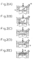
- Fig. 2 shows a fuel injection process for the pre-mixture combustion.
- Fig. 2(A) shows a middle stage in an intake stroke, in which the fuel injection starts.
- Fig. 2(B) shows a final stage in an intake stroke, in which the fuel injection stops.
- FIG. 2(C) shows an initial stage in a compression stroke, in which the injected fuel spreads in the combustion chamber.
- Fig. 2(D) shows a final stage in a compression stroke, in which the injected fuel is sufficiently mixed with intake air.
- Fig. 2(E) shows an ignition stage in which the piston 12 is close to a top dead center and the ignition plug 18 is actuated so that an ignition of the mixture is caused.
- Fig. 3 shows a fuel injection process for the stratified charge combustion.
- Fig. 3(A) shows a middle stage in an intake stroke.
- Fig. 3(B) shows a final stage in an intake stroke.
- Fig. 3(C) shows an initial stage in a compression stroke. In these stages, no fuel injection is carried out.
- Fig. 3(D) shows a final stage in a compression stroke, in which the fuel injection starts. The injected fuel converges close to the electrodes 18-1 of the ignition plug 18 and becomes a combustible gas mixture which exists only close thereto.
- Fig. 3(E) shows an ignition stage in which the piston 12 is close to a top dead center and the ignition plug 18 is actuated so that an ignition of the combustible gas mixture is caused.
- Fig. 4 is an enlarged view of Fig. 3(D). As shown in Fig. 4, the fuel injected by the fuel injector 20 stays close to the electrodes 18-1 of the ignition plug. Therefore, the electrodes 18-1 are not sufficiently heated in the stratified charge combustion and are cooled by the fuel so that a misfire can occur. Furthermore, due to excess cooling, friction forces in sliding portions of the engine increase. Fig.
- FIG. 5 is an enlarged view of Fig. 3(E), and shows the combustion condition.
- the combustion occurs only in an area (M) close to the electrodes 18-1 of the ignition plug. Namely, the combustion is limited in the center portion of the combustion chamber 16. Therefore, the tip portion of the fuel injector 20 is out of the combustion area, and thus a temperature of the tip portion of the fuel injector 20 becomes low. Accordingly, an atomization of fuel deteriorates and thus a discharged amount of unburned fuel increases. Furthermore, a difference temperature between the center portion 12-1 and the periphery portion 12-2 of the piston 12 is made large so that a thermal deformation of the piston 12 is easily caused and thus scuffing of the piston can occur.
- the ECU 70 controls the control valve 45 and the changing valve 48 according to a routine shown in Fig. 7.
- the routine is explained as follows. First, at step 100, it is determined if a current combustion is the stratified charge combustion. When the result is negative, i.e., the pre-mixture combustion is carried out, the routine goes to step 102 and the changing valve 48 is made the first position so that the water return passage 46 is connected to the radiator 40 and is separated from the bypass passage 50. Namely, as a water circuit shown in Fig.
- the cooling water from the water pump 42 passes through the water passage 30 at the opposite side of the fuel injector, the water passage 32 at the side of the fuel injector, the water passage 34 in the cylinder-head, and the radiator 40, and returns to the water pump 42.
- the control valve 45 is throttled and is made partly open. Therefore, a flow rate in the water passage 30 at the opposite side of the fuel injection becomes smaller than that in the water passage 32 at the side of the fuel injector.
- a temperature of the liner surface of the cylinder-bore at the opposite side of the fuel injector becomes higher than that at the side of the fuel injector.
- Fig. 6 is an enlarged view of Fig. 2(A), but shows a piston position which is slightly lower than that in Fig. 2(A).
- the injected fuel sticks easily to the liner surface (P) of the cylinder-bore at the opposite side of the fuel injection 20.
- the whole cylinder-block 10 must be sufficiently cooled and therefore the temperature of the liner surface (P) of the cylinder-bore at the opposite side of the fuel injector becomes relative low, the stuck fuel is easily mixed with lubrication oil on the liner surface and oil dilution can occur.
- the oil dilution decreases the viscosity of the lubrication oil and causes an insufficient lubrication.
- the temperature of the liner surface of the cylinder-bore at only the opposite side of the fuel injector, on which the injected fuel easily sticks is made high so that the above-mentioned oil dilution can be prevented.
- the liner surface of the cylinder-bore at the side of the fuel injector, on which the injected fuel hardly sticks is sufficiently cooled so that overheating can be prevented.
- step 106 when the result at step 100 is affirmative, i.e., the stratified charge combustion is carried out, the routine goes to step 106, and the changing valve 48 is made the second position so that the water return passage 46 is connected to the bypass passage 50 and is separated from the radiator 40.
- the cooling water from the water pump 42 passes through the water passage 30 at the opposite side of the fuel injector, the water passage 32 at the side of the fuel injector, the water passage 34 in the cylinder-head, and the bypass passage 50, and returns to the water pump 42.
- step 108 the control valve 45 is made fully open.
- a flow rate in the water passage 30 at the opposite side of the fuel injection is equal to that in the water passage 32 at the side of the fuel injector.
Landscapes
- Engineering & Computer Science (AREA)
- Chemical & Material Sciences (AREA)
- Combustion & Propulsion (AREA)
- Mechanical Engineering (AREA)
- General Engineering & Computer Science (AREA)
- Combustion Methods Of Internal-Combustion Engines (AREA)
- Electrical Control Of Air Or Fuel Supplied To Internal-Combustion Engine (AREA)
- Combined Controls Of Internal Combustion Engines (AREA)
Description
- The present invention relates to a cooling device for an internal combustion engine with a fuel injector for injecting fuel directly into the cylinder, in which a current combustion is changed between pre-mixture combustion and stratified charge combustion in accordance with a current engine operating condition.
- In a known internal combustion engine with a fuel injector for injecting gasoline fuel directly into the cylinder, fuel injection at a low engine load is carried out during a compression stroke so that a combustible gas mixture is formed only close to the spark plug and thus a stratified charge combustion is carried out. On the other hand, fuel injection at a high engine load is carried out during an intake stroke so that injected fuel is sufficiently mixed with intake air and thereafter pre-mixture combustion is carried out. Japanese Unexamined Patent Publication No. 5-52145 discloses an internal combustion engine in which fuel injection timing is changed, as above-mentioned, and whereby, at a low engine load, lean burn can be realized so that fuel consumption can be improved. On the other hand, at a high engine load, a required high engine output can be obtained. The engine in which the stratified charge combustion and the pre-mixture combustion are alternated is usually cooled by cooling water. During the stratified charge combustion and during the pre-mixture combustion, the same cooling system is used, which has a passage in which cooling water circulates and a radiator in which heat of cooling water releases.
- The cooling system is adapted to the pre-mixture combustion. Therefore, an excess cooling occurs during the stratified charge combustion. In the stratified charge combustion, a combustible gas mixture is formed only close to the ignition plug and thus combustion is carried out. Accordingly, the time from fuel injection to ignition is short. On the other hand, the temperature of the engine block is made low by the cooling so that injected fuel can not vaporize sufficiently in the short time. Therefore, a discharged amount of unburned fuel (HC) can increase. Moreover, if injected fuel can stick to the ignition plug, the fuel can not vaporize due to the low temperature of the engine block so that a misfire can occur. Furthermore, a difference in temperature between the center portion and the periphery portion of the piston becomes large so that a deformation of the piston is easily caused and thus scuffing of the piston can occur.
- Therefore, an object of the present invention is to provide an internal combustion engine with a fuel injector for injecting fuel directly into the cylinder, which can prevent an excess cooling of the engine body at the stratified charge combustion and can guarantee a sufficient cooling of the engine body at the pre-mixture combustion.
- According to the present invention, there is provided an internal combustion engine with a fuel injector for injecting fuel directly into the cylinder, in which a current combustion is changed between pre-mixture combustion and stratified charge combustion in accordance with a current engine operating condition, comprising varying means for varying flow condition of cooling water in a cooling system of the engine, according to said current combustion.
- The present invention will be more fully understood from the description of preferred embodiments of the invention set forth below, together with the accompanying drawings.
- In the drawings:
- Fig. 1 shows a general construction of an internal combustion engine with a fuel injector for injecting fuel directly into the cylinder according to an embodiment of the present invention;
- Fig. 2(A) shows a middle stage in an intake stroke at the pre-mixture combustion;
- Fig. 2(B) shows a final stage in an intake stroke at the pre-mixture combustion;
- Fig. 2(C) shows an initial stage in a compression stroke at the pre-mixture combustion;
- Fig. 2(D) shows a final stage in a compression stroke at the pre-mixture combustion;
- Fig. 2(E) shows an ignition stage in a compression stroke at the pre-mixture combustion;
- Fig. 3(A) shows a middle stage in an intake stroke at the stratified charge combustion;
- Fig. 3(B) shows a final stage in an intake stroke at the stratified charge combustion;
- Fig. 3(C) shows an initial stage in a compression stroke at the stratified charge combustion;
- Fig. 3(D) shows a final stage in a compression stroke at the stratified charge combustion;
- Fig. 3(E) shows an ignition stage in a compression stroke at the stratified charge combustion;
- Fig. 4 is an enlarged view of Fig. 3(D);
- Fig. 5 is an enlarged view of Fig. 3(E);
- Fig. 6 is an enlarged view of Fig. 2(A), in which a piston position is slightly lower than that in Fig. 2(A);
- Fig. 7 is a routine for controlling the changing valve and control valve;
- Fig. 8(A) shows a water circuit during pre-mixture combustion; and
- Fig. 8(B) shows a water circuit during stratified charge combustion.
-
- Fig. 1 shows a general construction of an internal combustion engine with a fuel injector for injecting fuel directly into the cylinder according to an embodiment of the present invention. In this figure,
reference numeral 10 designates a cylinder-block in which the cylinder-bore 10-1 is formed. Apiston 12 is arranged in the cylinder-bore and can slide vertically on the liner-surface thereof. A cylinder-head 14 is mounted on the cylinder-block 10. Acombustion chamber 16 is formed by the cylinder-block 10 and the cylinder-head 14. Anignition plug 18 is arranged in the cylinder-head 14 and the electrodes thereof are directed into thecombustion chamber 16. Afuel injector 20 is arranged in the cylinder-head 14 and the injection hole thereof 20-1 opens on the upper side of thecombustion chamber 16.Intake valve 22 andexhaust valve 24 are arranged in the cylinder-head 14. Theintake valve 22 opens and closesintake port 26 and theexhaust valve 24 opens and closesexhaust port 28. - In a cooling system,
reference numeral 30 is a water passage for cooling the engine body, which is formed in the cylinder-block 10 at the opposite side of thefuel injector 20.Reference numeral 32 is a water passage for cooling the engine body, which is formed in the cylinder-block 10 at the side of thefuel injector 20.Reference numeral 34 is a water passage for cooling the engine body, which is formed in the cylinder-head. On the other hand,reference numeral 40 is a radiator which is connected to each entrance side of the water passages for cooling theengine body water pump 42 and awater feed passage 44 on the lower side of the radiator. In a passage 44-1 by which thewater feed passage 44 is connected with thewater passage 30, acontrol valve 45 is arranged. Thecontrol valve 45 functions to vary the flow of cooling water from thewater feed passage 44 to thewater passage 30 in the cylinder-block 10. Each exit side (not shown) of thewater passages radiator 40 via awater return passage 46 and a changingvalve 48. Abypass passage 50 is provided between the changingvalve 48 and thewater pump 42. The changingvalve 48 changes between a first position in which cooling water from thewater return passage 46 flows into theradiator 40 and a second position in which cooling water from thewater return passage 46 flows into thewater pump 42 via the bypass passage 50 (i.e., cooling water bypasses the radiator 40). -
Reference numeral 70 designates an electronic control unit (ECU) for controlling thefuel injector 20, thecontrol valve 45, and the changingvalve 48. The ECU 70 is constructed as a digital computer and includes a ROM (read only memory) 72, a RAM (random access memory) 73, a CPU (microprocessor, etc.) 74, aninput port 75, and anoutput port 76, which are interconnected by abidirectional bus 71. An air-flow meter 81 which is arranged upstream of the throttle valve in the intake passage and detects an amount of intake air, is connected to theinput port 75 via anAD converter 77. Anengine speed sensor 82 which is arranged on the distributor and detects the engine speed, is connected to theinput port 75. Theoutput port 76 is connected to eachfuel injector 20 via adrive circuit 78a, to thecontrol valve 45 via adrive circuit 78b, and to the changingvalve 48 via adrive circuit 78c. - The
ECU 70 controls thefuel injector 20 as follows, on the basis of a current engine load determined by an output of the air-flow meter 81. When a current engine load is high, fuel injection is carried out during an intake stroke to realize a pre-mixture combustion. On the other hand, when a current engine load is low, fuel injection is carried out during a compression stroke to realize a stratified charge combustion. Fig. 2 shows a fuel injection process for the pre-mixture combustion. Fig. 2(A) shows a middle stage in an intake stroke, in which the fuel injection starts. Fig. 2(B) shows a final stage in an intake stroke, in which the fuel injection stops. Fig. 2(C) shows an initial stage in a compression stroke, in which the injected fuel spreads in the combustion chamber. Fig. 2(D) shows a final stage in a compression stroke, in which the injected fuel is sufficiently mixed with intake air. Fig. 2(E) shows an ignition stage in which thepiston 12 is close to a top dead center and theignition plug 18 is actuated so that an ignition of the mixture is caused. - On the other hand, Fig. 3 shows a fuel injection process for the stratified charge combustion. Fig. 3(A) shows a middle stage in an intake stroke. Fig. 3(B) shows a final stage in an intake stroke. Fig. 3(C) shows an initial stage in a compression stroke. In these stages, no fuel injection is carried out. Fig. 3(D) shows a final stage in a compression stroke, in which the fuel injection starts. The injected fuel converges close to the electrodes 18-1 of the
ignition plug 18 and becomes a combustible gas mixture which exists only close thereto. Fig. 3(E) shows an ignition stage in which thepiston 12 is close to a top dead center and theignition plug 18 is actuated so that an ignition of the combustible gas mixture is caused. - When stratified charge combustion is carried out, if the cooling system is adapted to the pre-mixture combustion, an excess cooling occurs. This is because, in the stratified charge combustion, the amount of injected fuel is small and combustion mainly occurs only close to the electrodes 18-1 of the ignition plug so that the cylinder-
block 10 and the cylinder-head 14 receives only a small amount of heat. Fig. 4 is an enlarged view of Fig. 3(D). As shown in Fig. 4, the fuel injected by thefuel injector 20 stays close to the electrodes 18-1 of the ignition plug. Therefore, the electrodes 18-1 are not sufficiently heated in the stratified charge combustion and are cooled by the fuel so that a misfire can occur. Furthermore, due to excess cooling, friction forces in sliding portions of the engine increase. Fig. 5 is an enlarged view of Fig. 3(E), and shows the combustion condition. The combustion occurs only in an area (M) close to the electrodes 18-1 of the ignition plug. Namely, the combustion is limited in the center portion of thecombustion chamber 16. Therefore, the tip portion of thefuel injector 20 is out of the combustion area, and thus a temperature of the tip portion of thefuel injector 20 becomes low. Accordingly, an atomization of fuel deteriorates and thus a discharged amount of unburned fuel increases. Furthermore, a difference temperature between the center portion 12-1 and the periphery portion 12-2 of thepiston 12 is made large so that a thermal deformation of thepiston 12 is easily caused and thus scuffing of the piston can occur. - If the cooling system is applied to the stratified charge combustion, these problems in the stratified charge combustion can be solved. However, in this case, the cooling at the pre-mixture combustion can be insufficient so that overheating can occur.
- Thus, the cooling requirement at the stratified charge combustion is different from the cooling requirement at the pre-mixture requirement. For this purpose, the
ECU 70 controls thecontrol valve 45 and the changingvalve 48 according to a routine shown in Fig. 7. The routine is explained as follows. First, atstep 100, it is determined if a current combustion is the stratified charge combustion. When the result is negative, i.e., the pre-mixture combustion is carried out, the routine goes to step 102 and the changingvalve 48 is made the first position so that thewater return passage 46 is connected to theradiator 40 and is separated from thebypass passage 50. Namely, as a water circuit shown in Fig. 8(A), the cooling water from thewater pump 42 passes through thewater passage 30 at the opposite side of the fuel injector, thewater passage 32 at the side of the fuel injector, thewater passage 34 in the cylinder-head, and theradiator 40, and returns to thewater pump 42. Next, atstep 104, thecontrol valve 45 is throttled and is made partly open. Therefore, a flow rate in thewater passage 30 at the opposite side of the fuel injection becomes smaller than that in thewater passage 32 at the side of the fuel injector. Thus, a temperature of the liner surface of the cylinder-bore at the opposite side of the fuel injector becomes higher than that at the side of the fuel injector. - Fig. 6 is an enlarged view of Fig. 2(A), but shows a piston position which is slightly lower than that in Fig. 2(A). As shown Fig. 6, in the pre-mixture combustion, the injected fuel sticks easily to the liner surface (P) of the cylinder-bore at the opposite side of the
fuel injection 20. To prevent overheating, the whole cylinder-block 10 must be sufficiently cooled and therefore the temperature of the liner surface (P) of the cylinder-bore at the opposite side of the fuel injector becomes relative low, the stuck fuel is easily mixed with lubrication oil on the liner surface and oil dilution can occur. The oil dilution decreases the viscosity of the lubrication oil and causes an insufficient lubrication. - According to the routine, the temperature of the liner surface of the cylinder-bore at only the opposite side of the fuel injector, on which the injected fuel easily sticks, is made high so that the above-mentioned oil dilution can be prevented. On the other hand, the liner surface of the cylinder-bore at the side of the fuel injector, on which the injected fuel hardly sticks, is sufficiently cooled so that overheating can be prevented.
- Returning to the routine shown Fig. 7, when the result at
step 100 is affirmative, i.e., the stratified charge combustion is carried out, the routine goes to step 106, and the changingvalve 48 is made the second position so that thewater return passage 46 is connected to thebypass passage 50 and is separated from theradiator 40. Namely, as a water circuit shown in Fig. 8(B), the cooling water from thewater pump 42 passes through thewater passage 30 at the opposite side of the fuel injector, thewater passage 32 at the side of the fuel injector, thewater passage 34 in the cylinder-head, and thebypass passage 50, and returns to thewater pump 42. Next, atstep 108, thecontrol valve 45 is made fully open. Therefore, a flow rate in thewater passage 30 at the opposite side of the fuel injection is equal to that in thewater passage 32 at the side of the fuel injector. Thus, during stratified charge combustion, the cooling water does not pass through theradiator 40 so that an excess cooling can be prevented and thus the temperatures of the cylinder-block and cylinder-head are maintained high. Therefore, the temperatures of the electrodes 18-1 of the ignition plug are maintained high so that misfire can be prevented. The temperature of the tip of the fuel injector is maintained high so that an atomization of fuel can be improved. Furthermore, the temperature of the cylinder-block is maintained high so that friction forces in sliding portion of the engine decrease, and scuffing of the piston due to a thermal deformation thereof can be prevented. - Although the invention has been described with reference to specific embodiments thereof, it should be apparent that numerous modifications can be made thereto by those skilled in the art, without departing from the basic concept and scope of the invention.
Claims (7)
- An internal combustion engine with a fuel injector for injecting fuel directly into the cylinder, in which a current combustion is changed between pre-mixture combustion and stratified charge combustion in accordance with a current engine operating condition, comprising varying means for varying flow condition of cooling water in a cooling system of said engine, according to said current combustion.
- An internal combustion engine according to claim 1, wherein said cooling system has a radiator and a bypass passage bypassing said radiator.
- An internal combustion engine according to claim 2, wherein said varying means varies the ratio of the cooling water bypassing said radiator to the cooling water passing through said radiator.
- An internal combustion engine according to claim 3, wherein said varying means increases said ratio when said current combustion is said stratified charge combustion.
- An internal combustion engine according to claim 2, wherein said varying means makes all of said cooling water pass through said radiator when said current combustion is said pre-mixture combustion, and makes all of said cooling water bypass said radiator when said current combustion is said stratified charge combustion.
- An internal combustion engine according to claim 1, wherein fuel is injected during an intake stroke at said pre-mixture combustion, said cooling system has a water passage for cooling the cylinder bore at the opposite side of said fuel injector, said varying means decreases a flow rate of said cooling water passing through said water passage when said current combustion is said pre-mixture combustion.
- An internal combustion engine according to claim 1, wherein said varying means varies said flow condition of cooling water in said cooling system, so as to decrease a temperature difference between each portions of a component in the combustion chamber of said engine, according to said current combustion.
Applications Claiming Priority (3)
| Application Number | Priority Date | Filing Date | Title |
|---|---|---|---|
| JP172099/97 | 1997-06-27 | ||
| JP17209997A JP3553765B2 (en) | 1997-06-27 | 1997-06-27 | In-cylinder direct injection internal combustion engine |
| JP17209997 | 1997-06-27 |
Publications (3)
| Publication Number | Publication Date |
|---|---|
| EP0887526A2 EP0887526A2 (en) | 1998-12-30 |
| EP0887526A3 EP0887526A3 (en) | 1999-08-25 |
| EP0887526B1 true EP0887526B1 (en) | 2003-02-05 |
Family
ID=15935533
Family Applications (1)
| Application Number | Title | Priority Date | Filing Date |
|---|---|---|---|
| EP98111804A Expired - Lifetime EP0887526B1 (en) | 1997-06-27 | 1998-06-26 | Direct injection type engine and cooling system therefor |
Country Status (4)
| Country | Link |
|---|---|
| US (1) | US5970949A (en) |
| EP (1) | EP0887526B1 (en) |
| JP (1) | JP3553765B2 (en) |
| DE (1) | DE69811147T2 (en) |
Families Citing this family (11)
| Publication number | Priority date | Publication date | Assignee | Title |
|---|---|---|---|---|
| JP3800875B2 (en) * | 1999-08-05 | 2006-07-26 | トヨタ自動車株式会社 | In-cylinder injection spark ignition internal combustion engine |
| DE19951362A1 (en) * | 1999-10-26 | 2001-05-03 | Bosch Gmbh Robert | Method for regulating the cooling water temperature of a motor vehicle with an internal combustion engine |
| DE10032184A1 (en) * | 2000-07-01 | 2002-01-10 | Bosch Gmbh Robert | Device for cooling an internal combustion engine |
| DE10045613A1 (en) * | 2000-09-15 | 2002-04-18 | Volkswagen Ag | Process for coolant temperature control and coolant-operated engine cooling |
| DE10135057A1 (en) * | 2001-07-18 | 2003-02-13 | Bosch Gmbh Robert | Method, computer program, control and / or regulating device for operating an internal combustion engine and internal combustion engine |
| US20060196365A1 (en) * | 2001-12-11 | 2006-09-07 | Garman Michael H | Combined water cooler and hot beverage maker |
| JP4640124B2 (en) * | 2005-11-11 | 2011-03-02 | トヨタ自動車株式会社 | Cooling control device for internal combustion engine |
| MX2013011860A (en) * | 2011-04-12 | 2014-01-31 | Nissan Motor | Internal combustion engine. |
| WO2013118244A1 (en) | 2012-02-06 | 2013-08-15 | トヨタ自動車株式会社 | Control device for internal combustion engine |
| MX361832B (en) * | 2014-05-15 | 2018-12-18 | Nissan Motor | Fuel injection control device and fuel injection control method for internal combustion engine. |
| EP3415751B1 (en) * | 2016-02-12 | 2020-04-08 | Nissan Motor Co., Ltd. | Control method and control device of direct-injection type internal-combustion engine |
Family Cites Families (6)
| Publication number | Priority date | Publication date | Assignee | Title |
|---|---|---|---|---|
| JPS569636A (en) * | 1979-07-02 | 1981-01-31 | Nissan Motor Co Ltd | Temperature controller for internal combustion engine |
| US4423705A (en) * | 1981-03-26 | 1984-01-03 | Toyo Kogyo Co., Ltd. | Cooling system for liquid-cooled internal combustion engines |
| JPS59226225A (en) * | 1983-06-08 | 1984-12-19 | Nissan Motor Co Ltd | Apparatus for controlling temperature of cooling water in internal-combustion engine for automobile |
| US4509481A (en) * | 1984-01-25 | 1985-04-09 | Nissan Motor Co., Ltd. | Internal combustion engine with cooling system |
| JPH0552145A (en) | 1990-12-19 | 1993-03-02 | Toyota Motor Corp | Control device for internal combustion engine |
| DE69325044T2 (en) * | 1992-02-19 | 1999-09-30 | Honda Giken Kogyo K.K., Tokio/Tokyo | Machine cooling system |
-
1997
- 1997-06-27 JP JP17209997A patent/JP3553765B2/en not_active Expired - Fee Related
-
1998
- 1998-06-26 EP EP98111804A patent/EP0887526B1/en not_active Expired - Lifetime
- 1998-06-26 DE DE69811147T patent/DE69811147T2/en not_active Expired - Fee Related
- 1998-06-26 US US09/105,020 patent/US5970949A/en not_active Expired - Fee Related
Also Published As
| Publication number | Publication date |
|---|---|
| JPH1113512A (en) | 1999-01-19 |
| JP3553765B2 (en) | 2004-08-11 |
| EP0887526A2 (en) | 1998-12-30 |
| DE69811147D1 (en) | 2003-03-13 |
| DE69811147T2 (en) | 2003-12-18 |
| US5970949A (en) | 1999-10-26 |
| EP0887526A3 (en) | 1999-08-25 |
Similar Documents
| Publication | Publication Date | Title |
|---|---|---|
| US6293246B1 (en) | Spark-assist type self-ignition engine | |
| US6619242B2 (en) | Combustion control apparatus for engine | |
| US5207058A (en) | Internal combustion engine | |
| EP0886050B1 (en) | Compression-ignition type engine | |
| US10100719B2 (en) | GDCI intake air temperature control system and method | |
| US6330825B1 (en) | Internal combustion engine fuel management system | |
| KR970001460B1 (en) | Diesel cycle internal combustion engine of methanol fuel | |
| EP1883745B1 (en) | Control system for supercharged internal combustion engine | |
| US20020011223A1 (en) | Fuel injection system for a two-stroke engine | |
| US5970949A (en) | Internal combustion engine with a fuel injector for injecting fuel directly into the cylinder | |
| EP0761950B1 (en) | A valve timing control device for an internal combustion engine | |
| CN105971776A (en) | Engine with exhaust gas recirculation | |
| JP3580099B2 (en) | Control unit for diesel engine | |
| US4445480A (en) | Intake system of internal combustion engine | |
| US5870992A (en) | Combustion control device for internal combustion engine | |
| EP0469596B1 (en) | Multi-cylinder two cycle internal combustion engine | |
| US5791316A (en) | Apparatus for controlling fuel delivery of an engine | |
| US11655738B2 (en) | GDCI engine with accelerated oil warm-up | |
| US5509397A (en) | Air supply system preventing backflow | |
| US5673667A (en) | Engine knock control | |
| US5564390A (en) | Method for controlling engine timing | |
| EP1185771B1 (en) | Method of reducing emissions in the exhaust gases of an internal combustion engine | |
| JPH10325377A (en) | Spark ignition internal combustion engine | |
| Goering et al. | COMPRESSION-IGNITION ENGINES | |
| JPH02271019A (en) | Lubricating device of internal combustion engine |
Legal Events
| Date | Code | Title | Description |
|---|---|---|---|
| PUAI | Public reference made under article 153(3) epc to a published international application that has entered the european phase |
Free format text: ORIGINAL CODE: 0009012 |
|
| 17P | Request for examination filed |
Effective date: 19980717 |
|
| AK | Designated contracting states |
Kind code of ref document: A2 Designated state(s): DE FR GB |
|
| AX | Request for extension of the european patent |
Free format text: AL;LT;LV;MK;RO;SI |
|
| PUAL | Search report despatched |
Free format text: ORIGINAL CODE: 0009013 |
|
| AK | Designated contracting states |
Kind code of ref document: A3 Designated state(s): AT BE CH CY DE DK ES FI FR GB GR IE IT LI LU MC NL PT SE |
|
| AX | Request for extension of the european patent |
Free format text: AL;LT;LV;MK;RO;SI |
|
| AKX | Designation fees paid |
Free format text: DE FR GB |
|
| GRAG | Despatch of communication of intention to grant |
Free format text: ORIGINAL CODE: EPIDOS AGRA |
|
| 17Q | First examination report despatched |
Effective date: 20020625 |
|
| GRAG | Despatch of communication of intention to grant |
Free format text: ORIGINAL CODE: EPIDOS AGRA |
|
| GRAH | Despatch of communication of intention to grant a patent |
Free format text: ORIGINAL CODE: EPIDOS IGRA |
|
| GRAH | Despatch of communication of intention to grant a patent |
Free format text: ORIGINAL CODE: EPIDOS IGRA |
|
| GRAA | (expected) grant |
Free format text: ORIGINAL CODE: 0009210 |
|
| AK | Designated contracting states |
Designated state(s): DE FR GB |
|
| REG | Reference to a national code |
Ref country code: GB Ref legal event code: FG4D |
|
| REF | Corresponds to: |
Ref document number: 69811147 Country of ref document: DE Date of ref document: 20030313 Kind code of ref document: P |
|
| ET | Fr: translation filed | ||
| PLBE | No opposition filed within time limit |
Free format text: ORIGINAL CODE: 0009261 |
|
| STAA | Information on the status of an ep patent application or granted ep patent |
Free format text: STATUS: NO OPPOSITION FILED WITHIN TIME LIMIT |
|
| 26N | No opposition filed |
Effective date: 20031106 |
|
| REG | Reference to a national code |
Ref country code: GB Ref legal event code: 746 Effective date: 20060419 |
|
| PGFP | Annual fee paid to national office [announced via postgrant information from national office to epo] |
Ref country code: FR Payment date: 20080617 Year of fee payment: 11 |
|
| PGFP | Annual fee paid to national office [announced via postgrant information from national office to epo] |
Ref country code: GB Payment date: 20080702 Year of fee payment: 11 |
|
| PGFP | Annual fee paid to national office [announced via postgrant information from national office to epo] |
Ref country code: DE Payment date: 20090619 Year of fee payment: 12 |
|
| GBPC | Gb: european patent ceased through non-payment of renewal fee |
Effective date: 20090626 |
|
| REG | Reference to a national code |
Ref country code: FR Ref legal event code: ST Effective date: 20100226 |
|
| PG25 | Lapsed in a contracting state [announced via postgrant information from national office to epo] |
Ref country code: FR Free format text: LAPSE BECAUSE OF NON-PAYMENT OF DUE FEES Effective date: 20090630 |
|
| PG25 | Lapsed in a contracting state [announced via postgrant information from national office to epo] |
Ref country code: GB Free format text: LAPSE BECAUSE OF NON-PAYMENT OF DUE FEES Effective date: 20090626 |
|
| PG25 | Lapsed in a contracting state [announced via postgrant information from national office to epo] |
Ref country code: DE Free format text: LAPSE BECAUSE OF NON-PAYMENT OF DUE FEES Effective date: 20110101 |