EP0885401B1 - Apparatus and method for determining the vertical wind vector difference - Google Patents
Apparatus and method for determining the vertical wind vector difference Download PDFInfo
- Publication number
- EP0885401B1 EP0885401B1 EP97917536A EP97917536A EP0885401B1 EP 0885401 B1 EP0885401 B1 EP 0885401B1 EP 97917536 A EP97917536 A EP 97917536A EP 97917536 A EP97917536 A EP 97917536A EP 0885401 B1 EP0885401 B1 EP 0885401B1
- Authority
- EP
- European Patent Office
- Prior art keywords
- temperature
- vertical
- eff
- vector difference
- aircraft
- Prior art date
- Legal status (The legal status is an assumption and is not a legal conclusion. Google has not performed a legal analysis and makes no representation as to the accuracy of the status listed.)
- Expired - Lifetime
Links
- 238000000034 method Methods 0.000 title claims description 17
- 230000005855 radiation Effects 0.000 claims description 10
- 230000001133 acceleration Effects 0.000 claims description 6
- 230000005484 gravity Effects 0.000 claims description 6
- 230000007246 mechanism Effects 0.000 claims description 4
- 238000009529 body temperature measurement Methods 0.000 claims 4
- 239000000446 fuel Substances 0.000 description 9
- 238000013507 mapping Methods 0.000 description 9
- CURLTUGMZLYLDI-UHFFFAOYSA-N Carbon dioxide Chemical compound O=C=O CURLTUGMZLYLDI-UHFFFAOYSA-N 0.000 description 7
- 229910002092 carbon dioxide Inorganic materials 0.000 description 6
- 239000001569 carbon dioxide Substances 0.000 description 6
- 230000002349 favourable effect Effects 0.000 description 5
- 238000001514 detection method Methods 0.000 description 4
- 230000006870 function Effects 0.000 description 4
- XLYOFNOQVPJJNP-UHFFFAOYSA-N water Chemical compound O XLYOFNOQVPJJNP-UHFFFAOYSA-N 0.000 description 4
- 238000013459 approach Methods 0.000 description 3
- 238000003491 array Methods 0.000 description 3
- 230000008901 benefit Effects 0.000 description 3
- 238000010586 diagram Methods 0.000 description 3
- 238000004458 analytical method Methods 0.000 description 2
- QVGXLLKOCUKJST-UHFFFAOYSA-N atomic oxygen Chemical compound [O] QVGXLLKOCUKJST-UHFFFAOYSA-N 0.000 description 2
- 230000005540 biological transmission Effects 0.000 description 2
- 230000008859 change Effects 0.000 description 2
- 239000007789 gas Substances 0.000 description 2
- 230000033001 locomotion Effects 0.000 description 2
- 238000005259 measurement Methods 0.000 description 2
- 229910052760 oxygen Inorganic materials 0.000 description 2
- 239000001301 oxygen Substances 0.000 description 2
- RNAMYOYQYRYFQY-UHFFFAOYSA-N 2-(4,4-difluoropiperidin-1-yl)-6-methoxy-n-(1-propan-2-ylpiperidin-4-yl)-7-(3-pyrrolidin-1-ylpropoxy)quinazolin-4-amine Chemical compound N1=C(N2CCC(F)(F)CC2)N=C2C=C(OCCCN3CCCC3)C(OC)=CC2=C1NC1CCN(C(C)C)CC1 RNAMYOYQYRYFQY-UHFFFAOYSA-N 0.000 description 1
- 238000004364 calculation method Methods 0.000 description 1
- 238000006243 chemical reaction Methods 0.000 description 1
- 238000005094 computer simulation Methods 0.000 description 1
- 239000013256 coordination polymer Substances 0.000 description 1
- 230000002596 correlated effect Effects 0.000 description 1
- 230000000875 corresponding effect Effects 0.000 description 1
- 230000003247 decreasing effect Effects 0.000 description 1
- 230000007812 deficiency Effects 0.000 description 1
- 230000000694 effects Effects 0.000 description 1
- 230000010006 flight Effects 0.000 description 1
- 238000009434 installation Methods 0.000 description 1
- 239000011159 matrix material Substances 0.000 description 1
- 230000008569 process Effects 0.000 description 1
- 230000035945 sensitivity Effects 0.000 description 1
- 230000003595 spectral effect Effects 0.000 description 1
- 239000005437 stratosphere Substances 0.000 description 1
- 230000007704 transition Effects 0.000 description 1
- 239000005436 troposphere Substances 0.000 description 1
Images

Classifications
-
- G—PHYSICS
- G01—MEASURING; TESTING
- G01J—MEASUREMENT OF INTENSITY, VELOCITY, SPECTRAL CONTENT, POLARISATION, PHASE OR PULSE CHARACTERISTICS OF INFRARED, VISIBLE OR ULTRAVIOLET LIGHT; COLORIMETRY; RADIATION PYROMETRY
- G01J5/00—Radiation pyrometry, e.g. infrared or optical thermometry
- G01J5/0014—Radiation pyrometry, e.g. infrared or optical thermometry for sensing the radiation from gases, flames
-
- G—PHYSICS
- G01—MEASURING; TESTING
- G01S—RADIO DIRECTION-FINDING; RADIO NAVIGATION; DETERMINING DISTANCE OR VELOCITY BY USE OF RADIO WAVES; LOCATING OR PRESENCE-DETECTING BY USE OF THE REFLECTION OR RERADIATION OF RADIO WAVES; ANALOGOUS ARRANGEMENTS USING OTHER WAVES
- G01S11/00—Systems for determining distance or velocity not using reflection or reradiation
- G01S11/02—Systems for determining distance or velocity not using reflection or reradiation using radio waves
-
- G—PHYSICS
- G01—MEASURING; TESTING
- G01W—METEOROLOGY
- G01W1/00—Meteorology
-
- G—PHYSICS
- G01—MEASURING; TESTING
- G01W—METEOROLOGY
- G01W1/00—Meteorology
- G01W2001/003—Clear air turbulence detection or forecasting, e.g. for aircrafts
Definitions
- the present invention relates generally to an aircraft flight management system, and, an aircraft flight safety system.
- An apparatus incorporating a passive detector is used for mapping temperature, for detecting the difference in the speed and direction of winds at various altitudes and for predicting clear air turbulence conditions ahead of the aircraft.
- This ratio has an optimum value (depending on the type of aircraft) for which the fuel consumption is minimum.
- the pilot then has the option to change altitude to achieve a more favorable W/d ratio.
- This method for determining fuel efficient aircraft altitudes is inadequate since it is based only on the determination of the aircraft weight to air density ratio and doesn't take into account the wind speed and direction at the altitude that has the optimum value of W/d. As a result, it may be determined, for example, that the optimum W/d ratio is at an altitude 4000 ft (1219,2 m) above the present aircraft altitude. If the pilot increases his altitude by 4000 ft (1219,2 m) and then finds a significant increase in the head winds, this situation could completely negate any fuel efficiency savings due to having a more optimum W/d ratio.
- CAT Clear air turbulence
- CAT Clear air turbulence
- CAT is a weather phenomenon that is due to vertical wind shear in the atmosphere. It usually occurs in temperature inversion layers typically found in the tropopause. CAT results in a rapidly changing airflow over the lift surfaces of the aircraft. Should the forward velocity of the air over the lift surfaces suddenly decrease, the lift will decrease. In this situation, the aircraft may experience a forced descent due to the down flowing air mass and also by an apparent loss in forward air speed. It is thus desirable that an onboard weather system be capable of providing an advanced warning of such wind conditions.
- Patent No 4,266.130 and in the paper by Kuhn et al , "Clear Air Turbulence: Detection by Infrared Observations of Water Vapor” in Science . Vol. 196, p.1099, (1977).
- passive infrared systems including: S. M. Norman and N. H. Macoy, "Remote Detection of Clear Air Turbulence by Means of an Airborne Infrared System” AJAA Paper No 65-459 presented at the AIAA Second Annual Meeting, San Francisco, CA, July 26-29, 1965; and R. W.
- the Richardson number, Ri contains two components: (1) the vertical lapse rate of potential temperature and (2) the wind shear which is related to the horizontal temperature gradient.
- a number of the prior art discussions measure the vertical temperature lapse rate.
- Gary used the inertial navigation system (INS) to measure the East-West and North-South components of the wind (the wind shear) along with a microwave radiometer to measure the air temperature vertical lapse rate. This information is then used to calculate the Richardson number or its reciprocal
- INS inertial navigation system
- This information is then used to calculate the Richardson number or its reciprocal
- the deficiency of the system described in this patent (U.S. Patent No. 5,117,689) is that it determines the Richardson number at relatively close ranges (less than 3 km) and therefore does not provide advance warning of the CAT condition and that it measures the wind shear only at the aircraft
- U. S. Patent No. 5,276,326 to Philpott determines turbulence as a function of temperature vs. range through the analysis of infrared radiometer signals at two or more discrete wavelengths. The temperature associated with a given range as a function of wavelength is then derived through a matrix inversion process. This transition is difficult and requires noise and error free input data to yield valid results.
- the present invention overcomes this difficulty by using only one wavelength. Gary overcomes the multiple wavelength difficulty in Patent No. 4,346,595 by measuring effective temperature and range at a single wavelength. however no attempt is made to determine the probability of clear air turbulence using the Richardson number (Ri). In U. S. Patent No. 5,117,689. Gary teaches the significance of the Richardson number in CAT prediction but does not suggest a method to derive Ri directly from radiometric measurements of horizontal and vertical temperature lapse rates obtained by combining azimuth and elevation scanning with the aircraft motion to produce a temperature map.
- Another object of the invention is to provide a system for generating a temperature map using a passive directional detector which can determine, at predetermined time intervals, atmospheric temperatures in an azimuth plane associated with a predefined range from the detector.
- the temperature map can then be used to calculate temperature gradients that in turn can be used to compute the vertical wind vector difference and to determine the presence of clear air turbulence.
- a further object of the invention is to provide an advisory system using a passive detector on board an aircraft to determine whether the winds at flight levels up to 6,000 ft. (1828,7 m) above or below the aircraft would be more favorable, either through a lower head wind or a higher tail wind, such that changing altitude would result in reduced fuel consumption.
- the detector can include an infrared radiometer to determine the temperature field from which the thermal wind at the upper and lower flight levels is calculated.
- Yet another object of the invention is to provide an aircraft clear air turbulence warning system that uses a passive detector on board the aircraft to generate signals representing horizontal temperature gradients and vertical temperature profiles that can be used to compute the Richardson number which in turn can be used to generate a warning when the wind shear exceeds a predetermined value.
- Fig. 1 provides an overview, in the form of a functional block diagram, of the operation of the preferred embodiment of the invention which in this case is an apparatus 10 for installation in an aircraft to detect wind vector difference and clear air turbulence.
- a passive detector 12 Installed in a forward, and partially sideways, looking location of the aircraft, such as the nose or a leading portion of a wing is a passive detector 12, preferably a radiometer, for receiving infrared radiation from the atmosphere as indicated by a dashed line 14.
- the radiometer 12 is connected to a directional scanning mechanism which permits the radiometer 12 to receive the radiation 14 from different directions in both the azimuth and vertical directions or in only the azimuth direction.
- the apparatus 10 will convert the sterance or energy L at a particular wave length ⁇ of the radiation 14 as detected by the radiometer 12 into a value T eff which represents the temperature of the atmosphere at an effective range R eff from the aircraft.
- T eff represents the temperature of the atmosphere at an effective range R eff from the aircraft.
- the T eff values obtained will be used to create a horizontal or vertical temperature map of atmospheric temperature ahead of the aircraft as illustrated in Figs. 2-7.
- the system data is collected as shown in Fig. 2.
- the apparatus then generates a temperature map as indicated at 20.
- the temperature mapping 20 is used to compute horizontal temperature gradients VT, indicated at a block 22, between the temperatures T, contained in the map 20 in a horizontal plane.
- the horizontal temperature gradients VT can be used to compute vertical wind vector difference for flight levels ahead as well as above and below the aircraft.
- Effective use of the wind vector difference information generated at 24 can be made, as shown at a block 26, by displaying the wind vector difference at flight levels above or below the aircraft in order to provide the air crew with information as to winds that might be more favorable.
- This information 24 can also be used as an input to a flight management system, indicated by a block 28, so that it can be combined with other flight parameters to provide guidance as to the most efficient flight regime.
- this information 24 can be used to compute the probability of clear air turbulence, as indicated by a block 30 that in turn can be used as an input to a clear air turbulence display or warning system as shown by a block 32.
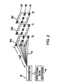
- Fig 2 provides an illustration of the operation of the radiometer 12 in conjunction with the directional scan mechanism 16.
- the scan mechanism 16 directs the radiometer 12 so as to receive radiation 14 from what in effect are 3 x 3 arrays 34a, 34b and 34c of points in the atmosphere ahead of the aircraft collecting sterance associated with an effective range R eff at time intervals t 0 , t 1 and t 2 .
- a middle row 36 of the arrays 34a-c is located at the aircraft's flight level while an upper row 38 is located at a level intermediate between the flight level and an upper flight level and a lower row 40 is located at a level intermediate between the flight level and a lower flight level.
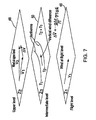
- An illustration of the flight levels is provided in Fig. 7.
- the radiometer 12 can be any suitable commercially available radiometer or a radiometer of the type described in the above referenced patents such as U.S. Patent No. 4,937,447 to Barrett. In another preferred embodiment, only one horizontal temperature map at one level is used for determining wind difference
- the temperature conversion 18 of each point in the arrays 34a-c is accomplished by translating the radiance L( ⁇ ) received by the radiometer 12, where the wavelength is ⁇ , into a signal that is associated with a temperature T eff of the volume of air seen by the radiometer.
- the temperature, T eff is associated with the effective range, R eff which is the weighted average distance of the signal reaching the radiometer 12.
- R eff is only useful in conditions for which R eff does not vary significantly during aircraft flight across reasonable distances at a fixed altitude. It has been found that R eff does not vary significantly for normal flight conditions, i.e., R eff is determined by only the wavelength ⁇ , the altitude and latitude of the aircraft and the particular time of year.
- the FASCODE program is a computer model of atmospheric transmission and radiance in the infrared. This program is described and identified in the aforementioned Barrett, U.S. Patent No. 4,937,447.
- Table 1 is a table illustrating the FASCODE (using the mid-latitude, winter atmosphere program) computed effective range R eff vs. ⁇ in the case that ⁇ falls within the preferred band of wavelengths of CO 2 emission for a zenith angle of 90 degrees and an altitude of 35,000 ft. (10'668m).
- the wavelength 12.2 ⁇ m of CO 2 is particularly effective at measuring T eff associated with a range R eff of approximately 120 km for one altitude and latitude. It should be noted that one of the advantages of the invention is that it makes use of previously computed values of R eff so that it is possible to provide accurate maps of atmospheric temperature. Also it is possible to store tables of R eff vs. Altitude and ⁇ vs. R eff such as shown in the Table I above in order to adjust the sensitivity of the system and the effective range for various conditions. Alternatively, it is possible to use more than one wavelength ⁇ to measure more than one T eff at corresponding ranges R eff from the aircraft.
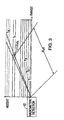
- the radiance L( ⁇ ) detected by the radiometer 12 is a function of the temperature of the naturally occurring CO 2 in the atmosphere. It is possible to associate the temperature of the air in ⁇ V vol shown in Fig. 3 with a given signal.
- the total signal, L( ⁇ ), is the sum of the contributions, L( ⁇ ), of signal from each volume element i along the line of sight of the radiometer 12.
- S 1 is the radiance intercepted by the detector from a volume element i
- ⁇ i is the transmission of the radiance between the volume element i and the detector.
- the temperature T eff is associated with L( ⁇ ), where T eff is the temperature of a blackbody source which produces the same radiometer signal as L( ⁇ ).
- the effective distance R eff is defined according to the equation As indicated at 18 of Fig. 1, the temperature T eff is associated with R eff and a map is generated at 20 with the temperature T eff at a distance R eff in the appropriate direction from the aircraft.
- R eff does not vary significantly and is determined only by altitude and latitude for a given time of year
- the altitude of ⁇ V vol for a R eff of 120 km will be about 1000 ft. above the flight level of the aircraft due to the earth's curvature assuming the radiometer 12 is directed toward the horizon.
- Figs. 4-6 illustrate how the temperature mapping 20 can be accomplished
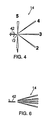
- an aircraft 42 having the radiometer 12 mounted in its nose causes the radiometer 12 to perform an azimuth scan of 180°.
- the radiometer 12 will detect the radiance 14. In this manner a horizontal temperature map is generated.
- the radiometer can detect signals sufficiently fast that the motion of the aircraft can be ignored.
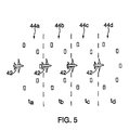
- Fig. 5 shows a series of locations indicated by a set of rectangular boxes 44 a-d that correspond to a set of time intervals t a-d as the aircraft 42 proceeds along its flight path, where the temperatures T eff detected for each location 44 a-d can be stored in memory.
- the radiometer 12 in the aircraft 42 can perform a vertical scan so that temperatures of locations above and below the flight path can be mapped. As a result, it is possible to generate temperature maps for horizontal planes above and below the aircraft 42.
- one of the salient features of the invention is the capability of utilizing the temperature gradients computed at 22 to generate values representing vertical wind vector difference or horizontal winds at various flight levels. In this case, only a horizontal mapping at one level is needed.
- a method according to the invention whereby the thermal . wind concepts can be used to compute vertical wind vector difference, ⁇ V , as indicated at 24 of Fig.
- Equation 3 may be found in any standard meteorological text such as Dynamical and Physical Meteorology by G. J. Haltiner and F. L. Martin, (McGraw-Hill, New York, 1957) p. 204.
- the value of ⁇ V can be computed at 24 for the upper flight level 48 per equation (3).
- V ac the vector dot product, ⁇ V ⁇ V ac , is the increase in headwind or tailwind the aircraft would experience at the different altitude.
- the vector value ⁇ V can then be added to the vector value V 1 of the wind at the current flight level 46 to obtain a vector value V 2 which represents the direction and speed of the wind at the upper flight level 48. This value then can also be displayed on the display 26 in order to provide the air crew with information as to the wind at the upper flight level 48.
- the display 26 can be used to display just the difference in wind speed along the direction of the aircraft's flight at the upper flight level 48, for example by displaying a simple plus or minus sign along with a value representing the difference in velocity.
- the value of V 2 can be used as an input to the flight management system 28 so that factor can be used by the system 28 in determining the most efficient flight regime. Note that the temperatures are only needed in one horizontal plane to determine ⁇ T , and the wind difference, ⁇ V
- Another feature of the invention relates to the use of the temperature mapping function 20 along with the computation of vertical temperature gradients 22 to compute the probability of clear air turbulence 30.
- the vertical temperature mapping 20 can be used to calculate the lapse rate ⁇ T/ ⁇ z for determination of the Richardson number Ri which is correlated with turbulent conditions.
- the Richardson number, Ri is a measure of the probability of CAT. For Ri below 0.21, atmospheric turbulence occurs and CAT is likely. Severity of CAT increases with decreasing Ri. Referring again to Fig. 1, the probability of clear air turbulence is determined at 30 with the result displayed on the CAT display 32.
- Fig. 1 has been described in terms of its use in connection with an aircraft traversing temperature fields in its flight path
- this type of apparatus can also adapted for use in mapping temperature fields from a fixed geographical position.
- the radiometer 12 at a fixed site to scan temperature at the effective range R eff as described above over a period of time as the weather moves over the radiometer, it is possible to generate a map of the temperature fields for a wide area.
- the temperature map can then be used for warnings of wind conditions such as clear air turbulence and dry microburst conditions.
- Another use at a fixed position is to scan the temperature field in 360° azimuth and in elevation to determine wind differences, or CAT at one time.
Landscapes
- Environmental & Geological Engineering (AREA)
- General Physics & Mathematics (AREA)
- Physics & Mathematics (AREA)
- Engineering & Computer Science (AREA)
- Ecology (AREA)
- Remote Sensing (AREA)
- Radar, Positioning & Navigation (AREA)
- Atmospheric Sciences (AREA)
- Spectroscopy & Molecular Physics (AREA)
- Biodiversity & Conservation Biology (AREA)
- Life Sciences & Earth Sciences (AREA)
- Environmental Sciences (AREA)
- Radiation Pyrometers (AREA)
- Indicating Or Recording The Presence, Absence, Or Direction Of Movement (AREA)
- Measuring Temperature Or Quantity Of Heat (AREA)
Description
- The present invention relates generally to an aircraft flight management system, and, an aircraft flight safety system. An apparatus incorporating a passive detector is used for mapping temperature, for detecting the difference in the speed and direction of winds at various altitudes and for predicting clear air turbulence conditions ahead of the aircraft.
- Knowledge of wind speed and direction at various altitudes is valuable to aircraft pilots for numerous reasons. Two reasons include fuel consumption and safety. At cruising altitude an aircraft's fuel consumption could be reduced if the pilot was aware of and took advantage of more favorable wind patterns, such as a lower head wind or a higher tail wind. On long haul flights, the selection of favorable winds would result in significant cost savings to the airline.
- However, currently there are no effective methods or apparatus for passive profiling atmospheric winds ahead of an aircraft during flight. Active systems using Doppler LIDAR are expensive and have limited range. One method for determining fuel-efficient aircraft altitudes is described in Gary, U. S. Patent No 4,474,062. This concept is based on determining the air density at altitudes in the vicinity of the aircraft's present altitude by use of a microwave radiometer to detect the thermal emission from oxygen to indicate the air temperature at a particular altitude. The temperature is then used to determine the air density at that altitude. Since the weight of the aircraft is known during the flight as the fuel is consumed, it is possible to calculate the aircraft weight-to-air density ratio, W/d. This ratio has an optimum value (depending on the type of aircraft) for which the fuel consumption is minimum. The pilot then has the option to change altitude to achieve a more favorable W/d ratio. This method for determining fuel efficient aircraft altitudes is inadequate since it is based only on the determination of the aircraft weight to air density ratio and doesn't take into account the wind speed and direction at the altitude that has the optimum value of W/d. As a result, it may be determined, for example, that the optimum W/d ratio is at an altitude 4000 ft (1219,2 m) above the present aircraft altitude. If the pilot increases his altitude by 4000 ft (1219,2 m) and then finds a significant increase in the head winds, this situation could completely negate any fuel efficiency savings due to having a more optimum W/d ratio.
- In Gary, U.S. Patent No. 4,346,595, it is asserted that by knowing the altitude of the local tropopause, it is possible to find efficient flight altitudes by flying about 2000 ft (609,6 m) above the tropopause when traveling in a westerly direction and about 2000 ft (609,6m) below the tropopause when going in an easterly direction. The tropopause is generally a broad transitional zone between the troposphere and the stratosphere. From an operational standpoint, it is not practical to use the tropopause as a reference from which to make altitude changes. In addition, the system described in Gary does not take into account local variation in winds that may be present at the new altitudes.
- Clear air turbulence (CAT) is a major safety concern for large commercial aircraft. CAT is a weather phenomenon that is due to vertical wind shear in the atmosphere. It usually occurs in temperature inversion layers typically found in the tropopause. CAT results in a rapidly changing airflow over the lift surfaces of the aircraft. Should the forward velocity of the air over the lift surfaces suddenly decrease, the lift will decrease. In this situation, the aircraft may experience a forced descent due to the down flowing air mass and also by an apparent loss in forward air speed. It is thus desirable that an onboard weather system be capable of providing an advanced warning of such wind conditions.
- Since the conditions that result in clear air turbulence are not visually apparent nor are they generally detectable by active sensors such as radar, there have been a number of attempts to detect wind shear and clear air turbulence conditions by passive detectors In particular, attempts have been made to sense air temperature gradients, which are associated with air turbulence, by detecting the radiation emanating from the atmosphere ahead of the aircraft in the infrared and microwave spectral regions. The intensity of the detected radiation varies with the atmospheric temperatures along the line of sight of the detector Typically these passive systems use a radiometer to measure the thermal radiation from one of the atmospheric gases such as carbon dioxide (CO2), oxygen (O2) or water vapor (H2O) to determine changes in the spatial temperature profile in front of the aircraft. Examples of such approaches based on the infrared emission of CO2 are provided in U.S. Patent Nos. 3,475,963, 3,735,136, 3,780,293, 3,935,460, 4,266,130, 4,427,306, 4,937,447, 4,965,572, 4,965,573, 5,105,191, 5,276,326 and 5,285,070. Other approaches determine atmospheric temperature by measuring the microwave emission from O2 as described in U.S. Patent Nos. 3,359,557, 3,380,055, 4,346,595, and 5,117,689 Systems for measuring atmospheric temperature based on infrared emission from H2O are described in U.S. Patent No 4,266.130 and in the paper by Kuhn et al, "Clear Air Turbulence: Detection by Infrared Observations of Water Vapor" in Science. Vol. 196, p.1099, (1977). In addition, there have been several papers written describing these types of passive infrared systems including: S. M. Norman and N. H. Macoy, "Remote Detection of Clear Air Turbulence by Means of an Airborne Infrared System" AJAA Paper No 65-459 presented at the AIAA Second Annual Meeting, San Francisco, CA, July 26-29, 1965; and R. W. Astheimer, "The Remote Detection of Clear Air Turbulence by Infrared Radiation" in Applied Optics Vol 9, No. 8, p.1789 (1970). In U.S. Patent No. 4,346,595, Gary describes a microwave radiometer for determining air temperatures in the atmosphere at ranges of about 3 km from the aircraft for the purpose of detecting the height of the tropopause and the presence of temperature inversions. He teaches that by flying the aircraft above or below the tropopause or temperature inversion layer, it is possible to avoid CAT. Since the effective range of the microwave radiometer is relatively short, the system doesn't provide sufficient warning time for the aircraft to avoid the CAT condition. The present invention has detection ranges on the order of 100 km which will allow time for the aircraft to change altitude to avoid CAT
- A number of the above systems were not successful or were only partially successful because they were based solely on the measurement of atmospheric temperature in order to predict the presence of turbulence. A more reliable indication of atmospheric turbulence can be realized by determining the Richardson number, Ri The use of the Richardson number to determine the stability of the atmosphere is well known in meteorology (see, for example, D. Djuric, Weather Analysis, Prentice Hall, Engiewood Cliffs, NJ, 1994, p. 64). In the present invention, the Richardson number is used to indicate the probability of CAT. In U.S. Patent No. 5,117,689, Gary discussed the correlation of the reciprocal of the Richardson number with the occurrence of CAT conditions The Richardson number, Ri, contains two components: (1) the vertical lapse rate of potential temperature and (2) the wind shear which is related to the horizontal temperature gradient. A number of the prior art discussions measure the vertical temperature lapse rate. Gary used the inertial navigation system (INS) to measure the East-West and North-South components of the wind (the wind shear) along with a microwave radiometer to measure the air temperature vertical lapse rate. This information is then used to calculate the Richardson number or its reciprocal The deficiency of the system described in this patent (U.S. Patent No. 5,117,689) is that it determines the Richardson number at relatively close ranges (less than 3 km) and therefore does not provide advance warning of the CAT condition and that it measures the wind shear only at the aircraft
- Previous approaches for the determination of the range and probability of CAT can be summarized as follows:
- U. S. Patent No. 5,276,326 to Philpott determines turbulence as a function of temperature vs. range through the analysis of infrared radiometer signals at two or more discrete wavelengths. The temperature associated with a given range as a function of wavelength is then derived through a matrix inversion process. This transition is difficult and requires noise and error free input data to yield valid results. The present invention overcomes this difficulty by using only one wavelength. Gary overcomes the multiple wavelength difficulty in Patent No. 4,346,595 by measuring effective temperature and range at a single wavelength. however no attempt is made to determine the probability of clear air turbulence using the Richardson number (Ri). In U. S. Patent No. 5,117,689. Gary teaches the significance of the Richardson number in CAT prediction but does not suggest a method to derive Ri directly from radiometric measurements of horizontal and vertical temperature lapse rates obtained by combining azimuth and elevation scanning with the aircraft motion to produce a temperature map.
- It is therefore an object of the invention to provide a method and apparatus for determining both fuel efficient aircraft altitudes and for predicting clear air turbulence.
- Another object of the invention is to provide a system for generating a temperature map using a passive directional detector which can determine, at predetermined time intervals, atmospheric temperatures in an azimuth plane associated with a predefined range from the detector. The temperature map can then be used to calculate temperature gradients that in turn can be used to compute the vertical wind vector difference and to determine the presence of clear air turbulence.
- A further object of the invention is to provide an advisory system using a passive detector on board an aircraft to determine whether the winds at flight levels up to 6,000 ft. (1828,7 m) above or below the aircraft would be more favorable, either through a lower head wind or a higher tail wind, such that changing altitude would result in reduced fuel consumption. The detector can include an infrared radiometer to determine the temperature field from which the thermal wind at the upper and lower flight levels is calculated.
- Yet another object of the invention is to provide an aircraft clear air turbulence warning system that uses a passive detector on board the aircraft to generate signals representing horizontal temperature gradients and vertical temperature profiles that can be used to compute the Richardson number which in turn can be used to generate a warning when the wind shear exceeds a predetermined value.
- According to one aspect of the present invention there is provided apparatus according to
claim 1. - According to a second aspect of the present invention there is provided a method according to claim 9.
-
- Fig. 1 is a functional block diagram of the preferred embodiment of the invention;
- Fig. 2 is pictorial representation of a scanning array illustrating the operation of a radiometer in the invention of Fig. 1 at three time intervals;
- Fig. 3 is a pictorial representation of a section of the atmosphere illustrating the operation of the radiometer of Fig. 1;
- Fig. 4 is a pictorial representation of an aircraft operating the radiometer of Fig. 1 in a horizontal scan mode;
- Fig. 5 is a pictorial representation of an aircraft acquiring a horizontal temperature map according to the invention of Fig. 1;
- Fig. 6 is a pictorial representation of an aircraft operating the radiometer of Fig. 1 in a vertical scan mode; and
- Fig. 7 is a pictorial representation of the determination of the direction and velocity of wind at a level above the flight level of the aircraft according to the invention.
-
- Fig. 1 provides an overview, in the form of a functional block diagram, of the operation of the preferred embodiment of the invention which in this case is an
apparatus 10 for installation in an aircraft to detect wind vector difference and clear air turbulence. Although the preferred embodiment of the invention is described in terms of its application to aircraft, the invention can have other applications some of which are described below. Installed in a forward, and partially sideways, looking location of the aircraft, such as the nose or a leading portion of a wing is apassive detector 12, preferably a radiometer, for receiving infrared radiation from the atmosphere as indicated by a dashedline 14. Also, as indicated by ablock 16, theradiometer 12 is connected to a directional scanning mechanism which permits theradiometer 12 to receive theradiation 14 from different directions in both the azimuth and vertical directions or in only the azimuth direction. - Shown at
block 18, theapparatus 10 will convert the sterance or energy L at a particular wave length λ of theradiation 14 as detected by theradiometer 12 into a value Teff which represents the temperature of the atmosphere at an effective range Reff from the aircraft. The concept of converting theradiation 14 into temperature Teff and the effective range Reff will be described below. - Then, as indicated at a
block 20, the Teff values obtained will be used to create a horizontal or vertical temperature map of atmospheric temperature ahead of the aircraft as illustrated in Figs. 2-7. As the aircraft progresses along its line of flight, the system data is collected as shown in Fig. 2. The apparatus then generates a temperature map as indicated at 20. - The
temperature mapping 20 is used to compute horizontal temperature gradients VT, indicated at ablock 22, between the temperatures T, contained in themap 20 in a horizontal plane. - As represented by a
block 24 and discussed below, the horizontal temperature gradients VT can be used to compute vertical wind vector difference for flight levels ahead as well as above and below the aircraft. - Effective use of the wind vector difference information generated at 24 can be made, as shown at a
block 26, by displaying the wind vector difference at flight levels above or below the aircraft in order to provide the air crew with information as to winds that might be more favorable. Thisinformation 24 can also be used as an input to a flight management system, indicated by ablock 28, so that it can be combined with other flight parameters to provide guidance as to the most efficient flight regime. In addition, thisinformation 24 can be used to compute the probability of clear air turbulence, as indicated by ablock 30 that in turn can be used as an input to a clear air turbulence display or warning system as shown by ablock 32. - The following is a more detailed description of the various elements and concepts of the invention as shown in the block diagram of Fig. 1.
- For example, Fig 2 provides an illustration of the operation of the
radiometer 12 in conjunction with thedirectional scan mechanism 16. In this case thescan mechanism 16 directs theradiometer 12 so as to receiveradiation 14 from what in effect are 3 x 3arrays middle row 36 of thearrays 34a-c is located at the aircraft's flight level while anupper row 38 is located at a level intermediate between the flight level and an upper flight level and alower row 40 is located at a level intermediate between the flight level and a lower flight level. An illustration of the flight levels is provided in Fig. 7. Theradiometer 12 can be any suitable commercially available radiometer or a radiometer of the type described in the above referenced patents such as U.S. Patent No. 4,937,447 to Barrett. In another preferred embodiment, only one horizontal temperature map at one level is used for determining wind difference - Referring also to Fig. 1 and Fig. 3, the
temperature conversion 18 of each point in thearrays 34a-c is accomplished by translating the radiance L(λ) received by theradiometer 12, where the wavelength is λ, into a signal that is associated with a temperature Teff of the volume of air seen by the radiometer. The temperature, Teff, is associated with the effective range, Reff which is the weighted average distance of the signal reaching theradiometer 12. This use of Reff is only useful in conditions for which Reff does not vary significantly during aircraft flight across reasonable distances at a fixed altitude. It has been found that Reff does not vary significantly for normal flight conditions, i.e., Reff is determined by only the wavelength λ, the altitude and latitude of the aircraft and the particular time of year. This has been verified through the use of the FASCODE program. The FASCODE program is a computer model of atmospheric transmission and radiance in the infrared. This program is described and identified in the aforementioned Barrett, U.S. Patent No. 4,937,447. The following Table 1 is a table illustrating the FASCODE (using the mid-latitude, winter atmosphere program) computed effective range Reff vs. λ in the case that λ falls within the preferred band of wavelengths of CO2 emission for a zenith angle of 90 degrees and an altitude of 35,000 ft. (10'668m).Wavelength (µm) Effective Ranee (km) 12.2 121 12.3 106 12.4 98.2 12.5 84.4 12.6 76.6 12.7 918 12.8 105 12.9 106 13.0 89.3 - It has been found that the wavelength 12.2 µm of CO2 is particularly effective at measuring Teff associated with a range Reff of approximately 120 km for one altitude and latitude. It should be noted that one of the advantages of the invention is that it makes use of previously computed values of Reff so that it is possible to provide accurate maps of atmospheric temperature. Also it is possible to store tables of Reff vs. Altitude and λ vs. Reff such as shown in the Table I above in order to adjust the sensitivity of the system and the effective range for various conditions. Alternatively, it is possible to use more than one wavelength λ to measure more than one Teff at corresponding ranges Reff from the aircraft.
- The radiance L(λ) detected by the
radiometer 12 is a function of the temperature of the naturally occurring CO2 in the atmosphere. It is possible to associate the temperature of the air in ΔVvol shown in Fig. 3 with a given signal. The total signal, L(λ), is the sum of the contributions, L(λ), of signal from each volume element i along the line of sight of theradiometer 12. Thuswhere S1 is the radiance intercepted by the detector from a volume element i and τi is the transmission of the radiance between the volume element i and the detector. The temperature Teff is associated with L(λ), where Teff is the temperature of a blackbody source which produces the same radiometer signal as L(λ). The effective distance R eff is defined according to the equation As indicated at 18 of Fig. 1, the temperature Teff is associated with Reff and a map is generated at 20 with the temperature Teff at a distance Reff in the appropriate direction from the aircraft. For normal flight conditions, Reff does not vary significantly and is determined only by altitude and latitude for a given time of year With respect to Fig. 3, the altitude of ΔVvol for a Reff of 120 km will be about 1000 ft. above the flight level of the aircraft due to the earth's curvature assuming the
radiometer 12 is directed toward the horizon. - Figs. 4-6, illustrate how the
temperature mapping 20 can be accomplished In Fig. 4, anaircraft 42 having theradiometer 12 mounted in its nose causes theradiometer 12 to perform an azimuth scan of 180°. At each of the five positions shown in Fig. 4, theradiometer 12 will detect theradiance 14. In this manner a horizontal temperature map is generated. The radiometer can detect signals sufficiently fast that the motion of the aircraft can be ignored. Fig. 5 shows a series of locations indicated by a set of rectangular boxes 44a-d that correspond to a set of time intervals ta-d as theaircraft 42 proceeds along its flight path, where the temperatures Teff detected for each location 44a-d can be stored in memory. Similarly, as illustrated in Fig 6. theradiometer 12 in theaircraft 42 can perform a vertical scan so that temperatures of locations above and below the flight path can be mapped. As a result, it is possible to generate temperature maps for horizontal planes above and below theaircraft 42. - By mapping the temperature fields 20 as described above, it is possible to compute horizontal temperature gradients ▿T as indicated at 22 of Fig. 1 It is also possible, by using the vertical temperature mapping to calculate the temperature lapse rate ∂T/∂z for use in calculation of the Richardson Number for computing the probability of clear air turbulence.
- As illustrated by the representation of Fig. 7, one of the salient features of the invention is the capability of utilizing the temperature gradients computed at 22 to generate values representing vertical wind vector difference or horizontal winds at various flight levels. In this case, only a horizontal mapping at one level is needed. For example, a method according to the invention whereby the thermal . wind concepts can be used to compute vertical wind vector difference, ΔV, as indicated at 24 of Fig. 1, makes use of the following relation:where g is the acceleration due to gravity, Δz is the distance between Z1 and Z2, f is the Coriolis parameter resulting from the earth's rotation, T is the temperature at said flight altitude Z1, ▿T is the vector representing the temperature gradient at the intermediate level Z3 between Z1 and Z2, k is the unit vector parallel to the aircraft's local vertical and the symbol ⊗ represents the vector cross-product operator. In Fig. 7, Z1 denotes the current flight level of the aircraft, Z2 denotes the flight level above the aircraft and Z3 denotes the intermediate level.

Equation 3 may be found in any standard meteorological text such as Dynamical and Physical Meteorology by G. J. Haltiner and F. L. Martin, (McGraw-Hill, New York, 1957) p. 204. - As a result, once the temperature gradients are computed 22 from the
temperature field 20 the value of ΔV can be computed at 24 for theupper flight level 48 per equation (3). For an aircraft direction vector, Vac , the vector dot product, ΔVVac, is the increase in headwind or tailwind the aircraft would experience at the different altitude. In addition, the vector value ΔV can then be added to the vector value V1 of the wind at thecurrent flight level 46 to obtain a vector value V2 which represents the direction and speed of the wind at theupper flight level 48. This value then can also be displayed on thedisplay 26 in order to provide the air crew with information as to the wind at theupper flight level 48. Alternatively, thedisplay 26 can be used to display just the difference in wind speed along the direction of the aircraft's flight at theupper flight level 48, for example by displaying a simple plus or minus sign along with a value representing the difference in velocity. In addition, the value of V2 can be used as an input to theflight management system 28 so that factor can be used by thesystem 28 in determining the most efficient flight regime. Note that the temperatures are only needed in one horizontal plane to determine ▿T, and the wind difference, ΔV - It will be understood that the above discussed method of determining wind direction and velocity V2 at the
upper flight level 48 would also apply to the determination of wind at a lower flight level below thecurrent flight level 46 In this manner, it is possible to provide on thedisplay 26 or to theflight management system 28 an indication of the winds both above and below the aircraft so that the crew can take advantage ofthis information in selecting the most fuel efficient altitude. - Another feature of the invention relates to the use of the
temperature mapping function 20 along with the computation ofvertical temperature gradients 22 to compute the probability ofclear air turbulence 30. In particular, thevertical temperature mapping 20 can be used to calculate the lapse rate ∂T/∂z for determination of the Richardson number Ri which is correlated with turbulent conditions. In this case Ri is computed using the following relations:where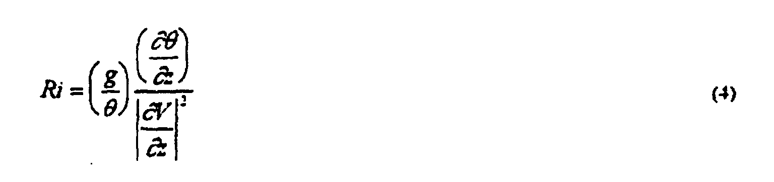
CAT display 32. - The embodiment of the invention in Fig. 1 has been described in terms of its use in connection with an aircraft traversing temperature fields in its flight path However, this type of apparatus can also adapted for use in mapping temperature fields from a fixed geographical position. By using the
radiometer 12 at a fixed site to scan temperature at the effective range Reff as described above over a period of time as the weather moves over the radiometer, it is possible to generate a map of the temperature fields for a wide area. The temperature map can then be used for warnings of wind conditions such as clear air turbulence and dry microburst conditions. Another use at a fixed position is to scan the temperature field in 360° azimuth and in elevation to determine wind differences, or CAT at one time.
Claims (14)
- Apparatus for determining vertical wind vector difference, ΔV, between a first altitude Z1 and a second altitude Z2, said apparatus comprising:a passive radiometer detector (12) for detecting atmospheric temperature Teff at an effective range Reff from different azimuth directions;first computational means (22) for calculating the horizontal temperature gradient, grad T, based on temperature measurements from different azimuth directions; andvertical wind vector difference calculating means (24) for generating a value ΔV/Δz representing the vertical wind vector difference divided by the vertical distance Δz between the first altitude Z1 and the second altitude Z2 utilising the horizontal temperature gradient, grad T, calculated by the first computational means
- Apparatus according to claim 1, wherein the radiometer (12) is mounted to a directional scanning mechanism (16).
- Apparatus according to any of claim 1 or 2 wherein said vertical wind vector difference calculating means (24) calculates the vertical wind vector difference according to the relation
- Apparatus according to claims 1 to 3 in which the passive radiation detector (12) is adapted for detecting atmospheric temperature Teff at an effective range Reff from different vertical directions;
second computational means (22) for calculating the vertical gradient of the potential temperature, δΘ/δz, based on temperature measurements from different vertical directions; and
means for calculating the Richardson Number, Ri, as a function of the vertical gradient of the potential temperature, Θ, and the vertical wind vector difference, ΔV. - Apparatus according to claim 4, wherein said means for calculating the Richardson Number, Ri, is arranged to calculate the Richardson Number, Ri, from the equation
- Apparatus according to claims 4 or 5, further including third computational means (30) for calculating the probability of clear air turbulence from the Richardson Number and display means (32) for displaying said probability of clear air turbulence.
- Apparatus according to any of claims 1 to 6, wherein said apparatus is provided on board of an aircraft.
- Apparatus according to claim 7, wherein said apparatus further includes wind display means (26) for displaying the wind vector difference ΔV at flight levels above and below the aircraft.
- A method for determining vertical wind vector difference, ΔV, between a first altitude Z1 and a second altitude Z2, said method comprising:detecting atmospheric temperature Teff at an effective range Reff from different azimuth directions using a passive radiometer detector (12);calculating the horizontal temperature gradient, grad T, based on temperature measurements from different azimuth directions; andgenerating a value ΔV/Δz representing the vertical wind vector difference divided by the vertical distance Δz between the first altitude Z1 and the second altitude Z2 utilising the horizontal temperature gradient, grad T.
- The method according to claim 9 wherein said vertical wind vector difference is calculated according to the relation
- The method according to claim 9 or 10 further comprising detecting atmospheric temperature Teff at an effective range Reff from different vertical directions;
calculating the vertical gradient of the potential temperature, δΘ/δz, based on temperature measurements from different vertical directions; and
calculating the Richardson Number, Ri, as a function of the vertical gradient of the potential temperature, Θ, and the vertical wind vector difference, ΔV. - The method according to claim 11, wherein the Richardson Number, Ri, is calculated from the equation
- The method according to claim 11 or 12, further including calculating a probability of clear air turbulence from the Richardson Number and displaying the probability of clear air turbulence.
- The method according to anyone of claims 9 to 13, further including displaying the wind vector difference ΔV at flight levels above an below an aircraft.
Priority Applications (2)
| Application Number | Priority Date | Filing Date | Title |
|---|---|---|---|
| EP02003061A EP1221626A3 (en) | 1996-03-08 | 1997-03-06 | Apparatus and method for determining wind profiles and for predicting clear air turbulence |
| EP02003060A EP1221625A3 (en) | 1996-03-08 | 1997-03-06 | Apparatus and method for determining wind profiles and for predicting clear air turbulence |
Applications Claiming Priority (5)
| Application Number | Priority Date | Filing Date | Title |
|---|---|---|---|
| US13312 | 1987-02-11 | ||
| US1331296P | 1996-03-08 | 1996-03-08 | |
| US808589 | 1997-02-28 | ||
| US08/808,589 US6070460A (en) | 1996-03-08 | 1997-02-28 | Apparatus and method for determining wind profiles and for predicting clear air turbulence |
| PCT/US1997/004189 WO1997033187A1 (en) | 1996-03-08 | 1997-03-06 | Apparatus and method for determining wing profiles and for predicting clear air turbulence |
Related Child Applications (2)
| Application Number | Title | Priority Date | Filing Date |
|---|---|---|---|
| EP02003060A Division EP1221625A3 (en) | 1996-03-08 | 1997-03-06 | Apparatus and method for determining wind profiles and for predicting clear air turbulence |
| EP02003061A Division EP1221626A3 (en) | 1996-03-08 | 1997-03-06 | Apparatus and method for determining wind profiles and for predicting clear air turbulence |
Publications (2)
| Publication Number | Publication Date |
|---|---|
| EP0885401A1 EP0885401A1 (en) | 1998-12-23 |
| EP0885401B1 true EP0885401B1 (en) | 2002-11-27 |
Family
ID=26684684
Family Applications (1)
| Application Number | Title | Priority Date | Filing Date |
|---|---|---|---|
| EP97917536A Expired - Lifetime EP0885401B1 (en) | 1996-03-08 | 1997-03-06 | Apparatus and method for determining the vertical wind vector difference |
Country Status (6)
| Country | Link |
|---|---|
| US (2) | US6070460A (en) |
| EP (1) | EP0885401B1 (en) |
| AU (1) | AU2582797A (en) |
| DE (1) | DE69717423T2 (en) |
| MY (1) | MY132546A (en) |
| WO (1) | WO1997033187A1 (en) |
Cited By (1)
| Publication number | Priority date | Publication date | Assignee | Title |
|---|---|---|---|---|
| DE102004034894A1 (en) * | 2004-07-19 | 2006-03-16 | Diehl Bgt Defence Gmbh & Co. Kg | Determination of the wind velocity vector in a fixed terrestrial coordinate system from a flying aircraft, e.g. for determining the wind height profile, using a hot-wire or hot-film anemometer mounted on a moving aircraft |
Families Citing this family (25)
| Publication number | Priority date | Publication date | Assignee | Title |
|---|---|---|---|---|
| US6237405B1 (en) * | 1996-03-08 | 2001-05-29 | Alliedsignal Inc. | Apparatus and method for predicting clear air turbulence |
| US6209821B1 (en) * | 1999-09-14 | 2001-04-03 | The United States Of America As Represented By The Administrator Of The National Aeronautics And Space Administration | Apparatus and method for measuring air temperature ahead of an aircraft for controlling a variable inlet/engine assembly |
| JP3745275B2 (en) * | 2000-04-25 | 2006-02-15 | 三菱電機株式会社 | Airborne turbulence warning system |
| US6505123B1 (en) | 2000-07-24 | 2003-01-07 | Weatherbank, Inc. | Interactive weather advisory system |
| US6828923B2 (en) * | 2002-11-22 | 2004-12-07 | The Boeing Company | Airborne microwave/infrared wind shear and clear air turbulence detector |
| US8902100B1 (en) * | 2008-03-07 | 2014-12-02 | Rockwell Collins, Inc. | System and method for turbulence detection |
| US8708282B2 (en) * | 2004-11-23 | 2014-04-29 | Biosphere Aerospace, Llc | Method and system for loading and unloading cargo assembly onto and from an aircraft |
| US8608110B2 (en) * | 2004-11-23 | 2013-12-17 | Biosphere Aerospace, Llc | Cargo aircraft system |
| US7598901B2 (en) * | 2004-12-03 | 2009-10-06 | The Boeing Company | System for measuring turbulence remotely |
| US20060161469A1 (en) | 2005-01-14 | 2006-07-20 | Weatherbank, Inc. | Interactive advisory system |
| US7400293B2 (en) * | 2006-01-12 | 2008-07-15 | Global Aerospace, Llc | Atmospheric turbulence analysis system |
| US20070162197A1 (en) * | 2006-01-12 | 2007-07-12 | Global Aerospace, Llc | Airplane system for an atmospheric turbulence analysis system |
| US8229467B2 (en) | 2006-01-19 | 2012-07-24 | Locator IP, L.P. | Interactive advisory system |
| US8634814B2 (en) | 2007-02-23 | 2014-01-21 | Locator IP, L.P. | Interactive advisory system for prioritizing content |
| TW200839205A (en) * | 2007-03-16 | 2008-10-01 | Radiant Innovation Inc | Temperature vector gauge |
| FR2914276B1 (en) * | 2007-03-27 | 2009-12-04 | Thales Sa | METHOD AND DEVICE FOR AIRCRAFT PROTECTION AGAINST CLEAR AIR TURBULENCE |
| WO2009002645A2 (en) * | 2007-05-24 | 2008-12-31 | Aviation Communication & Surveillance Systems Llc | Systems and methods for aircraft winshear detection |
| US20090114773A1 (en) * | 2007-11-05 | 2009-05-07 | Helou Jr Elie | Methods for fuel-efficient transportation of cargo by aircraft |
| JP6288665B2 (en) * | 2013-09-12 | 2018-03-07 | 国立研究開発法人宇宙航空研究開発機構 | Landing judgment support system, landing judgment support method, and landing judgment support program |
| US10494108B1 (en) | 2016-05-17 | 2019-12-03 | Rockwell Collins, Inc. | System and method for providing icing condition warnings |
| US11487015B2 (en) * | 2017-06-05 | 2022-11-01 | Bluehalo, Llc | Atmospheric characterization systems and methods |
| US12253649B1 (en) | 2021-08-06 | 2025-03-18 | Bluehalo, Llc | Method and apparatus for measuring optical turbulence using an unmanned aerial vehicle |
| US20230075640A1 (en) * | 2021-09-07 | 2023-03-09 | Nextnav, Llc | Determination of Altitude Uncertainty Including Temperature Lapse Rate |
| US12540891B1 (en) | 2022-01-24 | 2026-02-03 | Bluehalo, Llc | Method and apparatus for measuring extinction using an unmanned aerial vehicle |
| US12523775B2 (en) * | 2023-10-27 | 2026-01-13 | The Boeing Company | Aircraft acceleration prediction using lidar trained artificial intelligence |
Family Cites Families (57)
| Publication number | Priority date | Publication date | Assignee | Title |
|---|---|---|---|---|
| US3427581A (en) * | 1965-08-04 | 1969-02-11 | Litton Systems Inc | Clear air turbulence detector |
| US3465339A (en) * | 1965-10-22 | 1969-09-02 | Collins Radio Co | Method and means for detecting air turbulence |
| US3359557A (en) * | 1966-02-14 | 1967-12-19 | Sperry Rand Corp | Clear air turbulence advance warning and evasive course indicator using radiometer |
| US3448613A (en) * | 1966-09-16 | 1969-06-10 | Jacob Kastner | System for tracking air currents |
| US3404396A (en) * | 1967-01-24 | 1968-10-01 | Boeing Co | Airborne clear air turbulence radar |
| US3491358A (en) * | 1968-02-02 | 1970-01-20 | Us Navy | Atmospheric turbulence detection system |
| US3540829A (en) * | 1968-09-09 | 1970-11-17 | Bell Telephone Labor Inc | Laser detection of clear air turbulence |
| GB1308463A (en) * | 1969-03-06 | 1973-02-21 | Coackley R Reynolds M L | Radiometer apparatus |
| US3646555A (en) * | 1969-05-02 | 1972-02-29 | David Atlas | Method and apparatus for radar turbulence detection |
| US3567915A (en) * | 1969-07-22 | 1971-03-02 | Trw Inc | Method of an apparatus for remotely determining the profile of fluid turbulence |
| BE754792A (en) * | 1969-08-22 | 1971-02-15 | Comp Generale Electricite | SYMMETRICAL DETECTION OF ATMOSPHERIC TURBULENCES |
| US3597283A (en) * | 1969-10-08 | 1971-08-03 | Lubrizol Corp | Phosphating solutions for use on ferrous metal and zinc surfaces |
| US3665467A (en) * | 1969-11-19 | 1972-05-23 | Nasa | Clear air turbulence detector |
| US3599488A (en) * | 1970-03-09 | 1971-08-17 | Canadian Patents Dev | Apparatus for measuring air turbulence encountered by aircraft |
| US3696670A (en) * | 1970-07-09 | 1972-10-10 | Stanford Research Inst | Method and system for detecting clear air turbulence |
| GB1308464A (en) * | 1970-07-10 | 1973-02-21 | Secr Defence | Clear air turbulenc detector apparatus |
| US3715748A (en) * | 1971-04-30 | 1973-02-06 | Us Navy | Method and apparatus for measuring the intensity of atmospheric turbulence |
| US3780293A (en) * | 1972-03-06 | 1973-12-18 | E Flint | Dual beam radiometer for clear air turbulence measurement |
| US3803910A (en) * | 1972-11-06 | 1974-04-16 | G Crompton | Wind turbulence metering |
| US3803601A (en) * | 1973-03-19 | 1974-04-09 | R Serafin | Incoherent turbulence detector |
| US3856402A (en) * | 1973-04-11 | 1974-12-24 | Nasa | Clear air turbulence detector |
| US3935460A (en) * | 1975-02-10 | 1976-01-27 | Flint Edward F | Processing apparatus for clear air turbulence detection |
| US4031756A (en) * | 1976-08-02 | 1977-06-28 | Honeywell Inc. | Ultrasonic air movement and temperature measuring apparatus |
| US4195931A (en) * | 1978-05-18 | 1980-04-01 | The United States Of America As Represented By The Secretary Of The Army | Clear air turbulence detector |
| AU523180B2 (en) * | 1978-08-22 | 1982-07-15 | University Of Melbourne, The | Acoustic detection of wind speed and direction at various altitudes |
| US4266130A (en) * | 1978-10-13 | 1981-05-05 | The United States Of America As Represented By The Secretary Of Commerce | Method and apparatus for detecting clear air turbulences |
| US4303862A (en) * | 1979-07-18 | 1981-12-01 | Geiger Allen R | Clear air turbulence detector |
| US4359640A (en) * | 1979-07-18 | 1982-11-16 | Aero-Geophysical, Inc. | Clear air turbulence detection |
| US4427306A (en) * | 1980-08-04 | 1984-01-24 | University Patents, Inc. | Radiometer apparatus for air disturbance detection |
| US4342912A (en) * | 1980-08-04 | 1982-08-03 | University Patents, Inc. | Apparatus for detecting air disturbances created by low level wind shear |
| US4474062A (en) * | 1981-01-12 | 1984-10-02 | The United States Of America As Represented By The Administrator Of The National Aeronautics And Space Administration | System for indicating fuel-efficient aircraft altitude |
| US4346595A (en) * | 1981-01-12 | 1982-08-31 | Nasa | CAT Altitude avoidance system |
| US4427305A (en) * | 1981-07-13 | 1984-01-24 | Atlantic Richfield Company | Analyzer for distillable materials |
| US4624796A (en) * | 1985-06-07 | 1986-11-25 | Celanese Corporation | Piezoelectric filler and flexible piezoelectric composites |
| US4944891A (en) * | 1985-06-07 | 1990-07-31 | Hoechst Celanese Corp. | Easily poled 0-3 piezoelectric composites for transducer applications |
| US4947165A (en) * | 1987-09-30 | 1990-08-07 | Zweifel Terry L | Windshear detection for aircraft using temperature lapse rate |
| US4965572A (en) * | 1988-06-10 | 1990-10-23 | Turbulence Prediction Systems | Method for producing a warning of the existence of low-level wind shear and aircraftborne system for performing same |
| US4965573A (en) * | 1988-10-03 | 1990-10-23 | Delco Electronics Corporation | Forward looking windshear detection system |
| US4937447A (en) * | 1989-02-24 | 1990-06-26 | Allied-Signal Inc. | Air turbulence detection |
| US5105191A (en) * | 1989-11-13 | 1992-04-14 | Artais Development, Inc. | Apparatus and method for detecting and indicating weather conditions for aircraft |
| EP0525007B1 (en) * | 1990-04-09 | 1997-09-24 | Commonwealth Scientific And Industrial Research Organisation | A detection system for use in an aircraft |
| US5117689A (en) * | 1990-11-27 | 1992-06-02 | The United States Of America As Represented By The Administrator, National Aeronautics And Space Administration | Microwave temperature profiler for clear air turbulence prediction |
| US5218866A (en) * | 1991-02-19 | 1993-06-15 | The United States Of America As Represented By The Secretary Of The Army | Method and device for measuring fluid velocities |
| US5130712A (en) * | 1991-04-09 | 1992-07-14 | Unisys Corporation | Microburst precursor detector utilizing microwave radar |
| US5262782A (en) * | 1991-04-09 | 1993-11-16 | Unisys Corporation | Microburst precursor detector |
| US5311183A (en) * | 1991-06-13 | 1994-05-10 | Westinghouse Electric Corp. | Windshear radar system with upper and lower elevation radar scans |
| US5276326A (en) * | 1991-09-30 | 1994-01-04 | Rockwell International Corporation | Scanning ranging radiometer for weather hazard surveillance |
| US5173704A (en) * | 1991-10-03 | 1992-12-22 | The Boeing Company | Air turbulence detection using bi-static CW Doppler radar |
| NO921193D0 (en) * | 1992-03-26 | 1992-03-26 | Susar As | SYSTEM FOR DETECTION, MEASUREMENT AND CLASSIFICATION OF AIR PHENOMES |
| US5285070A (en) * | 1992-04-02 | 1994-02-08 | Alliedsignal Inc. | Air turbulence detector |
| US5523759A (en) * | 1992-04-14 | 1996-06-04 | Honeywell Inc. | In flight doppler weather radar wind shear detection system |
| US5359888A (en) * | 1993-02-16 | 1994-11-01 | The B. F. Goodrich Company | Air turbulence and wind shear sensor |
| US5639964A (en) * | 1994-10-24 | 1997-06-17 | Djorup; Robert S. | Thermal anemometer airstream turbulent energy detector |
| US5541591A (en) * | 1995-04-21 | 1996-07-30 | Bush; Gary L. | Method and apparatus for measuring and calibration of turbulence |
| US5568151A (en) * | 1995-05-17 | 1996-10-22 | Merritt; David A. | Statistical averaging method for wind profiler doppler spectra |
| US5592171A (en) * | 1995-08-17 | 1997-01-07 | The United States Of America As Represented By The Secretary Of Commerce | Wind profiling radar |
| US5615118A (en) * | 1995-12-11 | 1997-03-25 | Frank; Robert K. | Onboard aircraft flight path optimization system |
-
1997
- 1997-02-28 US US08/808,589 patent/US6070460A/en not_active Expired - Fee Related
- 1997-03-06 EP EP97917536A patent/EP0885401B1/en not_active Expired - Lifetime
- 1997-03-06 WO PCT/US1997/004189 patent/WO1997033187A1/en not_active Ceased
- 1997-03-06 DE DE69717423T patent/DE69717423T2/en not_active Expired - Fee Related
- 1997-03-06 MY MYPI97000937A patent/MY132546A/en unknown
- 1997-03-06 AU AU25827/97A patent/AU2582797A/en not_active Abandoned
-
1998
- 1998-05-22 US US09/083,484 patent/US6000285A/en not_active Expired - Fee Related
Non-Patent Citations (1)
| Title |
|---|
| J.M. WALLACE & P.V. HOBBS: "Atmospheric Science", 1977, ACADEMIC PRESS, ORLANDO * |
Cited By (1)
| Publication number | Priority date | Publication date | Assignee | Title |
|---|---|---|---|---|
| DE102004034894A1 (en) * | 2004-07-19 | 2006-03-16 | Diehl Bgt Defence Gmbh & Co. Kg | Determination of the wind velocity vector in a fixed terrestrial coordinate system from a flying aircraft, e.g. for determining the wind height profile, using a hot-wire or hot-film anemometer mounted on a moving aircraft |
Also Published As
| Publication number | Publication date |
|---|---|
| DE69717423T2 (en) | 2003-08-28 |
| WO1997033187A1 (en) | 1997-09-12 |
| US6070460A (en) | 2000-06-06 |
| DE69717423D1 (en) | 2003-01-09 |
| MY132546A (en) | 2007-10-31 |
| EP0885401A1 (en) | 1998-12-23 |
| US6000285A (en) | 1999-12-14 |
| AU2582797A (en) | 1997-09-22 |
Similar Documents
| Publication | Publication Date | Title |
|---|---|---|
| US6000285A (en) | Apparatus and method for determining wind profiles and for predicting clear air turbulence | |
| US6184816B1 (en) | Apparatus and method for determining wind profiles and for predicting clear air turbulence | |
| US6563452B1 (en) | Apparatus and method for determining wind profiles and for predicting clear air turbulence | |
| US6456226B1 (en) | Nowcast of conviction-induced turbulence using information from airborne radar | |
| US6237405B1 (en) | Apparatus and method for predicting clear air turbulence | |
| US9612328B1 (en) | Weather radar system and method for estimating vertically integrated liquid content | |
| US5615118A (en) | Onboard aircraft flight path optimization system | |
| US4346595A (en) | CAT Altitude avoidance system | |
| US7664601B2 (en) | Weather incident prediction | |
| US5974875A (en) | Apparatus and method for predicting clear air turbulence | |
| US5117359A (en) | System and method for detection of microbursts by measuring various weather condition parameters at both spaced time and location intervals | |
| EP3070501A1 (en) | Prediction of ice crystal presence in a volume of airspace | |
| US8547225B2 (en) | Systems and methods for remote detection of volcanic plumes using satellite signals | |
| Yueh et al. | QuikSCAT wind retrievals for tropical cyclones | |
| US4965572A (en) | Method for producing a warning of the existence of low-level wind shear and aircraftborne system for performing same | |
| Eloranta et al. | Volume‐imaging lidar observations of the convective structure surrounding the flight path of a flux‐measuring aircraft | |
| US5276326A (en) | Scanning ranging radiometer for weather hazard surveillance | |
| EP1221626A2 (en) | Apparatus and method for determining wind profiles and for predicting clear air turbulence | |
| Marlton | On the development, characterisation and applications of a balloon-borne atmospheric turbulence sensor | |
| EP1228383A1 (en) | Weather incident prediction | |
| Wakefield et al. | Design and execution of the marine stratocumulus experiment | |
| Chan et al. | Aviation Applications of the Pulsed Doppler LIDAR- Experience in Hong Kong | |
| John | Field tests of a sonic anemometer-thermometer | |
| Weaver et al. | The 1979 clear air turbulence flight test program | |
| Zak et al. | Operational Performance of Sensor Systems Used to Determine Atmospheric Boundary Layer Properties as Part of the NASA Aircraft Vortex Spacing System Project |
Legal Events
| Date | Code | Title | Description |
|---|---|---|---|
| PUAI | Public reference made under article 153(3) epc to a published international application that has entered the european phase |
Free format text: ORIGINAL CODE: 0009012 |
|
| 17P | Request for examination filed |
Effective date: 19980909 |
|
| AK | Designated contracting states |
Kind code of ref document: A1 Designated state(s): CH DE FR GB IT LI |
|
| 17Q | First examination report despatched |
Effective date: 20000814 |
|
| RTI1 | Title (correction) |
Free format text: APPARATUS AND METHOD FOR DETERMINING THE VERTICAL WIND VECTOR DIFFERENCE |
|
| GRAG | Despatch of communication of intention to grant |
Free format text: ORIGINAL CODE: EPIDOS AGRA |
|
| GRAG | Despatch of communication of intention to grant |
Free format text: ORIGINAL CODE: EPIDOS AGRA |
|
| GRAH | Despatch of communication of intention to grant a patent |
Free format text: ORIGINAL CODE: EPIDOS IGRA |
|
| GRAH | Despatch of communication of intention to grant a patent |
Free format text: ORIGINAL CODE: EPIDOS IGRA |
|
| GRAA | (expected) grant |
Free format text: ORIGINAL CODE: 0009210 |
|
| AK | Designated contracting states |
Kind code of ref document: B1 Designated state(s): CH DE FR GB IT LI |
|
| REG | Reference to a national code |
Ref country code: GB Ref legal event code: FG4D |
|
| REG | Reference to a national code |
Ref country code: CH Ref legal event code: EP |
|
| REF | Corresponds to: |
Ref document number: 69717423 Country of ref document: DE Date of ref document: 20030109 |
|
| ET | Fr: translation filed | ||
| PLBE | No opposition filed within time limit |
Free format text: ORIGINAL CODE: 0009261 |
|
| STAA | Information on the status of an ep patent application or granted ep patent |
Free format text: STATUS: NO OPPOSITION FILED WITHIN TIME LIMIT |
|
| 26N | No opposition filed |
Effective date: 20030828 |
|
| PGFP | Annual fee paid to national office [announced via postgrant information from national office to epo] |
Ref country code: CH Payment date: 20050317 Year of fee payment: 9 |
|
| PG25 | Lapsed in a contracting state [announced via postgrant information from national office to epo] |
Ref country code: LI Free format text: LAPSE BECAUSE OF NON-PAYMENT OF DUE FEES Effective date: 20060331 Ref country code: CH Free format text: LAPSE BECAUSE OF NON-PAYMENT OF DUE FEES Effective date: 20060331 |
|
| REG | Reference to a national code |
Ref country code: CH Ref legal event code: PL |
|
| PGFP | Annual fee paid to national office [announced via postgrant information from national office to epo] |
Ref country code: IT Payment date: 20080320 Year of fee payment: 12 Ref country code: GB Payment date: 20080211 Year of fee payment: 12 |
|
| PGFP | Annual fee paid to national office [announced via postgrant information from national office to epo] |
Ref country code: FR Payment date: 20080307 Year of fee payment: 12 Ref country code: DE Payment date: 20080331 Year of fee payment: 12 |
|
| GBPC | Gb: european patent ceased through non-payment of renewal fee |
Effective date: 20090306 |
|
| REG | Reference to a national code |
Ref country code: FR Ref legal event code: ST Effective date: 20091130 |
|
| PG25 | Lapsed in a contracting state [announced via postgrant information from national office to epo] |
Ref country code: DE Free format text: LAPSE BECAUSE OF NON-PAYMENT OF DUE FEES Effective date: 20091001 |
|
| PG25 | Lapsed in a contracting state [announced via postgrant information from national office to epo] |
Ref country code: GB Free format text: LAPSE BECAUSE OF NON-PAYMENT OF DUE FEES Effective date: 20090306 Ref country code: FR Free format text: LAPSE BECAUSE OF NON-PAYMENT OF DUE FEES Effective date: 20091123 |
|
| PG25 | Lapsed in a contracting state [announced via postgrant information from national office to epo] |
Ref country code: IT Free format text: LAPSE BECAUSE OF NON-PAYMENT OF DUE FEES Effective date: 20090306 |
|
| P01 | Opt-out of the competence of the unified patent court (upc) registered |
Effective date: 20230525 |