EP0884785A2 - Trench capacitor dram cell with vertical transistor - Google Patents
Trench capacitor dram cell with vertical transistor Download PDFInfo
- Publication number
- EP0884785A2 EP0884785A2 EP98109684A EP98109684A EP0884785A2 EP 0884785 A2 EP0884785 A2 EP 0884785A2 EP 98109684 A EP98109684 A EP 98109684A EP 98109684 A EP98109684 A EP 98109684A EP 0884785 A2 EP0884785 A2 EP 0884785A2
- Authority
- EP
- European Patent Office
- Prior art keywords
- layer
- trench
- substrate
- gate
- trench capacitor
- Prior art date
- Legal status (The legal status is an assumption and is not a legal conclusion. Google has not performed a legal analysis and makes no representation as to the accuracy of the status listed.)
- Granted
Links
Images


Classifications
-
- H—ELECTRICITY
- H10—SEMICONDUCTOR DEVICES; ELECTRIC SOLID-STATE DEVICES NOT OTHERWISE PROVIDED FOR
- H10B—ELECTRONIC MEMORY DEVICES
- H10B12/00—Dynamic random access memory [DRAM] devices
- H10B12/30—DRAM devices comprising one-transistor - one-capacitor [1T-1C] memory cells
- H10B12/39—DRAM devices comprising one-transistor - one-capacitor [1T-1C] memory cells the capacitor and the transistor being in a same trench
- H10B12/395—DRAM devices comprising one-transistor - one-capacitor [1T-1C] memory cells the capacitor and the transistor being in a same trench the transistor being vertical
-
- H—ELECTRICITY
- H01—ELECTRIC ELEMENTS
- H01L—SEMICONDUCTOR DEVICES NOT COVERED BY CLASS H10
- H01L21/00—Processes or apparatus adapted for the manufacture or treatment of semiconductor or solid state devices or of parts thereof
- H01L21/02—Manufacture or treatment of semiconductor devices or of parts thereof
- H01L21/04—Manufacture or treatment of semiconductor devices or of parts thereof the devices having at least one potential-jump barrier or surface barrier, e.g. PN junction, depletion layer or carrier concentration layer
- H01L21/18—Manufacture or treatment of semiconductor devices or of parts thereof the devices having at least one potential-jump barrier or surface barrier, e.g. PN junction, depletion layer or carrier concentration layer the devices having semiconductor bodies comprising elements of Group IV of the Periodic System or AIIIBV compounds with or without impurities, e.g. doping materials
-
- H—ELECTRICITY
- H10—SEMICONDUCTOR DEVICES; ELECTRIC SOLID-STATE DEVICES NOT OTHERWISE PROVIDED FOR
- H10B—ELECTRONIC MEMORY DEVICES
- H10B12/00—Dynamic random access memory [DRAM] devices
- H10B12/01—Manufacture or treatment
- H10B12/02—Manufacture or treatment for one transistor one-capacitor [1T-1C] memory cells
- H10B12/03—Making the capacitor or connections thereto
- H10B12/038—Making the capacitor or connections thereto the capacitor being in a trench in the substrate
- H10B12/0383—Making the capacitor or connections thereto the capacitor being in a trench in the substrate wherein the transistor is vertical
Definitions
- the invention generally relates to devices and device fabrication and, more particularly, vertical transistor.
- insulating, semiconducting, and conducting layers are formed on a substrate.
- the layers are patterned to create features and spaces.
- the minimum dimension or feature size (F) of the features and spaces depends on the resolution capability of the lithographic systems.
- the features and spaces are patterned so as to form devices, such as transistors, capacitors, and resistors. These devices are then interconnected to achieve a desired electrical function.
- the formation and patterning of the various device layers are achieved using conventional fabrication techniques, such as oxidation, implantation, deposition, epitaxial growth of silicon, lithography, and etching. Such techniques are described in S.M. Sze, VLSI Technology , 2nd ed., New York, McGraw-Hill, 1988, which is herein incorporated by reference for all purposes.
- Random access memories such as dynamic random access memories (DRAMs) comprise memory cells that are configured in rows and columns to provide storage of information.
- One type of memory cell includes a transistor connected to, for example, a trench capacitor by a strap.
- the capacitor is referred to as a "node”. When activated, the transistor allows data to be read or written into the capacitor.
- the invention relates to a vertical transistor.
- the vertical transistor is incorporated in a memory cell having a trench capacitor.
- the trench capacitor is formed in a substrate, such as a silicon wafer.
- the top surface of the trench capacitor is recessed below a top surface of the substrate.
- a shallow trench isolation (STI) is provided to isolate the memory cell from other devices.
- the STI overlaps a portion of the trench capacitor, leaving a remaining portion above the trench capacitor.
- a transistor is located on the substrate opposite the STI.
- the transistor comprises a gate, drain, and source.
- the gate includes a conductive layer having a horizontal portion located above the surface of the substrate and a vertical portion wrapping into the remaining portion between the silicon sidewall and STI sidewall.
- the vertical portion of the transistor is isolated from the trench capacitor by a dielectric layer.
- the present invention relates a vertical transistor.
- the present invention is described in the context of fabricating a trench capacitor DRAM cell.
- the invention is significantly broader and extends to the fabrication of transistors in general.
- a description a conventional trench capacitor DRAM cell is provided.
- a conventional trench capacitor DRAM cell 100 is shown.
- Such conventional trench capacitor DRAM cell is described in, for example, Nesbit et al., A 0.6 ⁇ m 2 256Mb Trench DRAM Cell With Self-Aligned Buried Strap (BEST) , IEDM 93-627, which is herein incorporated by reference for all purposes.
- BEST Self-Aligned Buried Strap
- IEDM 93-627 which is herein incorporated by reference for all purposes.
- an array of cells are interconnected by wordlines and bitlines to form a DRAM chip.
- the DRAM cell comprises a trench capacitor 160 formed in a substrate 101.
- the substrate is lightly doped with p-type dopants (p - ), such as boron (B).
- the trench is filled with, typically, polysilicon (poly) 161 heavily doped with n-dopants (n + ), such as arsenic (As).
- p - p-type dopants
- n + n-dopants
- As arsenic
- the poly serves as one plate of the capacitor.
- the other plate of the capacitor is formed by a buried plate 165 doped with As.
- the DRAM cell also comprises a horizontal transistor 110.
- the transistor includes a gate 112, source 113, and drain 114.
- the gate and source are formed by implanting n-type dopants, such as phosphorus (P). Connection of the transistor to the capacitor is achieved via a strap 125.
- the strap is formed by providing As dopants outdiffused from the As doped poly in the trench.
- a collar 168 is formed at the top portion of the trench.
- the collar prevents punchthrough of the node junction to the buried plate. Punchthrough is undesirable as it affects the operability of the cell. As shown, the collar defines the bottom of the buried strap and the top of the buried plate.
- the peak concentration of dopants in the buried n-well is at about the bottom of the collar.
- the well is lightly doped.
- the buried well serves to connect the buried plates of the DRAM cells in the array
- Activation of the transistor by providing the appropriate voltages at the source and gate enables data to be written or read from the trench capacitor.
- the gate and source form a wordline and a bitline, respectively, in the DRAM array.
- a shallow trench isolation (STI) 180 is provided to isolate the DRAM cell from other cells or devices.
- a wordline 120 is formed over the trench and isolated therefrom by the STI.
- Wordline 120 is referred to as the "passing wordline”.
- Such configuration is referred to as a folded bitline architecture.
- Fig. 2 shows an exemplary embodiment of a vertical transistor 250 in accordance with the invention.
- the vertical transistor is implemented in a DRAM cell 201.
- the DRAM cell is a merged isolation node trench (MINT) cell.
- MINT merged isolation node trench
- the DRAM cell employs a trench capacitor 210 formed in a substrate 203.
- the substrate for example, is lightly doped with dopants having a first conductivity.
- the substrate is lightly doped with p-type dopants (p - ), such as B.
- the trench comprises poly 211 heavily doped with dopants having a second conductivity.
- the poly is heavily doped with n-type dopants (n + ) such as, for example, As or P.
- the poly is heavily doped with As.
- the poly 211 serves as one plate of the capacitor.
- the other plate of the capacitor is formed by a n-type buried plate 220 comprising, for example, As.
- a collar 227 is provided near the top of the trench and extends slightly below the top of the buried plate.
- the collar is sufficiently thick to prevent punchthrough from the node junction to the buried plate.
- the collar is about 30-40 nm.
- a n-type buried well 225 comprising, for example, P dopants is provided at about the bottom of the collar 227. The buried well connects the buried plates of the other DRAM cells in the array together.
- the vertical transistor 250 is a n-channel transistor.
- the transistor comprises a gate stack 256, source 251, and drain 252.
- the gate stack also referred to as the "wordline”, typically includes conductive 253 and nitride 255 layers.
- the conductive layer 253, in one embodiment, is a poly layer.
- the conductive layer is a polycide layer to reduce the resistance of the wordline.
- the polycide layer comprises a silicide layer on top of a poly layer.
- silicides including molybdenum (MoSi x ), tantalum (TaSi x ), tungsten (WSi x ), titanium (TiSi x ) or cobalt (CoSi x ) are useful to form the silicide layer.
- Aluminum or refractory metals, such as tungsten and molybdenum, may also be used alone or in combination with silicides to form the conductive layer.
- a portion 245 of the gate comprising poly extends beyond the edge of the gate stack 256 and into the upper portion of the trench.
- a dielectric layer 233 located below the portion 245 of the gate is provided.
- the dielectric layer is sufficiently thick to isolate portion 245 from the node.
- the isolation layer comprises a dielectric material such as oxide formed by, for example, high density plasma deposition.
- the gate Underneath the gate is a gate oxide 259.
- the gate oxide extends from underneath the gate stack 256 to the opposite side of the source 251 and wraps around the sidewall of the substrate, extending towards the isolation layer 233.
- the drain is located in the silicon substrate adjacent to the wrap around portion of the gate oxide.
- the drain and source comprise appropriate dopant profiles to achieve the desired electrical characteristics.
- the gate comprises a horizontal portion 256 and a vertical portion 245.
- the length of the device can be extended without increasing surface area. For example, the length of the device can be increased by forming the vertical portion deeper into the substrate. Therefore, the vertical transistor avoids the problems associated with short channel effect.
- the dielectric layer 233 is separated from the collar.
- the separation is large enough to allow sufficient current to flow from the node to the drain, thus providing the connection between the transistor and the capacitor.
- the drain is formed by outdiffusing As from the trench poly.
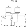
- a STI 380 is provided.
- a top surface 381 of the STI is raised above the plane of the silicon substrate surface 390.
- a non-raised STI is also useful.
- Raised STI Raised STI (RSTI) is described in copending US application titled Reduced Oxidation Stress In The Fabrication Of Devices (attorney docket number 97 P 7487 US) and is herein incorporated by reference for all purposes.
- the top surface of the RSTI is raised above the substrate surface sufficiently to effectively reduce the formation of divots extending below the silicon substrate surface. Formation of divots below the silicon substrate surface adversely affects the operability of the DRAM cells in the array.
- the distance that the top surface of the RSTI is raised is ⁇ about 100 nm.
- the distance is about 20 - 100 nm, more preferably about 40 - 80 nm, and even more preferably about 50 - 70 nm.
- the distance that the top surface of the RSTI is raised is about 50 nm.
- a STI having a top surface substantially planar with the surface of the silicon substrate is also useful.
- a thin layer of oxide 240 is provided above the RSTI.
- the oxide extends into a portion of the poly 213 of the gate stack.
- the oxide serves as an etch stop for the etch that forms the gate stack.
- the oxide extends into the gate stack sufficiently to prevent gate stack etch from etching into portion 245 of the gate. In one embodiment, the oxide extends nominally about 1/3 the width of the gate.
- a passing wordline (not shown) is formed above the RSTI.
- the passing wordline is isolated from the trench by the RSTI.
- one edge of the passing wordline is aligned with the trench sidewall that is opposite of the sidewall with which the gate 256 is aligned and extends away from gate 256.
- Such configuration is referred to as an open-folded bitline architecture.
- Other configuration such as, for example, folded or open architecture is also useful.
- the first conductivity is p-type and the second conductivity is n-type.
- forming the DRAM cell in a n-type substrate with p-type poly filled trench is also useful. Further, it is possible to heavily or lightly doped the substrate, wells, buried plate, and other elements of the DRAM cell with impurity atoms to achieve the desired electrical characteristics
- Figs. 3a-g show the process for forming the vertical transistor implemented in a DRAM cell comprising a trench transistor and a RSTI.
- a trench capacitor 410 is formed in a substrate 301.
- the major surface of the substrate is not critical and any suitable orientation such as a (100), (110), or (111) is useful.
- the substrate is a silicon wafer that has been lightly doped with p-type dopants (p - ), such as B.
- p - ), such as B p-type dopants
- a pad stack 330 is formed on the surface of the substrate.
- the pad stack comprises, for example, a pad oxide layer 331, a polish stop layer 332, and a hard mask layer (not shown).
- the polish stop layer comprises, for example, nitride and the hard mask comprises TEOS.
- Other material, such as BPSG, BSG, or SAUSG is also useful for the hard mask layer.
- the trench capacitor 310 is formed in the substrate by conventional techniques. Such techniques are described in, for example, Müller et al., Trench Storage Node Technology for Gigabit DRAM Generations , IEDM 96-507, which is already herein incorporated by reference for all purposes.
- the trench is filled with poly 314 that has been heavily doped with As dopants.
- the doped poly serves as one plate of the capacitor.
- a buried plate 320 comprising of As dopants surrounds the bottom portion of the trench and serves as the other plate of the capacitor.
- the trench and buried plate are isolated from each other by a node dielectric layer 312.
- the node dielectric layer comprises nitride and oxide layers.
- a collar 327 is formed in an upper portion of the trench.
- the collar comprises a dielectric material such as, for example, TEOS.
- a n-type well 325 lightly doped with P dopants is provided for interconnecting the buried plates of the DRAM cells in the array together.
- the surface of the substrate have been polished by, for example, chemical mechanical polishing (CMP).
- CMP chemical mechanical polishing
- the nitride layer 332 serves as a CMP stop layer, causing the CMP to stop once it reaches the nitride layer.
- the poly that covers the surface of the substrate is removed, leaving a substantially planar surface between the nitride layer 332 and trench poly 314 for subsequent processing.
- the doped poly 314 in the trench is recessed, by for example, reactive ion etching (RIE) to a depth sufficient to accommodate the length of the vertical transistor.
- RIE reactive ion etching
- the poly is recessed to about 200-500 nm below the silicon surface.
- the poly is recessed to about 300-400 nm below the silicon surface, more preferably to about 350 nm.
- the sidewalls of the trench are cleaned for subsequent processes. Cleaning the sidewalls also recesses the collar below a top surface 315 of the doped poly 314. This results in a gap between the silicon and poly sidewalls.
- a poly layer is deposited on the substrate, covering the nitride layer 330 and top portion of the trench.
- the poly layer is an intrinsic or undoped poly layer.
- the poly layer is planarized down to the nitride layer 232. After planarization, the poly in the trench is recessed to, for example, about 300 nm below the surface of the substrate, leaving a strap 340 of about 50 nm thick above the doped poly 314.
- a dielectric layer such as oxide is formed over the surface of the substrate.
- the oxide layer is, for example, a nonconformal layer formed by high density chemical vapor deposition (HDCVD).
- An etch is performed to partially remove the oxide so as to leave an oxide layer 341 over the strap 340.
- the oxide layer is sufficiently thick to isolate the gate of the transistor that is to be formed in the upper portion of the trench above. In one embodiment, the oxide layer is about 50 nm thick.
- the pad nitride and oxide layers are then removed.
- the pad nitride layer is removed by, for example, wet chemical etch.
- the wet chemical etch is selective to oxide.
- an overetch is employed.
- the pad oxide is removed by wet chemical etch selective to silicon. Since the oxide layer 341 is thicker than the pad oxide, it has a lower etch rate. As a result, removal of the pad oxide removes only a defined amount of the oxide layer 341.
- oxide layer is then formed on the surface of the wafer.
- the oxide layer referred to as a "gate sacrificial layer", serves as a screen oxide for subsequent ion implantation
- a resist layer (not shown) is deposited on top of the oxide layer and appropriately patterned to expose the p-type well region.
- P-type dopants such as B
- the dopants are implanted sufficiently deep to prevent punchthrough.
- the dopant profile is tailored to achieve the desired electrical characteristics, such as gate threshold voltage (V t ).
- V t gate threshold voltage
- n-type wells for n-channel support circuitry are also formed.
- CMOS complimentary metal oxide silicon
- n-type wells are formed. Formation of n-type wells requires additional lithographic and implant steps for defining and forming the n-type wells. As with the p-type wells, the profile of the n-type wells are tailored to achieve the desired electrical characteristics.
- the gate sacrificial layer is removed.
- a gate oxidation layer 359 is then formed.
- the various process steps causes As dopants from the doped poly 314 in the trench to diffuse through the strap 340 to form the drain 335.
- the thermal budget of the subsequent processes are taken into account to tailor the dopant profile of the drain.
- a poly layer 354 is deposited over the gate oxide layer 359.
- the poly layer serves as the lower portion of the conductive layer of the gate stack.
- the thickness of the poly layer is about 20 - 70 nm, preferably about 30 nm.
- the poly layer is conformal to the topography of the substrate surface. As such, a hole 370 is created above the trench.
- a dielectric layer is then formed over the poly layer to sufficiently fill the void.
- the dielectric layer comprises, for example, an oxide layer. Nitride is also useful to fill the void. In one embodiment, the dielectric The oxide layer is then removed and polished selective to poly, leaving the void above the trench filled with oxide.
- a nitride layer 372 is formed over the poly layer.
- the nitride layer is sufficiently thick to serve as an polish stop for subsequent processes.
- the thickness of the nitride layer is about 500-1000 ⁇ .
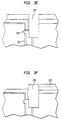
- Fig. 3e shows the process for defining and forming the RSTI region of the DRAM cell.
- the RSTI region overlaps a portion of the trench, leaving a remaining portion to permit a sufficient amount of current to flow between the transistor and capacitor.
- the RSTI overlaps ⁇ about half the trench width, preferably about half the trench width.
- the STI region 330 is achieved with conventional lithographic techniques. After the RSTI region is defined, it is anisotropically etched by, for example, RIE. The RSTI region is etched sufficiently deep to isolate the buried strap 340 from the silicon sidewall opposite the side where the transistor of the DRAM cell is to be formed. As shown, the RSTI region is etched to a depth that is below the top 328 of the collar 327. In one embodiment, the RSTI region is etched about 450 nm below the silicon surface.
- a dielectric material such as, for example, TEOS is deposited on the surface of the substrate to sufficiently fill the RSTI region 330.
- a thin oxide layer is first formed on the surface of the substrate by, for example, rapid thermal oxidation (RTO).
- RTO rapid thermal oxidation
- a thicker layer of oxide, such as TEOS is then deposited over the RTO oxide layer.
- the TEOS is sufficiently thick to fill the RSTI.
- the TEOS for example, is about 5000-6000 ⁇ thick. Forming a thin oxide layer to serve as a seed oxide layer for the thicker TEOS layer reduces stress during the TEOS growth.
- the TEOS layer is conformal, planarization schemes such as, for example, maskless STI are employed.
- the excess TEOS is removed by RIE and polished so that the top surface of the RSTI is planar with the surface of the nitride layer 372.
- the RSTI oxide is densified to improve subsequent wet etch selectivity. Densification of the RSTI oxide is by, for example, annealing.
- the nitride layer is removed. During the removal of the nitride, a portion of the RSTI oxide is also removed, leaving the top surface of the RSTI substantially planar with the top surface of the poly layer 354.
- An oxide layer is then formed over the nitride layer and patterned to form oxide 340.
- the oxide typically is located over the RSTI 330 and extends pass the edge of the trench sidewall on the side where the transistor is formed to serve as an etch stop for the gate stack etch.
- the oxide 340 prevents the gate stack etch from etching into the portion 351 of the poly in the top of the trench. In one embodiment, the oxide 340 extends beyond the trench sidewall a distance that is nominally about 1/3 the width of the gate.
- various layers forming the gate stack are formed over poly 354 and oxide 340.
- a poly layer 355 is formed over the poly layer 354.
- Poly layer 355 is used to form the upper portion of conductive layer in the gate stack.
- a silicide layer comprising, for example, W x Si is formed to produce a composite gate stack to lower the wordline resistance.
- the combined thickness of the layers 353 and 354 are sufficient to formed the conductive layer of the gate. Of course, this thickness may vary depending on design specifications. In one embodiment, the thickness of the combined layers is about 50-100 nm.
- a nitride layer 357 is formed above layer 355. The nitride layer serves as an etch stop for forming a boarderless bitline contact.
- the surface of the substrate is patterned to form a gate stack for a transistor 380 of the DRAM cell.
- a passing gate stack 370 is typically formed over the trench and isolated therefrom by the RSTI.
- Source 381 is formed by implanting or outdiffusing dopants having the appropriate profile to achieve the desired operating characteristics.
- P dopants are implanted to form the source.
- nitride spacers may be employed.
Abstract
Description
Claims (1)
- A random access memory cell comprising:a trench capacitor formed in a substrate, wherein a top surface of the trench capacitor is recessed below a top surface of the substrate;a shallow trench isolation (STI), the STI overlapping a portion of the trench capacitor so as to leave a remaining portion above the trench capacitor, anda transistor located on the substrate opposite the STI, the transistor comprising a gate, drain, and source, the gate comprising a conductive layer having a horizontal portion located above the surface of the substrate and a vertical portion wrapping into the remaining portion below the surface of the substrate and above the trench capacitor,a dielectric layer located above the trench capacitor to isolate the second gate portion from the trench capacitor.
Applications Claiming Priority (2)
| Application Number | Priority Date | Filing Date | Title |
|---|---|---|---|
| US87278097A | 1997-06-11 | 1997-06-11 | |
| US872780 | 1997-06-11 |
Publications (3)
| Publication Number | Publication Date |
|---|---|
| EP0884785A2 true EP0884785A2 (en) | 1998-12-16 |
| EP0884785A3 EP0884785A3 (en) | 2001-10-10 |
| EP0884785B1 EP0884785B1 (en) | 2006-07-12 |
Family
ID=25360277
Family Applications (1)
| Application Number | Title | Priority Date | Filing Date |
|---|---|---|---|
| EP98109684A Expired - Lifetime EP0884785B1 (en) | 1997-06-11 | 1998-05-28 | Trench capacitor dram cell with vertical transistor |
Country Status (6)
| Country | Link |
|---|---|
| EP (1) | EP0884785B1 (en) |
| JP (1) | JPH1117151A (en) |
| KR (1) | KR100481035B1 (en) |
| CN (1) | CN1202012A (en) |
| DE (1) | DE69835184T2 (en) |
| TW (1) | TW425718B (en) |
Cited By (10)
| Publication number | Priority date | Publication date | Assignee | Title |
|---|---|---|---|---|
| EP0948043A2 (en) * | 1998-03-31 | 1999-10-06 | Siemens Aktiengesellschaft | Method with improved controllability of a buried layer |
| EP1017095A2 (en) * | 1998-12-29 | 2000-07-05 | Infineon Technologies North America Corp. | DRAM trench capacitor cell |
| EP1039534A3 (en) * | 1999-03-24 | 2001-04-04 | Infineon Technologies North America Corp. | Dynamic random access memory |
| WO2002001606A2 (en) * | 2000-06-23 | 2002-01-03 | Infineon Technologies North America Corp. | Trench capacitor dram cell layout |
| WO2003001593A2 (en) * | 2001-06-22 | 2003-01-03 | Infineon Technologies Ag | Sti process for dram |
| KR100392278B1 (en) * | 1999-06-18 | 2003-07-22 | 루센트 테크놀러지스 인크 | Process for fabricating vertical transistors |
| DE10334946B4 (en) * | 2002-08-23 | 2006-03-09 | Infineon Technologies Ag | Method for forming a self-adjusting buried strap connection |
| DE10302117B4 (en) * | 2002-01-25 | 2007-10-25 | Infineon Technologies Ag | A method of manufacturing a semiconductor device with a protrusion and semiconductor devices with a protrusion |
| EP3096327A1 (en) * | 2015-05-22 | 2016-11-23 | Honeywell International Inc. | Ion trap with variable pitch electrodes |
| CN112614838A (en) * | 2019-10-04 | 2021-04-06 | 南亚科技股份有限公司 | Semiconductor device and method for manufacturing the same |
Families Citing this family (4)
| Publication number | Priority date | Publication date | Assignee | Title |
|---|---|---|---|---|
| US6190971B1 (en) * | 1999-05-13 | 2001-02-20 | International Business Machines Corporation | Formation of 5F2 cell with partially vertical transistor and gate conductor aligned buried strap with raised shallow trench isolation region |
| DE10220584B3 (en) * | 2002-05-08 | 2004-01-08 | Infineon Technologies Ag | Dynamic memory cell and method of making the same |
| US7459743B2 (en) * | 2005-08-24 | 2008-12-02 | International Business Machines Corporation | Dual port gain cell with side and top gated read transistor |
| CN111900168A (en) * | 2016-01-25 | 2020-11-06 | 中国科学院微电子研究所 | Memory cell, memory device and electronic apparatus |
Citations (3)
| Publication number | Priority date | Publication date | Assignee | Title |
|---|---|---|---|---|
| JPS62118567A (en) * | 1985-11-19 | 1987-05-29 | Oki Electric Ind Co Ltd | Semiconductor device and manufacture thereof |
| US5183774A (en) * | 1987-11-17 | 1993-02-02 | Mitsubishi Denki Kabushiki Kaisha | Method of making a semiconductor memory device |
| US5614431A (en) * | 1995-12-20 | 1997-03-25 | International Business Machines Corporation | Method of making buried strap trench cell yielding an extended transistor |
Family Cites Families (3)
| Publication number | Priority date | Publication date | Assignee | Title |
|---|---|---|---|---|
| JPH07112049B2 (en) * | 1992-01-09 | 1995-11-29 | インターナショナル・ビジネス・マシーンズ・コーポレイション | Dynamic random access memory device and manufacturing method |
| US5360758A (en) * | 1993-12-03 | 1994-11-01 | International Business Machines Corporation | Self-aligned buried strap for trench type DRAM cells |
| US5395786A (en) * | 1994-06-30 | 1995-03-07 | International Business Machines Corporation | Method of making a DRAM cell with trench capacitor |
-
1998
- 1998-05-13 TW TW087107377A patent/TW425718B/en not_active IP Right Cessation
- 1998-05-28 DE DE69835184T patent/DE69835184T2/en not_active Expired - Fee Related
- 1998-05-28 EP EP98109684A patent/EP0884785B1/en not_active Expired - Lifetime
- 1998-05-29 KR KR10-1998-0019649A patent/KR100481035B1/en not_active IP Right Cessation
- 1998-06-05 CN CN98109717A patent/CN1202012A/en active Pending
- 1998-06-08 JP JP10159154A patent/JPH1117151A/en not_active Withdrawn
Patent Citations (3)
| Publication number | Priority date | Publication date | Assignee | Title |
|---|---|---|---|---|
| JPS62118567A (en) * | 1985-11-19 | 1987-05-29 | Oki Electric Ind Co Ltd | Semiconductor device and manufacture thereof |
| US5183774A (en) * | 1987-11-17 | 1993-02-02 | Mitsubishi Denki Kabushiki Kaisha | Method of making a semiconductor memory device |
| US5614431A (en) * | 1995-12-20 | 1997-03-25 | International Business Machines Corporation | Method of making buried strap trench cell yielding an extended transistor |
Non-Patent Citations (1)
| Title |
|---|
| PATENT ABSTRACTS OF JAPAN vol. 011, no. 338 (E-553), 5 November 1987 (1987-11-05) & JP 62 118567 A (OKI ELECTRIC IND CO LTD), 29 May 1987 (1987-05-29) * |
Cited By (16)
| Publication number | Priority date | Publication date | Assignee | Title |
|---|---|---|---|---|
| EP0948043A3 (en) * | 1998-03-31 | 2000-02-09 | Siemens Aktiengesellschaft | Method with improved controllability of a buried layer |
| EP0948043A2 (en) * | 1998-03-31 | 1999-10-06 | Siemens Aktiengesellschaft | Method with improved controllability of a buried layer |
| EP1017095A3 (en) * | 1998-12-29 | 2005-04-13 | Infineon Technologies AG | DRAM trench capacitor cell |
| EP1017095A2 (en) * | 1998-12-29 | 2000-07-05 | Infineon Technologies North America Corp. | DRAM trench capacitor cell |
| KR100624872B1 (en) * | 1998-12-29 | 2006-09-19 | 인피니언 테크놀로지스 노쓰 아메리카 코포레이션 | Dynamic random access memory |
| EP1039534A3 (en) * | 1999-03-24 | 2001-04-04 | Infineon Technologies North America Corp. | Dynamic random access memory |
| KR100392278B1 (en) * | 1999-06-18 | 2003-07-22 | 루센트 테크놀러지스 인크 | Process for fabricating vertical transistors |
| WO2002001606A2 (en) * | 2000-06-23 | 2002-01-03 | Infineon Technologies North America Corp. | Trench capacitor dram cell layout |
| WO2002001606A3 (en) * | 2000-06-23 | 2002-05-30 | Infineon Technologies Corp | Trench capacitor dram cell layout |
| WO2003001593A3 (en) * | 2001-06-22 | 2003-12-04 | Infineon Technologies Ag | Sti process for dram |
| WO2003001593A2 (en) * | 2001-06-22 | 2003-01-03 | Infineon Technologies Ag | Sti process for dram |
| DE10302117B4 (en) * | 2002-01-25 | 2007-10-25 | Infineon Technologies Ag | A method of manufacturing a semiconductor device with a protrusion and semiconductor devices with a protrusion |
| DE10334946B4 (en) * | 2002-08-23 | 2006-03-09 | Infineon Technologies Ag | Method for forming a self-adjusting buried strap connection |
| EP3096327A1 (en) * | 2015-05-22 | 2016-11-23 | Honeywell International Inc. | Ion trap with variable pitch electrodes |
| US9837258B2 (en) | 2015-05-22 | 2017-12-05 | Honeywell International Inc. | Ion trap with variable pitch electrodes |
| CN112614838A (en) * | 2019-10-04 | 2021-04-06 | 南亚科技股份有限公司 | Semiconductor device and method for manufacturing the same |
Also Published As
| Publication number | Publication date |
|---|---|
| TW425718B (en) | 2001-03-11 |
| DE69835184T2 (en) | 2007-06-14 |
| JPH1117151A (en) | 1999-01-22 |
| KR100481035B1 (en) | 2005-05-16 |
| DE69835184D1 (en) | 2006-08-24 |
| KR19990006511A (en) | 1999-01-25 |
| EP0884785A3 (en) | 2001-10-10 |
| EP0884785B1 (en) | 2006-07-12 |
| CN1202012A (en) | 1998-12-16 |
Similar Documents
| Publication | Publication Date | Title |
|---|---|---|
| US6037194A (en) | Method for making a DRAM cell with grooved transfer device | |
| US6008513A (en) | Dynamic random access memory (DRAM) cells with minimum active cell areas using sidewall-space bit lines | |
| US6426526B1 (en) | Single sided buried strap | |
| US6806137B2 (en) | Trench buried bit line memory devices and methods thereof | |
| US6163045A (en) | Reduced parasitic leakage in semiconductor devices | |
| US7354822B2 (en) | Method of forming a MOSFET with dual work function materials | |
| US6699750B1 (en) | Vertical device formed adjacent to a wordline sidewall and method for semiconductor chips | |
| EP0967644A2 (en) | DRAM trench capacitor | |
| US5867420A (en) | Reducing oxidation stress in the fabrication of devices | |
| EP0869552A2 (en) | DRAM with asymmetrical channel doping | |
| US7157329B2 (en) | Trench capacitor with buried strap | |
| EP0967653A2 (en) | Semiconductor DRAM trench capacitor | |
| EP0948043B1 (en) | Method with improved controllability of a buried layer | |
| US6504210B1 (en) | Fully encapsulated damascene gates for Gigabit DRAMs | |
| US6100131A (en) | Method of fabricating a random access memory cell | |
| EP0884785B1 (en) | Trench capacitor dram cell with vertical transistor | |
| US6010933A (en) | Method for making a planarized capacitor-over-bit-line structure for dynamic random access memory (DRAM) devices | |
| US6605838B1 (en) | Process flow for thick isolation collar with reduced length | |
| US7015552B2 (en) | Dual work function semiconductor structure with borderless contact and method of fabricating the same | |
| US6261924B1 (en) | Maskless process for self-aligned contacts | |
| US6541810B2 (en) | Modified vertical MOSFET and methods of formation thereof | |
| EP0905783B1 (en) | Vertical transistor implemented in a memory cell comprising a trench capacitor | |
| KR20040035087A (en) | Method of manufacturing the transistor in semiconductor device | |
| US6946344B2 (en) | Method for forming trench capacitor |
Legal Events
| Date | Code | Title | Description |
|---|---|---|---|
| PUAI | Public reference made under article 153(3) epc to a published international application that has entered the european phase |
Free format text: ORIGINAL CODE: 0009012 |
|
| AK | Designated contracting states |
Kind code of ref document: A2 Designated state(s): AT BE CH CY DE DK ES FI FR GB GR IE IT LI LU MC NL PT SE Kind code of ref document: A2 Designated state(s): DE FR GB IE IT NL |
|
| AX | Request for extension of the european patent |
Free format text: AL;LT;LV;MK;RO;SI |
|
| PUAL | Search report despatched |
Free format text: ORIGINAL CODE: 0009013 |
|
| AK | Designated contracting states |
Kind code of ref document: A3 Designated state(s): AT BE CH CY DE DK ES FI FR GB GR IE IT LI LU MC NL PT SE |
|
| AX | Request for extension of the european patent |
Free format text: AL;LT;LV;MK;RO;SI |
|
| AKX | Designation fees paid | ||
| REG | Reference to a national code |
Ref country code: DE Ref legal event code: 8566 |
|
| 17P | Request for examination filed |
Effective date: 20020115 |
|
| RBV | Designated contracting states (corrected) |
Designated state(s): DE FR GB IE IT NL |
|
| RAP1 | Party data changed (applicant data changed or rights of an application transferred) |
Owner name: INFINEON TECHNOLOGIES AG |
|
| REG | Reference to a national code |
Ref country code: HK Ref legal event code: WD Ref document number: 1015535 Country of ref document: HK |
|
| GRAP | Despatch of communication of intention to grant a patent |
Free format text: ORIGINAL CODE: EPIDOSNIGR1 |
|
| GRAS | Grant fee paid |
Free format text: ORIGINAL CODE: EPIDOSNIGR3 |
|
| GRAA | (expected) grant |
Free format text: ORIGINAL CODE: 0009210 |
|
| AK | Designated contracting states |
Kind code of ref document: B1 Designated state(s): DE FR GB IE IT NL |
|
| PG25 | Lapsed in a contracting state [announced via postgrant information from national office to epo] |
Ref country code: NL Free format text: LAPSE BECAUSE OF FAILURE TO SUBMIT A TRANSLATION OF THE DESCRIPTION OR TO PAY THE FEE WITHIN THE PRESCRIBED TIME-LIMIT Effective date: 20060712 Ref country code: IT Free format text: LAPSE BECAUSE OF FAILURE TO SUBMIT A TRANSLATION OF THE DESCRIPTION OR TO PAY THE FEE WITHIN THE PRESCRIBED TIME-LIMIT;WARNING: LAPSES OF ITALIAN PATENTS WITH EFFECTIVE DATE BEFORE 2007 MAY HAVE OCCURRED AT ANY TIME BEFORE 2007. THE CORRECT EFFECTIVE DATE MAY BE DIFFERENT FROM THE ONE RECORDED. Effective date: 20060712 |
|
| REG | Reference to a national code |
Ref country code: GB Ref legal event code: FG4D |
|
| REG | Reference to a national code |
Ref country code: IE Ref legal event code: FG4D |
|
| REF | Corresponds to: |
Ref document number: 69835184 Country of ref document: DE Date of ref document: 20060824 Kind code of ref document: P |
|
| NLV1 | Nl: lapsed or annulled due to failure to fulfill the requirements of art. 29p and 29m of the patents act | ||
| ET | Fr: translation filed | ||
| PLBE | No opposition filed within time limit |
Free format text: ORIGINAL CODE: 0009261 |
|
| STAA | Information on the status of an ep patent application or granted ep patent |
Free format text: STATUS: NO OPPOSITION FILED WITHIN TIME LIMIT |
|
| 26N | No opposition filed |
Effective date: 20070413 |
|
| GBPC | Gb: european patent ceased through non-payment of renewal fee |
Effective date: 20070528 |
|
| PG25 | Lapsed in a contracting state [announced via postgrant information from national office to epo] |
Ref country code: IE Free format text: LAPSE BECAUSE OF NON-PAYMENT OF DUE FEES Effective date: 20070528 Ref country code: GB Free format text: LAPSE BECAUSE OF NON-PAYMENT OF DUE FEES Effective date: 20070528 |
|
| PGFP | Annual fee paid to national office [announced via postgrant information from national office to epo] |
Ref country code: IT Payment date: 20080524 Year of fee payment: 11 |
|
| PGFP | Annual fee paid to national office [announced via postgrant information from national office to epo] |
Ref country code: DE Payment date: 20080715 Year of fee payment: 11 |
|
| REG | Reference to a national code |
Ref country code: FR Ref legal event code: ST Effective date: 20100129 |
|
| PG25 | Lapsed in a contracting state [announced via postgrant information from national office to epo] |
Ref country code: FR Free format text: LAPSE BECAUSE OF NON-PAYMENT OF DUE FEES Effective date: 20090602 |
|
| PGFP | Annual fee paid to national office [announced via postgrant information from national office to epo] |
Ref country code: FR Payment date: 20080526 Year of fee payment: 11 |
|
| PG25 | Lapsed in a contracting state [announced via postgrant information from national office to epo] |
Ref country code: DE Free format text: LAPSE BECAUSE OF NON-PAYMENT OF DUE FEES Effective date: 20091201 |
|
| PG25 | Lapsed in a contracting state [announced via postgrant information from national office to epo] |
Ref country code: IT Free format text: LAPSE BECAUSE OF NON-PAYMENT OF DUE FEES Effective date: 20090528 |