EP0884655A1 - Method and apparatus for increasing the mechanical strength of liquid developed image on an intermediate transfer member - Google Patents
Method and apparatus for increasing the mechanical strength of liquid developed image on an intermediate transfer member Download PDFInfo
- Publication number
- EP0884655A1 EP0884655A1 EP98303392A EP98303392A EP0884655A1 EP 0884655 A1 EP0884655 A1 EP 0884655A1 EP 98303392 A EP98303392 A EP 98303392A EP 98303392 A EP98303392 A EP 98303392A EP 0884655 A1 EP0884655 A1 EP 0884655A1
- Authority
- EP
- European Patent Office
- Prior art keywords
- image
- liquid
- toner particles
- solid
- developed
- Prior art date
- Legal status (The legal status is an assumption and is not a legal conclusion. Google has not performed a legal analysis and makes no representation as to the accuracy of the status listed.)
- Withdrawn
Links
- 239000007788 liquid Substances 0.000 title claims abstract description 75
- 238000000034 method Methods 0.000 title claims abstract description 28
- 238000012546 transfer Methods 0.000 title description 19
- 239000002245 particle Substances 0.000 claims abstract description 57
- 239000007787 solid Substances 0.000 claims abstract description 33
- 238000001816 cooling Methods 0.000 claims description 18
- 239000000758 substrate Substances 0.000 claims description 16
- 238000010438 heat treatment Methods 0.000 claims description 10
- 230000007704 transition Effects 0.000 claims description 7
- 239000012876 carrier material Substances 0.000 claims description 5
- 230000003247 decreasing effect Effects 0.000 claims 1
- 239000000463 material Substances 0.000 description 14
- 230000008569 process Effects 0.000 description 11
- 238000011161 development Methods 0.000 description 9
- 230000003750 conditioning effect Effects 0.000 description 7
- 238000007639 printing Methods 0.000 description 7
- 238000003384 imaging method Methods 0.000 description 6
- 230000001419 dependent effect Effects 0.000 description 5
- 108091008695 photoreceptors Proteins 0.000 description 5
- 239000012530 fluid Substances 0.000 description 3
- 239000000843 powder Substances 0.000 description 3
- 238000010521 absorption reaction Methods 0.000 description 2
- 238000004140 cleaning Methods 0.000 description 2
- 239000008187 granular material Substances 0.000 description 2
- 238000002844 melting Methods 0.000 description 2
- 230000008018 melting Effects 0.000 description 2
- 238000012986 modification Methods 0.000 description 2
- 230000004048 modification Effects 0.000 description 2
- 230000005855 radiation Effects 0.000 description 2
- 230000002411 adverse Effects 0.000 description 1
- 238000013459 approach Methods 0.000 description 1
- 230000003197 catalytic effect Effects 0.000 description 1
- 239000013043 chemical agent Substances 0.000 description 1
- 239000003795 chemical substances by application Substances 0.000 description 1
- 239000003086 colorant Substances 0.000 description 1
- 238000011109 contamination Methods 0.000 description 1
- 238000012864 cross contamination Methods 0.000 description 1
- 238000007599 discharging Methods 0.000 description 1
- 230000005684 electric field Effects 0.000 description 1
- 238000001962 electrophoresis Methods 0.000 description 1
- 230000007613 environmental effect Effects 0.000 description 1
- 230000004927 fusion Effects 0.000 description 1
- 239000000383 hazardous chemical Substances 0.000 description 1
- 230000036541 health Effects 0.000 description 1
- 231100000206 health hazard Toxicity 0.000 description 1
- 238000005286 illumination Methods 0.000 description 1
- 230000002401 inhibitory effect Effects 0.000 description 1
- 238000007648 laser printing Methods 0.000 description 1
- 238000004519 manufacturing process Methods 0.000 description 1
- 230000003287 optical effect Effects 0.000 description 1
- 239000012466 permeate Substances 0.000 description 1
- 238000002360 preparation method Methods 0.000 description 1
- 108020003175 receptors Proteins 0.000 description 1
- 229920005989 resin Polymers 0.000 description 1
- 239000011347 resin Substances 0.000 description 1
- 230000004044 response Effects 0.000 description 1
- 238000007711 solidification Methods 0.000 description 1
- 239000000126 substance Substances 0.000 description 1
- 229920003002 synthetic resin Polymers 0.000 description 1
- 239000000057 synthetic resin Substances 0.000 description 1
- 238000007669 thermal treatment Methods 0.000 description 1
- 230000007723 transport mechanism Effects 0.000 description 1
Images

Classifications
-
- G—PHYSICS
- G03—PHOTOGRAPHY; CINEMATOGRAPHY; ANALOGOUS TECHNIQUES USING WAVES OTHER THAN OPTICAL WAVES; ELECTROGRAPHY; HOLOGRAPHY
- G03G—ELECTROGRAPHY; ELECTROPHOTOGRAPHY; MAGNETOGRAPHY
- G03G15/00—Apparatus for electrographic processes using a charge pattern
- G03G15/14—Apparatus for electrographic processes using a charge pattern for transferring a pattern to a second base
- G03G15/16—Apparatus for electrographic processes using a charge pattern for transferring a pattern to a second base of a toner pattern, e.g. a powder pattern, e.g. magnetic transfer
- G03G15/1605—Apparatus for electrographic processes using a charge pattern for transferring a pattern to a second base of a toner pattern, e.g. a powder pattern, e.g. magnetic transfer using at least one intermediate support
- G03G15/161—Apparatus for electrographic processes using a charge pattern for transferring a pattern to a second base of a toner pattern, e.g. a powder pattern, e.g. magnetic transfer using at least one intermediate support with means for handling the intermediate support, e.g. heating, cleaning, coating with a transfer agent
-
- G—PHYSICS
- G03—PHOTOGRAPHY; CINEMATOGRAPHY; ANALOGOUS TECHNIQUES USING WAVES OTHER THAN OPTICAL WAVES; ELECTROGRAPHY; HOLOGRAPHY
- G03G—ELECTROGRAPHY; ELECTROPHOTOGRAPHY; MAGNETOGRAPHY
- G03G2215/00—Apparatus for electrophotographic processes
- G03G2215/06—Developing structures, details
- G03G2215/0602—Developer
- G03G2215/0626—Developer liquid type (at developing position)
- G03G2215/0629—Developer liquid type (at developing position) liquid at room temperature
Definitions
- the present invention is directed to a method and apparatus for improving the quality of an image that is developed by a liquid carrier.
- the present invention is directed to a method and apparatus for increasing the strength of an intermediate image by using thermal control to heat and cool the image in rapid succession to increase image cohesiveness.
- the process of electrostatographic copying is initiated by exposing a light image of an original document to a substantially uniformly charged photoreceptive member. Exposing the charged photoreceptive member to a light image discharges its surface in areas which correspond to non-image areas in the original document while maintaining the charge in image areas.
- This selective discharging scheme results in the creation of an electrostatic latent image of the original document on the surface of the photoreceptive member. This latent image is subsequently developed into a visible image by a process in which developer material is deposited onto the surface of the photoreceptive member.
- this developer material comprises carrier granules having toner particles adhering triboelectrically thereto, wherein the toner particles are electrostatically attracted from the carrier granules to the latent image for forming a powder toner image on the photoreceptive member.
- liquid developer materials comprising a liquid carrier material having toner particles dispersed therein have been utilized.
- the developer material is applied to the latent image with the toner particles being attracted toward the image areas to form a liquid image.
- the toner particles of the developed image are subsequently transferred from the photoreceptive member to a copy sheet, either directly or by way of an intermediate transfer member.
- the image may be permanently affixed to provide a "hard copy" reproduction of the original document or file.
- the photoreceptive member is then cleaned to remove any charge and/or residual developing material from its surface in preparation for subsequent imaging cycles.
- the above described electrostatographic reproduction process is well known and is useful for light lens copying from an original, as well as for printing applications involving electronically generated or stored originals.
- Analogous processes also exist in other printing applications such as, for example, digital laser printing where a latent image is formed on the photoconductive surface via a modulated laser beam, or ionographic printing and reproduction where charge is deposited on a charge retentive surface in response to electronically generated or stored images.
- Some of these printing processes develop toner on the discharged area, known as DAD, or "write black” systems, in contradistinction to the light lens generated image systems which develop toner on the charged areas, knows as CAD, or "write white” systems.
- the subject invention applies to both such systems.
- liquid developer materials in imaging processes are well known.
- art of developing electrostatographic latent images formed on a photoconductive surface with liquid developer materials is also well known. Indeed, various types of liquid developing material development systems have heretofore been disclosed.
- liquid toners When using liquid toners, there is a need to remove the liquid carrier medium from the photoconductive surface after the toner has been applied thereto. This prevents the liquid carrier from being transferred from the photoreceptor to the paper or to the intermediate medium during image transfer. Removing the liquid carrier also allows it to be recovered for recycle and reuse in the developer system. This provides for additional cost savings in terms of printing supplies, and helps eliminate environmental and health concerns which result from disposal of excess liquid carrier medium.
- One way to remove excess carrier fluid is to place a blotter roll in rotatable contact with the image while it resides on the intermediate substrate. Removal of carrier fluid results in an increase in solid particle content, thereby allowing for greater efficiency of the process of transferring the image from intermediate substrate to permanent media. The solid content of the toner particles can be further increased if a high pressure blotter roll is used.
- the most efficient conditioning of an image to increase the percentage of solids residing therein obviously requires removing carrier liquid while preventing the solid toner particles from leaving the image.
- Successful image conditioning also requires electrostatically compressing or compacting the toner particles in order to physically stabilize the image, and produce a clear, high resolution image. Each of these processes must be completed without disturbing the toner image.
- the carrier liquid removal device must also remain clean and free of toner particles so as to prevent it from thereafter contaminating a subsequent image with embedded toner particles.
- US-A 5,493,373 to Gundlach et al. issued Feb. 20, 1996 discloses a method and apparatus for printing using an intermediate member acting as a receptor for marking particles representing an image.
- the marking particles may be deposited directly or indirectly on the member, after which time the member is exposed, via an internal heat source, to an elevated temperature sufficient to cause the melting and coalescing of the marking particles. Subsequently, the intermediate member is advanced so as to place the tackified marking particles present on the outer surface thereof into intimate contact with the surface of a recording sheet.
- US-A 5,028,964 to Landa et al. issued July 2, 1991 discloses an apparatus for image transfer including an image bearing surface arranged to support a liquid toner image thereon, including image regions and background regions, means for removing pigmented toner particles from the vicinity of background regions defined on the image bearing surface, means for rigidizing the toner image at the image regions, and an intermediate transfer member for receiving the toner image from the image bearing surface after rigidization thereof, for transfer of the image to a substrate.
- Means for rigidizing the toner image at the image regions include electrifying a squeegee roller to a high voltage with a polarity that is the same as the polarity of the charged toner, and urging the squeegee roller against the image bearing surface.
- an apparatus for increasing the solid particle content of an image that has been developed using a liquid developer containing solid toner particles residing in a liquid carrier material comprising:
- a method of increasing the solid particle content of an image that has been developed with a liquid developer containing solid toner particles residing in a liquid carrier material which includes: transferring an image that has been developed by the liquid developer to a substrate; transporting said substrate with said liquid developed image thereon along a path; heating said image, thereby causing the solid toner particles to melt; and immediately cooling said image, thereby causing said melted toner particles to re-solidify.
- Liquid developers have many advantages, and often produce images of higher quality than images formed with dry toners. For example, images developed with liquid developers can be made to adhere to paper without a fixing or fusing step, thereby eliminating a requirement to include a resin in the liquid developer for fusing purposes.
- the toner particles can be made to be very small without resulting in problems often associated with small particle powder toners, such as airborne contamination which can adversely affect machine reliability and can create potential health hazards.
- Development with liquid developers in full color imaging processes also has many advantages, including, among others, production of a texturally attractive output document due to minimal multilayer toner height build-up (whereas full color images developed with dry toners often exhibit substantial height build-up of the image in regions where color areas overlap).
- full color imaging with liquid developers is economically attractive, particularly if surplus liquid carrier containing the toner particles can be economically recovered without cross contamination of colorants.
- full color prints made with liquid developers can be processed to a substantially uniform finish, whereas uniformity of finish is difficult to achieve with powder toners due to variations in the toner pile height as well as a need for thermal fusion, among other factors.
- FIG. 1 contains a schematic illustration of a portion of an electrophotographic printing machine which uses an intermediate transfer belt to complete liquid image development.
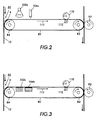
- FIG. 2 contains a detailed illustration of one embodiment of the present invention, depicting one example of a heat source and a cooling source that may be used to practice the present invention.
- FIG. 3 contains a detailed illustration of a second embodiment of the present invention, depicting another example of a heat source and a cooling source that may be used to practice the present invention.
- reproduction machine 10 employs belt 12 having a photoconductive surface deposited on a conductive substrate. Initially, belt 12 passes through charging station 20. At charging station 20, a corona generating device 14 charges the photoconductive surface of belt 12 to a relatively high, substantially uniform potential.
- an original document 16 is placed upon a transparent support platen 18.
- An illumination assembly indicated generally by the reference numeral 22, illuminates the original document 16 on platen 18 to produce image rays corresponding to the document information areas.
- the image rays are projected by means of an optical system onto the charged portion of the photoconductive surface.
- the light image dissipates the charge in selected areas to record an electrostatic latent image 2 (not shown) on the photoconductive surface corresponding to the original document informational areas.
- belt 12 advances it to development station 40.
- roller 24, rotating in the direction of arrow 26, advances a liquid developer material 28 from the chamber of housing 32 to development zone 34.
- An electrode 16 positioned before the entrance to development zone 34 is electrically biased to generate an AC field just prior to the entrance to development zone 34 so as to disperse the toner particles substantially uniformly throughout the carrier liquid.
- the toner particles, disseminated through the carrier liquid pass by electrophoresis to electrostatic latent image 2.
- the charge of the toner particles is opposite in polarity to the charge on the photoconductive surface.
- Development station 40 includes image conditioning roller 38.
- Roller 38 encounters the developed image 4 on belt 12 and conditions the image by removing and reducing liquid content of the image, while inhibiting and preventing the solid toner particles from leaving the image.
- the roller 38 also conditions the image by electrostatically compacting the toner particles of the image. Thus, an increase in percent solids is achieved in the developed image, thereby improving the quality of the final image.
- Roller 38 is placed in pressure contact against the blotter roller, to squeeze the absorbed carrier liquid from the blotter roller for deposit into a receptacle.
- An electrical potential is applied to roller 38 from a high voltage bias supply 46.
- the electric field having the same sign polarity as the toner particles, repels the toner particles of the image and inhibits their entry to the roller 38.
- roller 38 rotates in direction 44 to encounter a "wet" image on belt 12.
- the body of roller 38 absorbs excess liquid from the surface of the image through the skin covering, while conditioning the image on belt 12.
- Roller 38, discharged of excess liquid continues to rotate in direction 44 to provide a continuous absorption of liquid from the image on belt 12.
- the developed liquid image 4 is electrostatically transferred to an intermediate member or belt indicated generally by the reference numeral 80.
- Intermediate belt 80 is entrained about spaced rollers 82 and 84.
- Intermediate belt 80 moves in the direction of arrow 88.
- Bias transfer roller 86 imposes intermediate belt 80 against belt 12 to assure image transfer to the intermediate belt 80.
- the thermal control apparatus of the present invention is represented generally by reference numeral 96, the details of which will be described below.
- the invention applies heat and cooling to developed image 4 in rapid sequence, thereby increasing the solid particle content of the liquid.
- Heat is first applied to melt the solid particles, allowing them to become meshed together in the surrounding fluid.
- Subsequent cooling causes the melted particles to strengthen their interparticle bonds by taking on a solid form.
- Generating a solid developed image facilitates transfer of an accurate reproduction of the original image to hardcopy output.
- developed image 4 moves past High Solid Image Conditioning (HSIC) 94, which increases the solid particle content of a contacting image by exerting a high pressure on the image.
- HSIC High Solid Image Conditioning
- the magnitude of the pressure applied is dependent on the characteristics of the toner contained in the liquid developer material. For example, successful results have been achieved by exerting a pressure of 250 psi on a liquid containing Mark II Liquid toner.
- Mark II Liquid toner is described in detail in US-A 5,604,075 to Larson et al. issued February 18, 1997, and in US-A 5,559,558 to Larson et al. issued September 24, 1997. The contents of these references are hereby incorporated by reference. It should be kept in mind that Mark II Liquid toner is merely one example of a toner that may be transported in a liquid carrier medium, and the invention is not limited to this embodiment.
- an additional conditioning roller shown as blotter roller 76 conditions developed image 4 on belt 80 by electrostatically compressing the image, and additionally reducing the liquid content of the image, while preventing toner particles from departing from the image.
- roller 76 rotates in direction 78 to impose against the image on belt 80.
- the body of roller 76 absorbs liquid from the surface of the image.
- the absorbed liquid permeates through roller 76 and into the inner hollow cavity, where a vacuum system 90 draws the liquid from the roller 76 into a liquid receptacle (not shown) or some other location which will allow for either disposal or recirculation of the carrier liquid.
- Roller 76, discharged of excess liquid continues to rotate in direction 78 to provide a continuous absorption of liquid from images on transfer belt 80.
- Belt 80 then advances the developed image to transfer/fusing station 60.
- a copy sheet 48 is advanced from stack 52 by a sheet transport mechanism, indicated generally by the reference numeral 54.
- Developed image 4 on the photoconductive surface of belt 80 is attracted to copy sheet 48, and is simultaneously heated and fused to the sheet by heat from roller 82, for example.
- conveyor belt 45 moves the copy sheet 48 to the discharge output tray 68.
- FIG. 1 shows only a single roller 78, multiple roller stations can be utilized in conjunction with a single belt or with the transfer of multiple images to an intermediate belt 80.
- the present invention controls the forces within the developer material such that the cohesiveness of developed image 4 is sufficient to resist the force of attraction that is applied by the blotter.
- developed image 4 is transferred from photoreceptor 12 to belt 80 at transfer station 50.
- One embodiment includes transport of belt 80 with developed image 4 thereon, via rollers 82 and 84 through a path in the direction indicated by arrow 112.
- Developed image 4 is first heated by a heat source to provide a melting transition to the toner particles, particularly coalescing toner particles.
- the heat source may be a heat lamp 102a as shown in FIG. 2.
- the heat source may be a heat exchanger 102b, as depicted in FIG. 3.
- the image should be heated to its transition point, thereby allowing the chemical bonds within the solid toner particles to break down. Therefore, the temperature to which the image should be heated is dependent upon the type of toner particles that are present in the carrier medium. In the case of Mark II toner described above, the image must typically be heated to between 75°C and 100°C.
- cooling is usually required because most types of photoreceptors 12 cannot sustain the required electrostatic charge if its surface temperature is allowed to become too high. If the photoreceptor used in the reproduction system can sustain a high surface temperature, the cooling step will not be required.
- typical methods of cooling the image include the use of air knife 104a, shown in FIG. 2, and cold air exchanger 104b, illustrated in FIG. 3. It should be noted that practice of the invention does not require heat lamp 102a and air knife 104a to be used together within a single system, nor does it require heat exchanger 102b and cold air exchanger 104b to be used together.
- heat lamp 102a and cold air exchanger 104b may be used in a single system, as may heat exchanger 102b and air knife 104a.
- numerous other heating and cooling apparatus' are available, and may successfully be used, and the invention is not limited to these embodiments.
- cooling of the image immediately after it is heated causes the melted image to re-solidify, enabling the mechanical strength between the particles to be sufficient to overcome the force of adhesion between the blotter and the image, thereby eliminating image offset.
- the image must be cooled to the point that it will transition from liquid to solid form.
- the temperature to which the image must be cooled is dependent upon the type of toner particles that are present in the carrier medium.
- typical temperatures will range from room temperature (approximately 21°C) to about 60°C.
- the exact amount of cooling required for re-solidification of the melted image will be dependent upon the point at which image cohesion becomes stronger than the attraction between the image and the blotter. This will be dependent upon the mechanical durability and reliability of the blotter material at elevated temperatures as well as the heat transfer requirements of the imaging system.
Landscapes
- Physics & Mathematics (AREA)
- General Physics & Mathematics (AREA)
- Electrostatic Charge, Transfer And Separation In Electrography (AREA)
- Wet Developing In Electrophotography (AREA)
Abstract
A method and apparatus for improving the quality of an image that has
been developed by a liquid carrier is disclosed in which thermal control is used
to heat and cool the image in rapid succession, thereby increasing the
cohesiveness of the solid particles contained in the liquid carrier.
Description
The present invention is directed to a method and apparatus for improving
the quality of an image that is developed by a liquid carrier.
More specifically, the present invention is directed to a method and
apparatus for increasing the strength of an intermediate image by using thermal
control to heat and cool the image in rapid succession to increase image
cohesiveness.
Generally, the process of electrostatographic copying is initiated by
exposing a light image of an original document to a substantially uniformly
charged photoreceptive member. Exposing the charged photoreceptive member
to a light image discharges its surface in areas which correspond to non-image
areas in the original document while maintaining the charge in image areas. This
selective discharging scheme results in the creation of an electrostatic latent
image of the original document on the surface of the photoreceptive member.
This latent image is subsequently developed into a visible image by a process in
which developer material is deposited onto the surface of the photoreceptive
member. Typically, this developer material comprises carrier granules having
toner particles adhering triboelectrically thereto, wherein the toner particles are
electrostatically attracted from the carrier granules to the latent image for forming
a powder toner image on the photoreceptive member.
Alternatively, liquid developer materials comprising a liquid carrier
material having toner particles dispersed therein have been utilized. In a process
such as this, the developer material is applied to the latent image with the toner
particles being attracted toward the image areas to form a liquid image.
Regardless of the type of developer material employed, the toner particles of the
developed image are subsequently transferred from the photoreceptive member
to a copy sheet, either directly or by way of an intermediate transfer member.
Once on the copy sheet, the image may be permanently affixed to provide a "hard
copy" reproduction of the original document or file. The photoreceptive member
is then cleaned to remove any charge and/or residual developing material from
its surface in preparation for subsequent imaging cycles.
The above described electrostatographic reproduction process is well known and is useful for light lens copying from an original, as well as for printing applications involving electronically generated or stored originals. Analogous processes also exist in other printing applications such as, for example, digital laser printing where a latent image is formed on the photoconductive surface via a modulated laser beam, or ionographic printing and reproduction where charge is deposited on a charge retentive surface in response to electronically generated or stored images. Some of these printing processes develop toner on the discharged area, known as DAD, or "write black" systems, in contradistinction to the light lens generated image systems which develop toner on the charged areas, knows as CAD, or "write white" systems. The subject invention applies to both such systems.
The above described electrostatographic reproduction process is well known and is useful for light lens copying from an original, as well as for printing applications involving electronically generated or stored originals. Analogous processes also exist in other printing applications such as, for example, digital laser printing where a latent image is formed on the photoconductive surface via a modulated laser beam, or ionographic printing and reproduction where charge is deposited on a charge retentive surface in response to electronically generated or stored images. Some of these printing processes develop toner on the discharged area, known as DAD, or "write black" systems, in contradistinction to the light lens generated image systems which develop toner on the charged areas, knows as CAD, or "write white" systems. The subject invention applies to both such systems.
The use of liquid developer materials in imaging processes is well known.
Likewise, the art of developing electrostatographic latent images formed on a
photoconductive surface with liquid developer materials is also well known.
Indeed, various types of liquid developing material development systems have
heretofore been disclosed.
When using liquid toners, there is a need to remove the liquid carrier
medium from the photoconductive surface after the toner has been applied
thereto. This prevents the liquid carrier from being transferred from the
photoreceptor to the paper or to the intermediate medium during image transfer.
Removing the liquid carrier also allows it to be recovered for recycle and reuse
in the developer system. This provides for additional cost savings in terms of
printing supplies, and helps eliminate environmental and health concerns which
result from disposal of excess liquid carrier medium.
One way to remove excess carrier fluid is to place a blotter roll in
rotatable contact with the image while it resides on the intermediate substrate.
Removal of carrier fluid results in an increase in solid particle content, thereby
allowing for greater efficiency of the process of transferring the image from
intermediate substrate to permanent media. The solid content of the toner
particles can be further increased if a high pressure blotter roll is used. The most
efficient conditioning of an image to increase the percentage of solids residing
therein obviously requires removing carrier liquid while preventing the solid
toner particles from leaving the image. Successful image conditioning also
requires electrostatically compressing or compacting the toner particles in order
to physically stabilize the image, and produce a clear, high resolution image.
Each of these processes must be completed without disturbing the toner image.
In addition, the carrier liquid removal device must also remain clean and free of
toner particles so as to prevent it from thereafter contaminating a subsequent
image with embedded toner particles.
Various techniques and devices have been devised for conditioning the
liquid developer image by using blotter rolls or rollers to remove carrier liquid
from the image as discussed above. Use of a high pressure blotter has shown to
increase the solid particle content from approximately 25% to approximately
50%. While this approach has been quite effective, it requires the intermediate
substrate to pass through a high pressure nip, which places a very high load on
the intermediate substrate. Passing the substrate through a high pressure nip can
cause a substantial amount of the image to be offset to the blotter surface when
the input image reaches a certain thickness.
The following disclosures may be relevant to various aspects of the
present invention:
US-A 5,558,970 to Landa et al. issued September 24, 1996 discloses a
method of generating an image having enhanced cohesiveness by treating the
image with heat, ultraviolet radiation or chemical agents prior to transfer of the
image from a photoconductor.
US-A 5,493,373 to Gundlach et al. issued Feb. 20, 1996 discloses a
method and apparatus for printing using an intermediate member acting as a
receptor for marking particles representing an image. The marking particles may
be deposited directly or indirectly on the member, after which time the member
is exposed, via an internal heat source, to an elevated temperature sufficient to
cause the melting and coalescing of the marking particles. Subsequently, the
intermediate member is advanced so as to place the tackified marking particles
present on the outer surface thereof into intimate contact with the surface of a
recording sheet.
US-A 5,426,491 to Landa et al. issued June 20, 1995 discloses an imaging process including the steps of forming an electrostatic image on a photoconductor surface, developing the electrostatic image with a liquid developer to form a developed image on the photoconductor surface, and transferring the developed image from the photoconductor surface to a final substrate. The cohesiveness of the developed image on the photoconductor surface is enhanced by the application of heat, ultraviolet radiation or a catalytic agent to the developed image on the photoconductor surface.
US-A 5,426,491 to Landa et al. issued June 20, 1995 discloses an imaging process including the steps of forming an electrostatic image on a photoconductor surface, developing the electrostatic image with a liquid developer to form a developed image on the photoconductor surface, and transferring the developed image from the photoconductor surface to a final substrate. The cohesiveness of the developed image on the photoconductor surface is enhanced by the application of heat, ultraviolet radiation or a catalytic agent to the developed image on the photoconductor surface.
US-A 5,028,964 to Landa et al. issued July 2, 1991 discloses an apparatus
for image transfer including an image bearing surface arranged to support a liquid
toner image thereon, including image regions and background regions, means for
removing pigmented toner particles from the vicinity of background regions
defined on the image bearing surface, means for rigidizing the toner image at the
image regions, and an intermediate transfer member for receiving the toner image
from the image bearing surface after rigidization thereof, for transfer of the image
to a substrate. Means for rigidizing the toner image at the image regions include
electrifying a squeegee roller to a high voltage with a polarity that is the same as
the polarity of the charged toner, and urging the squeegee roller against the image
bearing surface.
All of the references cited herein are incorporated by reference for their
teachings.
In accordance with the present invention, there is provided an apparatus
for increasing the solid particle content of an image that has been developed using
a liquid developer containing solid toner particles residing in a liquid carrier
material, comprising:
In accordance with another aspect of the invention, there is provided a
method of increasing the solid particle content of an image that has been
developed with a liquid developer containing solid toner particles residing in a
liquid carrier material, which includes: transferring an image that has been
developed by the liquid developer to a substrate; transporting said substrate with
said liquid developed image thereon along a path; heating said image, thereby
causing the solid toner particles to melt; and immediately cooling said image,
thereby causing said melted toner particles to re-solidify.
Liquid developers have many advantages, and often produce images of
higher quality than images formed with dry toners. For example, images
developed with liquid developers can be made to adhere to paper without a fixing
or fusing step, thereby eliminating a requirement to include a resin in the liquid
developer for fusing purposes. In addition, the toner particles can be made to be
very small without resulting in problems often associated with small particle
powder toners, such as airborne contamination which can adversely affect
machine reliability and can create potential health hazards. Development with
liquid developers in full color imaging processes also has many advantages,
including, among others, production of a texturally attractive output document
due to minimal multilayer toner height build-up (whereas full color images
developed with dry toners often exhibit substantial height build-up of the image
in regions where color areas overlap). In addition, full color imaging with liquid
developers is economically attractive, particularly if surplus liquid carrier
containing the toner particles can be economically recovered without cross
contamination of colorants. Further, full color prints made with liquid developers
can be processed to a substantially uniform finish, whereas uniformity of finish
is difficult to achieve with powder toners due to variations in the toner pile height
as well as a need for thermal fusion, among other factors.
Embodiments of the present invention will now be described, by way of
example, with reference to the accompanying drawings, in which:
FIG. 1 contains a schematic illustration of a portion of an
electrophotographic printing machine which uses an intermediate transfer belt to
complete liquid image development.
FIG. 2 contains a detailed illustration of one embodiment of the present
invention, depicting one example of a heat source and a cooling source that may
be used to practice the present invention.
FIG. 3 contains a detailed illustration of a second embodiment of the
present invention, depicting another example of a heat source and a cooling
source that may be used to practice the present invention.
The present invention is directed to a method and apparatus for improving
the quality of an image that is developed by a liquid carrier. More specifically,
the present invention is directed to a method and apparatus for increasing the
strength of an intermediate image by using thermal control to heat and cool the
image in rapid succession to increase image cohesiveness.
Referring now to the drawings where the showings are for the purpose of describing an embodiment of the invention and not for limiting same, in FIG. 1,reproduction machine 10 employs belt 12 having a photoconductive surface
deposited on a conductive substrate. Initially, belt 12 passes through charging
station 20. At charging station 20, a corona generating device 14 charges the
photoconductive surface of belt 12 to a relatively high, substantially uniform
potential.
Referring now to the drawings where the showings are for the purpose of describing an embodiment of the invention and not for limiting same, in FIG. 1,
Once the photoconductive surface of belt 12 is charged, the charged
portion is advanced to exposure station 30. At exposure station 30, an original
document 16 is placed upon a transparent support platen 18. An illumination
assembly, indicated generally by the reference numeral 22, illuminates the
original document 16 on platen 18 to produce image rays corresponding to the
document information areas. The image rays are projected by means of an optical
system onto the charged portion of the photoconductive surface. The light image
dissipates the charge in selected areas to record an electrostatic latent image 2
(not shown) on the photoconductive surface corresponding to the original
document informational areas.
After electrostatic latent image 2 has been recorded, belt 12 advances it
to development station 40. At development station 40, roller 24, rotating in the
direction of arrow 26, advances a liquid developer material 28 from the chamber
of housing 32 to development zone 34. An electrode 16 positioned before the
entrance to development zone 34 is electrically biased to generate an AC field
just prior to the entrance to development zone 34 so as to disperse the toner
particles substantially uniformly throughout the carrier liquid. The toner particles,
disseminated through the carrier liquid, pass by electrophoresis to electrostatic
latent image 2. The charge of the toner particles is opposite in polarity to the
charge on the photoconductive surface.
In operation, roller 38 rotates in direction 44 to encounter a "wet" image
on belt 12. The body of roller 38 absorbs excess liquid from the surface of the
image through the skin covering, while conditioning the image on belt 12. Roller
38, discharged of excess liquid, continues to rotate in direction 44 to provide a
continuous absorption of liquid from the image on belt 12.
At transfer station 50, the developed liquid image 4 is electrostatically
transferred to an intermediate member or belt indicated generally by the reference
numeral 80. Intermediate belt 80 is entrained about spaced rollers 82 and 84.
Intermediate belt 80 moves in the direction of arrow 88. Bias transfer roller 86
imposes intermediate belt 80 against belt 12 to assure image transfer to the
intermediate belt 80.
The thermal control apparatus of the present invention is represented
generally by reference numeral 96, the details of which will be described below.
Briefly, the invention applies heat and cooling to developed image 4 in rapid
sequence, thereby increasing the solid particle content of the liquid. Heat is first
applied to melt the solid particles, allowing them to become meshed together in
the surrounding fluid. Subsequent cooling causes the melted particles to
strengthen their interparticle bonds by taking on a solid form. Generating a solid
developed image facilitates transfer of an accurate reproduction of the original
image to hardcopy output. Once this thermal treatment has been completed,
developed image 4 moves past High Solid Image Conditioning (HSIC) 94, which
increases the solid particle content of a contacting image by exerting a high
pressure on the image. The magnitude of the pressure applied is dependent on the
characteristics of the toner contained in the liquid developer material. For
example, successful results have been achieved by exerting a pressure of 250 psi
on a liquid containing Mark II Liquid toner. Mark II Liquid toner is described in
detail in US-A 5,604,075 to Larson et al. issued February 18, 1997, and in US-A
5,559,558 to Larson et al. issued September 24, 1997. The contents of these
references are hereby incorporated by reference. It should be kept in mind that
Mark II Liquid toner is merely one example of a toner that may be transported in
a liquid carrier medium, and the invention is not limited to this embodiment.
In this particular embodiment of the machine, an additional conditioning
roller shown as blotter roller 76, conditions developed image 4 on belt 80 by
electrostatically compressing the image, and additionally reducing the liquid
content of the image, while preventing toner particles from departing from the
image.
In operation,roller 76 rotates in direction 78 to impose against the image on belt
80. The body of roller 76 absorbs liquid from the surface of the image. The
absorbed liquid permeates through roller 76 and into the inner hollow cavity,
where a vacuum system 90 draws the liquid from the roller 76 into a liquid
receptacle (not shown) or some other location which will allow for either disposal
or recirculation of the carrier liquid. Roller 76, discharged of excess liquid,
continues to rotate in direction 78 to provide a continuous absorption of liquid
from images on transfer belt 80.
In operation,
After developed image 4 is transferred to copy sheet 48, residual liquid
developer material remains adhering to the photoconductive surface of belt 12.
A cleaning roller 72 formed of any appropriate synthetic resin, is driven in a
direction opposite to the direction of movement of belt 12 to scrub the
photoconductive surface clean. It is understood, however, that a number of
photoconductor cleaning means exist in the art, any of which would be suitable
for use with the present invention. Any residual charge left on the
photoconductive surface is extinguished by flooding the photoconductive surface
with light from lamps 74. Although the apparatus shown in FIG. 1 shows only
a single roller 78, multiple roller stations can be utilized in conjunction with a
single belt or with the transfer of multiple images to an intermediate belt 80.
Referring now to FIG. 2, the present invention controls the forces within
the developer material such that the cohesiveness of developed image 4 is
sufficient to resist the force of attraction that is applied by the blotter. As
indicated above, developed image 4 is transferred from photoreceptor 12 to belt
80 at transfer station 50. One embodiment includes transport of belt 80 with
developed image 4 thereon, via rollers 82 and 84 through a path in the direction
indicated by arrow 112. Developed image 4 is first heated by a heat source to
provide a melting transition to the toner particles, particularly coalescing toner
particles.
In one embodiment, the heat source may be a heat lamp 102a as shown
in FIG. 2. Alternatively, the heat source may be a heat exchanger 102b, as
depicted in FIG. 3. The image should be heated to its transition point, thereby
allowing the chemical bonds within the solid toner particles to break down.
Therefore, the temperature to which the image should be heated is dependent
upon the type of toner particles that are present in the carrier medium. In the case
of Mark II toner described above, the image must typically be heated to between
75°C and 100°C.
Most often heating by lamp 102a or exchanger 102b will immediately
followed by cooling. Cooling is usually required because most types of
photoreceptors 12 cannot sustain the required electrostatic charge if its surface
temperature is allowed to become too high. If the photoreceptor used in the
reproduction system can sustain a high surface temperature, the cooling step will
not be required. In those cases where a high temperature photoreceptor is not
available, typical methods of cooling the image include the use of air knife 104a,
shown in FIG. 2, and cold air exchanger 104b, illustrated in FIG. 3. It should be
noted that practice of the invention does not require heat lamp 102a and air knife
104a to be used together within a single system, nor does it require heat
exchanger 102b and cold air exchanger 104b to be used together. Those skilled
in the art will recognize that heat lamp 102a and cold air exchanger 104b may be
used in a single system, as may heat exchanger 102b and air knife 104a. In fact,
those skilled in the art will recognize that numerous other heating and cooling
apparatus' are available, and may successfully be used, and the invention is not
limited to these embodiments.
In any event, cooling of the image immediately after it is heated causes the melted image to re-solidify, enabling the mechanical strength between the particles to be sufficient to overcome the force of adhesion between the blotter and the image, thereby eliminating image offset. The image must be cooled to the point that it will transition from liquid to solid form. As was the case with heating of the image, the temperature to which the image must be cooled is dependent upon the type of toner particles that are present in the carrier medium. Continuing with the example of Mark II toner, typical temperatures will range from room temperature (approximately 21°C) to about 60°C. The exact amount of cooling required for re-solidification of the melted image will be dependent upon the point at which image cohesion becomes stronger than the attraction between the image and the blotter. This will be dependent upon the mechanical durability and reliability of the blotter material at elevated temperatures as well as the heat transfer requirements of the imaging system.
In any event, cooling of the image immediately after it is heated causes the melted image to re-solidify, enabling the mechanical strength between the particles to be sufficient to overcome the force of adhesion between the blotter and the image, thereby eliminating image offset. The image must be cooled to the point that it will transition from liquid to solid form. As was the case with heating of the image, the temperature to which the image must be cooled is dependent upon the type of toner particles that are present in the carrier medium. Continuing with the example of Mark II toner, typical temperatures will range from room temperature (approximately 21°C) to about 60°C. The exact amount of cooling required for re-solidification of the melted image will be dependent upon the point at which image cohesion becomes stronger than the attraction between the image and the blotter. This will be dependent upon the mechanical durability and reliability of the blotter material at elevated temperatures as well as the heat transfer requirements of the imaging system.
It is, therefore, apparent that there has been provided in accordance with
the present invention, a method and apparatus for increasing the mechanical
strength of a developed liquid image that fully satisfies the aims and advantages
hereinbefore set forth. While this invention has been described in conjunction
with a specific embodiment thereof, it is evident that many alternatives,
modifications, and variations will be apparent to those skilled in the art.
Accordingly, it is intended to embrace all such alternatives, modifications and
variations that fall within the spirit and broad scope of the appended claims.
Claims (10)
- An apparatus for increasing the solid particle content of an image that has been developed using a liquid developer containing solid toner particles residing in a liquid carrier material, comprising:a) means (50) for transferring the image (4) to a substrate (80);b) means (82, 84) for transporting said substrate (80) with said liquid developed image (4) thereon along a path (112, 113);c) means (102a, 102b) for heating said image (4), thereby causing the solid toner particles to melt; andd) means (104a, 104b) for immediately cooling said image (4), thereby causing said melted toner particles to re-solidify.
- An apparatus as claimed in claim 1 wherein said heating means comprises is a heat lamp.
- An apparatus as claimed in claim 1 wherein said heating means comprises a heat exchanger.
- An apparatus as claimed in claims 1, 2 or 3, wherein said cooling means comprises an air knife.
- An apparatus as claimed in claims 1, 2 or 3, wherein said cooling means comprises a cold air exchanger.
- A method of increasing the solid particle content of an image that has been developed with a liquid developer containing solid toner particles residing in a liquid carrier material, comprising:a) transferring an image (4) that has been developed by the liquid developer to a substrate (80);b) transporting said substrate (80) with said liquid developed image (4) thereon along a path (112, 113);c) heating said image, thereby causing the solid toner particles to melt; andd) immediately cooling said image, thereby causing said melted toner particles to re-solidify.
- A method as claimed in claim 6 wherein said heating step comprises increasing the temperature of said image to at least a solid to liquid transition temperature for the solid toner particles.
- A method as claimed in claim 7 wherein said solid to liquid transition temperature is between 80°C and 100°C.
- A method as claimed in claims 7 or 8 wherein said cooling step comprises decreasing the temperature of said image to at least a liquid to solid transition temperature for said melted toner particles.
- A method as claimed in claim 9 wherein said liquid to solid transition temperature is between 21°C and 60°C.
Applications Claiming Priority (2)
| Application Number | Priority Date | Filing Date | Title |
|---|---|---|---|
| US874591 | 1978-02-02 | ||
| US08/874,591 US5832352A (en) | 1997-06-13 | 1997-06-13 | Method and apparatus for increasing the mechanical strength of intermediate images for liquid development image conditioning |
Publications (1)
| Publication Number | Publication Date |
|---|---|
| EP0884655A1 true EP0884655A1 (en) | 1998-12-16 |
Family
ID=25364132
Family Applications (1)
| Application Number | Title | Priority Date | Filing Date |
|---|---|---|---|
| EP98303392A Withdrawn EP0884655A1 (en) | 1997-06-13 | 1998-04-30 | Method and apparatus for increasing the mechanical strength of liquid developed image on an intermediate transfer member |
Country Status (3)
| Country | Link |
|---|---|
| US (1) | US5832352A (en) |
| EP (1) | EP0884655A1 (en) |
| JP (1) | JPH1115279A (en) |
Families Citing this family (7)
| Publication number | Priority date | Publication date | Assignee | Title |
|---|---|---|---|---|
| US5991582A (en) * | 1998-11-02 | 1999-11-23 | Xerox Corporation | Method and apparatus for developing high quality images in a liquid immersion development machine |
| GB9923496D0 (en) * | 1999-10-06 | 1999-12-08 | Xeikon Nv | Single-pass multi-colour printer and method of printing |
| US6411793B1 (en) * | 2001-02-20 | 2002-06-25 | Xerox Corporation | Transfix component having outer layer of haloelastomer with pendant hydrocarbon groups |
| JP2004333633A (en) * | 2003-05-01 | 2004-11-25 | Pfu Ltd | Liquid electrophotographic equipment |
| CN102530400A (en) * | 2010-12-17 | 2012-07-04 | 华硕电脑股份有限公司 | packaging structure |
| JP2013120213A (en) * | 2011-12-06 | 2013-06-17 | Ricoh Co Ltd | Image forming method and image forming apparatus |
| DE102016104939B3 (en) * | 2016-03-17 | 2017-06-01 | Océ Holding B.V. | Conditioning unit for conditioning a toner image |
Citations (5)
| Publication number | Priority date | Publication date | Assignee | Title |
|---|---|---|---|---|
| US5200285A (en) * | 1990-03-20 | 1993-04-06 | Delphax Systems, Inc. | System and method for forming multiply toned images |
| JPH05165350A (en) * | 1991-12-17 | 1993-07-02 | Konica Corp | Fixing device |
| US5559588A (en) * | 1995-09-13 | 1996-09-24 | Xerox Corporation | Lid machine capable of producing clean-background stabilized liquid toner images |
| US5558970A (en) * | 1988-11-17 | 1996-09-24 | Indigo N.V. | Enhancing cohesiveness of developed images |
| EP0775948A1 (en) * | 1995-11-24 | 1997-05-28 | Xeikon Nv | Single pass, multi-colour electrostatographic printer |
Family Cites Families (6)
| Publication number | Priority date | Publication date | Assignee | Title |
|---|---|---|---|---|
| US5028964A (en) * | 1989-02-06 | 1991-07-02 | Spectrum Sciences B.V. | Imaging system with rigidizer and intermediate transfer member |
| DE69119612T2 (en) * | 1991-03-26 | 1996-12-12 | Indigo Nv | IMAGE GENERATION SYSTEM WITH AN INTERMEDIATE TRANSFER ELEMENT |
| US5493373A (en) * | 1993-05-03 | 1996-02-20 | Xerox Corporation | Method and apparatus for imaging on a heated intermediate member |
| US5414498A (en) * | 1993-09-14 | 1995-05-09 | Delphax Systems | Liquid/dry toner imaging system |
| EP0686894B1 (en) * | 1993-12-28 | 1999-10-13 | Sony Corporation | Image formation apparatus |
| JPH08129310A (en) * | 1994-10-31 | 1996-05-21 | Hitachi Ltd | Electrophotographic equipment |
-
1997
- 1997-06-13 US US08/874,591 patent/US5832352A/en not_active Expired - Fee Related
-
1998
- 1998-04-30 EP EP98303392A patent/EP0884655A1/en not_active Withdrawn
- 1998-06-08 JP JP10159273A patent/JPH1115279A/en not_active Withdrawn
Patent Citations (5)
| Publication number | Priority date | Publication date | Assignee | Title |
|---|---|---|---|---|
| US5558970A (en) * | 1988-11-17 | 1996-09-24 | Indigo N.V. | Enhancing cohesiveness of developed images |
| US5200285A (en) * | 1990-03-20 | 1993-04-06 | Delphax Systems, Inc. | System and method for forming multiply toned images |
| JPH05165350A (en) * | 1991-12-17 | 1993-07-02 | Konica Corp | Fixing device |
| US5559588A (en) * | 1995-09-13 | 1996-09-24 | Xerox Corporation | Lid machine capable of producing clean-background stabilized liquid toner images |
| EP0775948A1 (en) * | 1995-11-24 | 1997-05-28 | Xeikon Nv | Single pass, multi-colour electrostatographic printer |
Non-Patent Citations (1)
| Title |
|---|
| PATENT ABSTRACTS OF JAPAN vol. 017, no. 573 (P - 1630) 19 October 1993 (1993-10-19) * |
Also Published As
| Publication number | Publication date |
|---|---|
| JPH1115279A (en) | 1999-01-22 |
| US5832352A (en) | 1998-11-03 |
Similar Documents
| Publication | Publication Date | Title |
|---|---|---|
| EP0887714B1 (en) | Electrostatic image development | |
| EP0249385B1 (en) | An intermediate transfer apparatus | |
| US3591276A (en) | Method and apparatus for offset xerographic reproduction | |
| US4796048A (en) | Resilient intermediate transfer member and apparatus for liquid ink development | |
| US5434029A (en) | Curl prevention method for high TMA color copiers | |
| EP0929017A2 (en) | Electrostatic latent image formation | |
| US5233397A (en) | Thermal transfer apparatus | |
| JPS62260174A (en) | Electrophotographic type copying machine adapted to fix liquid image with roller | |
| US5708950A (en) | Transfuser | |
| EP0294123B1 (en) | A liquid ink transfer system | |
| US5832352A (en) | Method and apparatus for increasing the mechanical strength of intermediate images for liquid development image conditioning | |
| EP0887716B1 (en) | Electrostatic latent image development | |
| US5937248A (en) | Contact electrostatic printing image forming method and apparatus using image area centered patch of tonerpatches of toner | |
| JP3621447B2 (en) | Heat and pressure fuser and toner image fixing method | |
| US6122471A (en) | Method and apparatus for delivery of high solids content toner cake in a contact electrostatic printing system | |
| US5559592A (en) | Sintered image transfer system | |
| US5530534A (en) | Transfusing assembly | |
| US5142327A (en) | Electrophotographic copying process using two image areas | |
| US4339194A (en) | Cold pressure fusing apparatus | |
| US5987283A (en) | Apparatus and method for developing an electrostatic latent image directly from an imaging member to a final substrate | |
| US6006061A (en) | Method and apparatus for forming high quality images in an electrostatic printing machine | |
| JPH07210020A (en) | Heating and pressurization fuser and fixing method | |
| US3984182A (en) | Pretransfer conditioning for electrostatic printing | |
| US5991582A (en) | Method and apparatus for developing high quality images in a liquid immersion development machine | |
| US6185399B1 (en) | Multicolor image-on-image forming machine using air breakdown charge and development (ABCD) Process |
Legal Events
| Date | Code | Title | Description |
|---|---|---|---|
| PUAI | Public reference made under article 153(3) epc to a published international application that has entered the european phase |
Free format text: ORIGINAL CODE: 0009012 |
|
| AK | Designated contracting states |
Kind code of ref document: A1 Designated state(s): DE FR GB |
|
| AX | Request for extension of the european patent |
Free format text: AL;LT;LV;MK;RO;SI |
|
| 17P | Request for examination filed |
Effective date: 19990616 |
|
| AKX | Designation fees paid |
Free format text: DE FR GB |
|
| 17Q | First examination report despatched |
Effective date: 20020322 |
|
| STAA | Information on the status of an ep patent application or granted ep patent |
Free format text: STATUS: THE APPLICATION HAS BEEN WITHDRAWN |
|
| 18W | Application withdrawn |
Withdrawal date: 20020807 |