EP0884608B1 - Seismic surveying - Google Patents
Seismic surveying Download PDFInfo
- Publication number
- EP0884608B1 EP0884608B1 EP98304431A EP98304431A EP0884608B1 EP 0884608 B1 EP0884608 B1 EP 0884608B1 EP 98304431 A EP98304431 A EP 98304431A EP 98304431 A EP98304431 A EP 98304431A EP 0884608 B1 EP0884608 B1 EP 0884608B1
- Authority
- EP
- European Patent Office
- Prior art keywords
- signals
- water
- receiver
- source
- location
- Prior art date
- Legal status (The legal status is an assumption and is not a legal conclusion. Google has not performed a legal analysis and makes no representation as to the accuracy of the status listed.)
- Expired - Lifetime
Links
Images


Classifications
-
- G—PHYSICS
- G01—MEASURING; TESTING
- G01V—GEOPHYSICS; GRAVITATIONAL MEASUREMENTS; DETECTING MASSES OR OBJECTS; TAGS
- G01V1/00—Seismology; Seismic or acoustic prospecting or detecting
- G01V1/38—Seismology; Seismic or acoustic prospecting or detecting specially adapted for water-covered areas
- G01V1/3808—Seismic data acquisition, e.g. survey design
-
- G—PHYSICS
- G01—MEASURING; TESTING
- G01V—GEOPHYSICS; GRAVITATIONAL MEASUREMENTS; DETECTING MASSES OR OBJECTS; TAGS
- G01V1/00—Seismology; Seismic or acoustic prospecting or detecting
- G01V1/28—Processing seismic data, e.g. for interpretation or for event detection
- G01V1/36—Effecting static or dynamic corrections on records, e.g. correcting spread; Correlating seismic signals; Eliminating effects of unwanted energy
- G01V1/364—Seismic filtering
Definitions
- U.S. Patent No. 4,979,150 issued to present co-inventor Barr, and entitled "Method for Attenuation of Water-Column Reverberations" describes a Dual Sensor bottom cable method for attenuating the unwanted water column reverberations associated with each reflection signal in the seismic data by combining the pressure and velocity signals recorded at each receiver station.
- the scale factor requires determining the water bottom reflectivity, which depends upon the acoustic impedance of the bottom material.
- the receivers 114 detect both reflected waves of interest and unwanted reverberated waves which are noise.
- Reverberated waves are seismic waves which reflect off the water-air interface at the surface 116 of the water one or more times before finally traveling downwardly in the water 106 to impinge on the receivers 114 .
- An example of reverberated waves is illustrated by the rays 132 in Fig. 1 .
- Peg-leg reverberation waves contain at least one reflection from an interface 122 between strata in addition to the reverberations between the water surface 116 and the marine bottom 112 .
- the order of the peg-leg is the number of reflections from interfaces between strata.
- the peg-leg source and receiver sequences can be eliminated by multiplying the up-going signal Up(Z) of Eq. (1) by the inverse split Backus filter 1 + R S ⁇ Z S ⁇ 1 + R R ⁇ Z R . Eliminating the peg-leg source and receiver sequences in Eq. (1) minimizes the total energy in the up-going signal.
- the determination of the water bottom reflectivities at the source and receiver locations translates into a search for the values R S and R R which result in the minimum signal power after multiplication with the inverse split Backus filter.
- an exhaustive search is feasible. In an exhaustive search, a series of values is selected which systematically covers the range of the possible solution space, such as values covering the range in equally-spaced increments.
- Fig. 4 illustrates a flow diagram which represents the alternative embodiment of determining surface consistent water bottom reflectivities at different source and receiver locations.
- the alternative embodiment illustrated is generally designated by 400.
- seismic waves are generated at N S source locations n.
- the seismic waves from block 402 are detected at N R receiver locations m by co-located pairs of hydrophones and geophones, generating corresponding pressure and velocity signals, respectively.
- the pairs of pressure and velocity signals from blocks 404 and 406 are summed at each receiver location m to generate summed signals for all source and receiver combinations.
Landscapes
- Life Sciences & Earth Sciences (AREA)
- Physics & Mathematics (AREA)
- Remote Sensing (AREA)
- Engineering & Computer Science (AREA)
- Geology (AREA)
- Environmental & Geological Engineering (AREA)
- Acoustics & Sound (AREA)
- General Life Sciences & Earth Sciences (AREA)
- General Physics & Mathematics (AREA)
- Geophysics (AREA)
- Oceanography (AREA)
- Geophysics And Detection Of Objects (AREA)
- Measurement Of Mechanical Vibrations Or Ultrasonic Waves (AREA)
Description
- The present invention relates to seismic surveying and, more particularly, to a method for using production Dual Sensor seismic data to determine water bottom reflectivity in a surface consistent manner, that is, determining different values at different locations.
- In marine seismic prospecting or surveying, a seismic survey ship is equipped with at least one energy source and at least one receiver for taking seismic profiles of an underwater land configuration. The act of taking profiles is often referred to as "shooting" or taking "shots" due to the fact that explosive devices had been commonly used for many years as energy sources. An energy source is designed to produce compressional waves that propagate through the water and into the underwater subterranean land formations. As the compressional waves propagate through the subterranean formations, they strike interfaces between formations, commonly referred to as strata, and reflect back through the earth and water to a receiver. The receiver typically converts the detected waves into electrical signals which are later processed into an image that provides information about the structure of the subterranean formations.
- Presently, one of the most common marine energy sources is an air gun that discharges air under very high pressure into the water. The discharged air forms an energy pulse which contains frequencies within the seismic range. Another marine energy source which is frequently used is a marine vibrator. Marine vibrators typically include a pneumatic or hydraulic actuator that causes an acoustic piston to vibrate at a range of selected frequencies.
- Just as different energy sources may be used to generate acoustic waves in marine applications, different receivers may be used to detect reflected acoustic waves. The receivers most commonly used in marine seismic prospecting are hydrophones. Hydrophones convert pressure waves into electrical signals that are used for analog or digital processing. The most common type of hydrophone includes a piezoelectric element which converts physical signals, such as pressure, into electrical signals. Hydrophones are usually mounted on a long streamer which is towed behind the survey ship at a depth of tens of feet.
- Alternatively, marine seismic prospecting may use different types of receivers which detect different characteristics of the environment. For instance, in Dual Sensor bottom cable seismic recording, a combination of pressure sensitive transducers, such as hydrophones, and particle velocity transducers, such as geophones, are deployed on the marine bottom. Geophones are typically used in land operations where metal spikes anchor the geophones to the ground to maintain correspondence of geophone motion to ground motion. In marine applications, however, anchoring the geophones is difficult. Typically, therefore, cylindrical gimbal geophones are attached to the bottom cable. After the cable is deployed from the seismic survey ship, the geophones lie in contact with the marine bottom where they fall. The gimbal mechanism inside the cylinder orients the geophone element vertically for proper operation. Typically, miles of bottom cable are deployed in a planned pattern such as a single line or several substantially parallel lines.
- The use of water bottom cables is particularly effective in obtaining full three dimensional coverage in areas too shallow or too congested with obstacles for gathering seismic data with a towed streamer. While the bottom cable technique allows access to areas denied by the towed streamer method, an additional, unwanted "ghost" reflection from the air-water interface, along with subsequent reverberations, occurs for each primary reflection wave. The time delay between the primary reflection signal and the ghost reflection signal is greater with the bottom cable method than with the towed streamer method because the detectors are farther removed from the air-water interface, except in shallow water.
- Two basic approaches have been proposed for eliminating the ghost reflection. The first approach involves recording signals from detectors at different depths and performing a wavefield separation. The second, and operationally more straightforward, approach, utilizes co-located pairs of pressure and velocity detectors, as in, for example,
U.S. Patent No. 2,757,356 , "Method and Apparatus for Canceling Reverberations in Water Layers", issued to Hagarty. This second approach capitalizes upon the fact that pressure and velocity detectors generate signals which are the same polarity for upward travelling waves but are of opposite polarity for downward travelling waves, that is, the ghost reflections. This indicates that the two signals can be properly scaled and summed to eliminate the unwanted reverberations associated with each reflection. In the frequency domain, this relationship expresses itself in the complimentary amplitude spectra of the two sensors. When the signals are properly summed, a smooth amplitude spectrum results. -
U.S. Patent No. 4,979,150 , issued to present co-inventor Barr, and entitled "Method for Attenuation of Water-Column Reverberations" describes a Dual Sensor bottom cable method for attenuating the unwanted water column reverberations associated with each reflection signal in the seismic data by combining the pressure and velocity signals recorded at each receiver station. Proper combination of the pressure and velocity signals, in order to remove the component of the signal representing energy which is trapped in the water layer, can only be performed after scaling the velocity signal by a scale factor S given by
- In the past, a calibration survey has been used to estimate the water bottom reflectivity R. In the dual sensor operations described above, an estimate of the water bottom reflectivity is made by collecting separate reference information, generated by shooting a small seismic source directly over the receivers. The collection of this survey data requires additional time and cost beyond the data acquisition phase of the survey.
-
U.S. Patents 5,396,472 and5,524,100 , both issued to present co-inventor Paffenholz, and entitled "Method for Deriving Water Bottom Reflectivity in Dual Sensor Seismic Surveys", describe a method which allows the determination of the water bottom reflectivity directly from the production Dual Sensor seismic data rather than from additional calibration data, and describe the advantages of using this method over the prior art. The advantages include deriving water bottom reflectivity from production data without relying on the ratio of the first breaks and without being affected by clipped first signals. A third advantage is in providing a method of combining trace data to eliminate peg-leg reverberations. However, while the operator used in the Paffenholz patents acknowledges the existence of source and receiver side reverberations, it is assumed that the pertinent parameters, water bottom reflectively and water depth, are similar at the source and the receiver locations. This does not yield a surface consistent map of reflectivities. - Various aspects of the present invention are exemplified by the attached claims.
- Another aspect of the present invention provides a method for determining surface consistent water bottom reflectivities using production Dual Sensor seismic data. Pressure signals and velocity signals are combined to generate combined signals having signal components representing downwardly-travelling energy substantially removed. The pressure and velocity signals correspond to seismic waves generated at source locations n in a water layer and detected by co-located pressure and velocity receivers at receiver locations m in the water layer. The combined signals correspond to each pairing of source location n and receiver location m. The combined signals are transformed from the time domain to the frequency domain, generating transformed signals. A source peg-leg term and a receiver peg-leg term are calculated for each transformed signal, generating filtered signals. An optimization algorithm is applied to the filtered signals and uses the corresponding source and receiver peg-leg terms to determine the possibly different water bottom reflectivity values Rn and Rm at each of the source locations and the receiver locations m, respectively.
- For a better understanding of the invention, and to show how the same may be carried into effect, reference will now be made, by way of example, to the accompanying drawings, in which:-
-
Fig. 1 is an illustration of apparatus used in a bottom cable operation; -
Fig. 2 is an illustration of source and receiver peg-leg reverberation sequences; -
Fig. 3 is a flow diagram of a preferred embodiment of the present invention using the inverse split Backus filter; -
Fig. 4 is a flow diagram of an alternative embodiment -of the present invention using a spectral decomposition into source and receiver components; and -
Fig. 5 is a flow diagram of an alternative embodiment of the present invention for eliminating the peg-leg multiple sequence. -
Fig. 1 illustrates a preferred marine seismic survey system, generally designated by 100. The system 100 includes aseismic survey ship 102 that is adapted for towing aseismic energy source 104 through a body ofwater 106. Theseismic energy source 104 is an acoustic energy source or an array of such sources. Anacoustic energy source 104 preferred for use with the system 100 is a compressed air gun, constructed and operated in a manner conventional in the art. The system 100 also includes areceiving ship 108 that is preferably anchored in the body ofwater 106. The receivingship 108 deploys one ormore cables 110 on themarine bottom 112, and receives signals from thecables 110. Thecables 110 carry at least onereceiver 114 each, but normally include a plurality ofreceivers 114. - The
receivers 114 include hydrophones for detecting water pressure and geophones for detecting water bottom particle velocity. More particularly, the hydrophones and geophones on thecables 110 are arranged so that each hydrophone has at least one gimballed geophone positioned next to it, when thecables 110 are deployed on themarine bottom 112. Electrical signals are sent to a recording system on the receivingship 108 from the hydrophones and geophones. Thesurvey ship 102 fires thesource 104 at predetermined locations while the signals from the hydrophones and geophones are recorded. The signals are recorded by a multi-channel seismic recording system (not shown) that selectively amplifies, conditions and records time-varying electrical signals onto magnetic tape. Advantageously, the seismic recording system also digitizes the received signals to facilitate signal analysis. Those skilled in the art will recognize that any one of a variety of seismic recording systems can be used. - According to a preferred practice, the
cables 110 and their associatedreceivers 114 carrying hydrophones and geophones are positioned on themarine bottom 112. Production shooting takes place with thesurvey ship 102 moving at a constant speed along a set of parallel lines, or swath, perpendicular to thecables 110. After thesurvey ship 102 completes the swath, the receivingship 108 or other suitable ship retrieves thecables 110 and re-deploys thecables 110 in lines spaced from, but parallel to, the previous cable locations. Once thecables 110 are re-deployed, thesurvey ship 102 shoots another swath. - During data collection, seismic waves generated by the
source 104 travel downwardly, as indicated by therays 120. These primary waves are reflected off of interfaces between strata, such as theinterface 122 betweenstrata subterranean earth formation 128. The reflected waves travel upwardly, as illustrated by therays 130. The hydrophones and geophones which comprise thereceivers 114 detect the reflected waves 130. Thereceivers 114 generate electrical signals representative of pressure and particle velocity changes in the seismic wave field, and transmit these generated electrical signals back to thesurvey ship 108 via thecable 110. The seismic recording system within thesurvey ship 108 records these electrical signals so that they can be subsequently processed to map thesubterranean earth formation 128. - The
receivers 114 detect both reflected waves of interest and unwanted reverberated waves which are noise. Reverberated waves are seismic waves which reflect off the water-air interface at thesurface 116 of the water one or more times before finally traveling downwardly in thewater 106 to impinge on thereceivers 114. An example of reverberated waves is illustrated by therays 132 inFig. 1 . Peg-leg reverberation waves contain at least one reflection from aninterface 122 between strata in addition to the reverberations between thewater surface 116 and themarine bottom 112. The order of the peg-leg is the number of reflections from interfaces between strata. -
Fig. 2 illustrates three examples of first order peg-leg reverberation sequences. A first order peg-leg reverberation sequence is defined above as a seismic wave which reaches thesubsurface interface 222 once in addition to water trapped reverberations. In the first example ofFig. 2 , the downward travellingwave 240 fromseismic energy source 204 travels downward throughwater layer 206 andstrata 224 until reflecting up frominterface 222, which provides a subsurface reflector. Next the upward travellingwave 242 travels back throughstrata 224 andwater layer 206 to thewater surface 216. Then the wave reverberates through thewater layer 206 between thewater surface 216 and themarine bottom 212 until it reachesreceiver pair 214. This first example is called a "receiver peg-leg reverberation sequence" since the reverberations in thewater layer 206 occur near thereceiver 214 location. In the second example ofFig. 2 , the downward travelling wave fromseismic energy source 204 reverberates through thewater layer 206 until the downward travelling wave 244 travels thoughwater layer 206 andstrata 224 and is reflected frominterface 222. Then upward travellingwave 246 moves back throughstrata 224 andwater layer 206 towater surface 216. There the wave again reverberates through thewater layer 206 between thewater surface 216 and themarine bottom 212 until it reachesreceiver pair 214. The second example is a regular first order peg-leg reverberation sequence. In the third example ofFig. 2 , the wave fromseismic energy source 204 first reverberates through thewater layer 206 between thewater surface 216 and themarine bottom 212. Then the downward travellingwave 248 passes throughwater layer 206 andstrata 224 until reachinginterface 222. There the wave reflects and upward travellingwave 250 passes throughstrata 224 toreceiver pair 214. This third example is called a "source peg-leg reverberation sequence" since the reverberations in thewater layer 206 occur near thesource 204 location. - A method embodying an aspect of the present invention can determine water bottom reflectivities in cases where the water depths and the water bottom reflectivities are different at the source and receiver locations. The Paffenholz
U.S. Patents 5,396,472 and5,524,100 show that if the pressure and velocity sensors are located on the water bottom, then the first order peg-leg reverberation sequences, P(Z) and V(Z), for the pressure and velocity sequences, respectively, can be expressed as

- ZS = the delay operator for a two-way trip in the water layer at the source location,
- ZR = the delay operator for a two-way trip in the water layer at the receiver location,
- RS = the water bottom reflectivity at the source location,
- RR = the water bottom reflectivity at the receiver location, and
- β = the earth reflectivity sequence and the source wavelet.
- Summation of the pressure and velocity signals gives only the up-going energy, Up(Z), thus eliminating the receiver ghost as follows:


- The peg-leg source and receiver sequences can be eliminated by multiplying the up-going signal Up(Z) of Eq. (1) by the inverse split Backus filter

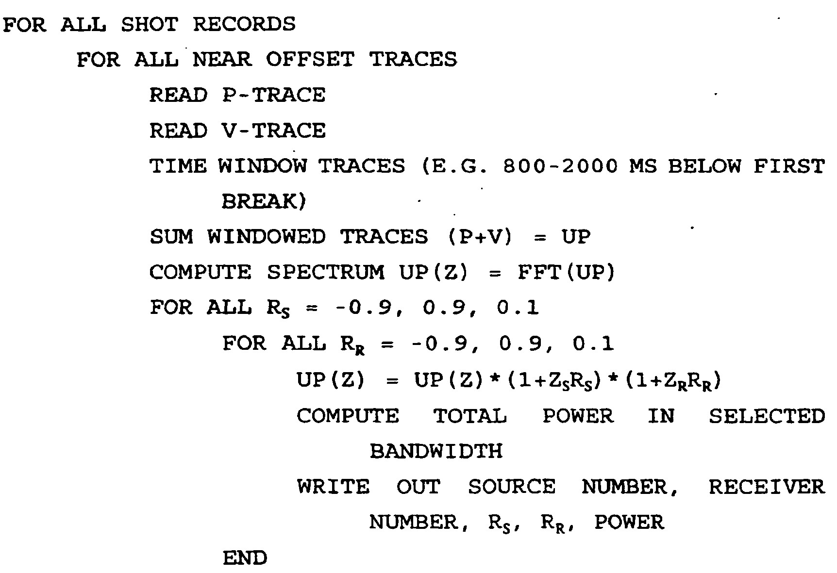
- One preferred implementation of the method involves the following processing sequence:

-
Fig. 3 illustrates a flow diagram which represents a preferred method of determining surface consistent water bottom reflectivities at different source and receiver locations. The preferred method illustrated is generally designated by 300. First, inblock 302, a seismic signal is generated at a source location S. Next, inblocks block 302, are obtained at a receiver location R. Next inblocks block 304 and the velocity signal fromblock 306, generating a windowed pressure signal and a windowed velocity signal, respectively. Preferably, the time window, counting from the first break appearing on each signal, is in the range of 0.8 to 2.0 seconds. Next, inblock 312, the windowed pressure signal fromblock 308 and the windowed velocity signal fromblock 310 are summed to generate a summed signal representing the up-going energy signal, as described in Eq. (1). Then, inblock 314, the summed signal fromblock 312 is transformed from the time domain to the frequency domain, preferably by applying a Fourier transform to the summed signal, generating a transformed signal. Next, inblocks blocks block 322, the inverse split Backus filter from block 320 is multiplied by the transformed signal, generating a filtered signal. - Next, an optimization algorithm is applied to the filtered signal from
block 322 to determine the values of RS and RR. A preferred method of optimization is to minimize the power of the filtered signal fromblock 322. Inblock 324, the power of the filtered signal is computed in a selected frequency band. Preferably, the frequency band is the range from 15 to 80 Hertz. Inblock 326, the values of RS and RR are determined which minimize the total power of the filtered signal in the selected frequency band fromblock 324. Inblock 328, the values of RS and RR fromblock 326 are stored for the current source location S and receiver location R. Then the program logic loops back to read the traces for the next combination of source location S and receiver location R. In blocks 330 and 332, after traces for all the pairs of source and receiver locations are processed, the values of water bottom reflectivities RS and RR are averaged at each source location S and at each receiver location R. - An alternative embodiment of the present invention uses a surface consistent spectral decomposition of the trace spectra into source and receiver components. The decomposed spectra are then analyzed to estimate the water bottom reflectivities at the corresponding source and receiver locations. The spectrum of a seismic trace generated by a source at location n and recorded by a hydrophone at location m can be written in the frequency domain as the product:
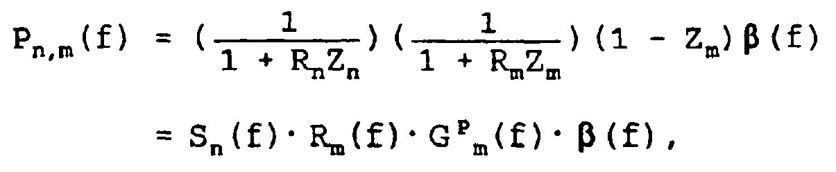
- Zn = the delay operator for a two-way travel time in the water layer at source location n,
- Zm = the delay operator for a two-way travel time in the water layer at receiver location m,
- Rn = the water bottom reflectivity at the source location n,
- Rm = the water bottom reflectivity at the receiver location m, and
- β(f) = the earth reflectivity sequence and the source wavelet.
- Similarly, the spectrum of each geophone trace recorded at location m can be written as:


- Summing the pressure and velocity traces gives the up-going wavefield, which can be written:

- The objective is to extract the source and receiver peg-leg terms from the up-going wavefields. Let NR be the number of receiver locations and NS be the number of source locations, or shots. There is one equation for each trace representing a source-receiver pair, therefore the number of equations is the product NR*NS. There are NR unknown reflectivity values Rm, and NS unknown reflectivity values Rn, so that the total number of unknowns is the sum NR + NS. Thus the number of equations is generally larger than the number of unknowns, so the set of equations can be solved in a least squares sense.
- If the natural logarithm is taken, the equations assume the form:

- Once the amplitude spectrum of Eq. (4) is decomposed into source and receiver components, the water bottom reflectivities need to be extracted from the source and receiver spectra, respectively. Let the delay operators Zn and Zm for the two-way travel time in the water layer at source location n and receiver location m, respectively, be given by


- ω = 2πf,
- τn = two-way travel time at source location n, and
- τm = two-way travel time at receiver location m.
-
Fig. 4 illustrates a flow diagram which represents the alternative embodiment of determining surface consistent water bottom reflectivities at different source and receiver locations. The alternative embodiment illustrated is generally designated by 400. First, inblock 402, seismic waves are generated at NS source locations n. Next, inblocks block 402 are detected at NR receiver locations m by co-located pairs of hydrophones and geophones, generating corresponding pressure and velocity signals, respectively. Next, inblock 408, the pairs of pressure and velocity signals fromblocks block 410, the summed signals fromblock 408 are transformed from the time domain to the frequency domain, preferably by applying a Fourier transform to the summed signals, generating transformed signals. Inblock 412, the transformed signals fromblock 410 are decomposed into source and receiver components. Next, inblock 414, the NS water bottom reflectivities Rn at source locations n and NR water bottom reflectivities Rm at receiver locations m are extracted from the source and receiver components fromblock 412 by an optimization process. Finally, inblocks block 414 are averaged at each source location n and at each receiver location m. - A preferred and an alternative embodiment of the present invention to estimate the water bottom reflectivities from production seismic data in a surface consistent way have been described. This allows the generation of a water bottom reflectivity map in the survey area which can subsequently be used to eliminate source and receiver side water column reverberations by deterministic deconvolution.
- The analysis following Eq. (1) above indicates a method for attenuating the peg-leg multiple sequence. This method is shown in the flow diagram of
Fig. 5 . The method illustrated is generally designated by 500. First, inblock 502, a seismic wave is generated at a source location S. Next, inblocks block 502 are detected at a receiver location R. Inblock 508, the pressure and velocity signals ofblocks block 510, the summed signal ofblock 508 is transformed from the time domain to the frequency domain, preferably by applying a Fourier transform to the summed signal, generating a transformed signal. In blocks 512 and 514, values of water bottom reflectivity RS at the source location S and water bottom reflectivity RR at the receiver location R are determined by appropriate means. Inblock 516, the inverse split Backus filter (1+ZSKS) (1+ZRRR) is computed for the determined water bottom reflectivity values RS and RR fromblocks block 518, the inverse split Backus filter ofblock 516 is multiplied with the transformed signal fromblock 510, generating a filtered signal. Finally, inblock 520, the filtered signal fromblock 518 is transformed from the frequency domain to the time domain, preferably by applying an inverse Fourier transform to the filtered signal. - The present invention has been described with a certain degree of specificity. Variations will occur to those skilled in the art which are within the scope of the invention.


Claims (13)
- A method for determining surface consistent water bottom reflectivities from dual sensor seismic data, comprising the steps of:combining pressure signals and velocity signals to generate combined signals, said combined signals having signal components representing downwardly-travelling energy substantially removed, said pressure and velocity signals corresponding to seismic waves generated at each of at least one source location n in a water layer and detected by co-located pressure and velocity receivers at each of at least one receiver location m in said water layer, said combined signals corresponding to each pairing of source location n and receiver location m;transforming said combined signals from a time domain to a frequency domain, to generate transformed signals;calculating an inverse split Backus filter for each of said transformed signals, and multiplying each of said transformed signals by a corresponding inverse split Backus filter to generate filtered signals; andapplying an optimization algorithm to said filtered signals to determine said water bottom reflectivity values Rn and Rm at said each of at least one source location n and said each of at least one receiver location m, respectively.
- The method of claim 1, wherein said calculating step comprises the steps of:calculating inverse split Backus filters (1+Rn Zn) (1+Rm Zm) in the frequency domain for each of said transformed signals, where Rn and Rm are water bottom reflectivities at said each of at least one source location n and said each of at least one receiver location m, respectively, and Zn and Zm are Z-transforms of a two-way travel time delay filter in said water layer at each said source location n and each said receiver location m, respectively; andmultiplying each of said transformed signals by said corresponding inverse split Backus filter to generate said filtered signals.
- The method of claim 2, wherein said applying an optimization algorithm step comprises the steps of:squaring amplitudes of a frequency spectrum of each of said filtered signals to generate squared signals;summing said squared signals to generate powers;repeating said calculating, multiplying, squaring and summing steps, using different values for said water bottom reflectivities Rn and Rm; anddetermining values for said water bottom reflectivities Rn and Rm which yield the lowest value for said power.
- The method of claim 3, wherein said determining values step is accomplished by selecting values of Rn and Rm within a possible range of values.
- The method of claim 3, wherein the summing step is performed in a restricted frequency band.
- The method of claim 5, wherein said restricted frequency band is a frequency range of 15 to 80 Hertz.
- The method of claim 1, further comprising the steps of:generating averaged water bottom reflectivities by averaging said determined values Rn for said water bottom reflectivities at said each of at least one source location n; andaveraging said determined values Rm for said water bottom reflectivities at said each of at least one receiver position m.
- The method of claim 7, further comprising the step of:using said averaged water bottom reflectivities to generate a surface consistent map of water bottom reflectivities.
- The method of claim 1, further comprising the steps of:applying a time window to each of said pressure signals to generate the pressure signals for combining; andapplying said time window to each of said velocity signals to generate the velocity signals for combining.
- The method of claim 9, further comprising the steps of:determining a first occurrence time for first break of each of said pressure signals;determining a second occurrence time for first break of each of said velocity signals; andplacing said time window after said first occurrence time and said second occurrence time.
- The method of claim 10, wherein said time window is in a range of 0.8 to 2.5 seconds after said first and second occurrence times.
- The method of claim 1, wherein said calculating step comprises the step of:spectrally decomposing said transformed signals to generate a source peg-leg term and a receiver peg-leg term.
- A method as claimed in any one of claims 1 to 12, further comprising the steps of:generating seismic waves in at least one source location n in a water layer;detecting water pressure in at least one receiver location m in said water layer and generating pressure signals indicative of said water pressure; anddetecting water velocity at locations substantially near each said receiver location m in said water layer and generating velocity signals indicative of said water velocities.
Applications Claiming Priority (2)
| Application Number | Priority Date | Filing Date | Title |
|---|---|---|---|
| US08/871,505 US6021092A (en) | 1997-06-09 | 1997-06-09 | Method for deriving surface consistent reflectivity map from dual sensor seismic data |
| US871505 | 1997-06-09 |
Publications (3)
| Publication Number | Publication Date |
|---|---|
| EP0884608A2 EP0884608A2 (en) | 1998-12-16 |
| EP0884608A3 EP0884608A3 (en) | 2001-09-26 |
| EP0884608B1 true EP0884608B1 (en) | 2008-12-31 |
Family
ID=25357598
Family Applications (1)
| Application Number | Title | Priority Date | Filing Date |
|---|---|---|---|
| EP98304431A Expired - Lifetime EP0884608B1 (en) | 1997-06-09 | 1998-06-04 | Seismic surveying |
Country Status (7)
| Country | Link |
|---|---|
| US (1) | US6021092A (en) |
| EP (1) | EP0884608B1 (en) |
| AU (1) | AU725845B2 (en) |
| CA (1) | CA2239851A1 (en) |
| DE (1) | DE69840394D1 (en) |
| ID (1) | ID20815A (en) |
| NO (1) | NO319270B1 (en) |
Cited By (1)
| Publication number | Priority date | Publication date | Assignee | Title |
|---|---|---|---|---|
| WO2013080128A1 (en) * | 2011-11-28 | 2013-06-06 | Geco Technology B.V. | Separation of simultaneous source data |
Families Citing this family (14)
| Publication number | Priority date | Publication date | Assignee | Title |
|---|---|---|---|---|
| CN1120377C (en) * | 2000-04-26 | 2003-09-03 | 西安石油勘探仪器总厂 | Drawn submarine four-component integral earthquake data collecting unit |
| US6833851B1 (en) | 2000-06-06 | 2004-12-21 | Garmin Corporation | GPS Receiver and depth sounder unit having an adjustable display screen |
| GB0015810D0 (en) | 2000-06-29 | 2000-08-23 | Geco As | A method of processing seismic data |
| US20030088372A1 (en) * | 2001-11-02 | 2003-05-08 | Caulfield David D | Array calibration and quality assurance |
| GB2384053B (en) * | 2002-01-11 | 2005-09-14 | Westerngeco Ltd | A method of and apparatus for processing seismic data |
| US7525873B1 (en) * | 2004-07-23 | 2009-04-28 | Bf Corporation North America Inc. | Seismic inversion of conditioned amplitude spectra |
| US7466625B2 (en) * | 2006-06-23 | 2008-12-16 | Westerngeco L.L.C. | Noise estimation in a vector sensing streamer |
| US8593907B2 (en) * | 2007-03-08 | 2013-11-26 | Westerngeco L.L.C. | Technique and system to cancel noise from measurements obtained from a multi-component streamer |
| US7797110B2 (en) * | 2007-06-26 | 2010-09-14 | Shin's Geophysics | Method for velocity analysis using waveform inversion in Laplace domain for geophysical imaging |
| US8451687B2 (en) * | 2009-02-06 | 2013-05-28 | Westerngeco L.L.C. | Imaging with vector measurements |
| US9285493B2 (en) | 2009-08-27 | 2016-03-15 | Pgs Geophysical As | Sensor grouping for dual sensor marine seismic streamer and method for seismic surveying |
| WO2012160430A2 (en) * | 2011-05-24 | 2012-11-29 | Geco Technology B.V. | Data acquisition |
| US10429530B2 (en) * | 2013-04-29 | 2019-10-01 | Westerngeco L.L.C. | Deghosting with adaptive operators |
| US20150338538A1 (en) * | 2014-05-21 | 2015-11-26 | Westerngeco L.L.C. | Multi-model seismic processing operation |
Family Cites Families (4)
| Publication number | Priority date | Publication date | Assignee | Title |
|---|---|---|---|---|
| US5173879A (en) * | 1992-06-25 | 1992-12-22 | Shell Oil Company | Surface-consistent minimum-phase deconvolution |
| US5396472A (en) * | 1993-09-24 | 1995-03-07 | Western Atlas International | Method for deriving water bottom reflectivity in dual sensor seismic surveys |
| US5625150A (en) * | 1994-08-18 | 1997-04-29 | General Electric Company | Integrated acoustic leak detection sensor subsystem |
| US5621700A (en) * | 1996-05-20 | 1997-04-15 | Schlumberger Technology Corporation, Geco-Prakla Div. | Method for attenuation of reverberations using a pressure-velocity bottom cable |
-
1997
- 1997-06-09 US US08/871,505 patent/US6021092A/en not_active Expired - Fee Related
-
1998
- 1998-05-08 NO NO19982093A patent/NO319270B1/en not_active IP Right Cessation
- 1998-06-04 EP EP98304431A patent/EP0884608B1/en not_active Expired - Lifetime
- 1998-06-04 DE DE69840394T patent/DE69840394D1/en not_active Expired - Fee Related
- 1998-06-05 AU AU69944/98A patent/AU725845B2/en not_active Ceased
- 1998-06-08 ID IDP980839A patent/ID20815A/en unknown
- 1998-06-08 CA CA002239851A patent/CA2239851A1/en not_active Abandoned
Cited By (1)
| Publication number | Priority date | Publication date | Assignee | Title |
|---|---|---|---|---|
| WO2013080128A1 (en) * | 2011-11-28 | 2013-06-06 | Geco Technology B.V. | Separation of simultaneous source data |
Also Published As
| Publication number | Publication date |
|---|---|
| NO982093D0 (en) | 1998-05-08 |
| NO319270B1 (en) | 2005-07-11 |
| AU6994498A (en) | 1998-12-10 |
| AU725845B2 (en) | 2000-10-19 |
| DE69840394D1 (en) | 2009-02-12 |
| ID20815A (en) | 1999-03-11 |
| CA2239851A1 (en) | 1998-12-09 |
| US6021092A (en) | 2000-02-01 |
| EP0884608A2 (en) | 1998-12-16 |
| NO982093L (en) | 1998-12-10 |
| EP0884608A3 (en) | 2001-09-26 |
Similar Documents
| Publication | Publication Date | Title |
|---|---|---|
| EP0680616B1 (en) | Method for deriving water bottom reflectivity in dual sensor seismic surveys | |
| EP0534648B1 (en) | Method of marine seismic exploration | |
| EP2177933B1 (en) | Method for Imaging a Sea-Surface Reflector from Towed Dual-Sensor Streamer Data | |
| EP0101281B1 (en) | Underwater seismic testing | |
| US5235554A (en) | Method for correcting impulse response differences of hydrophones and geophones as well as geophone coupling to the water-bottom in dual-sensor, bottom-cable seismic operations | |
| EP2108980B1 (en) | Method for deghosting marine seismic streamer data with irregular receiver positions | |
| CA2273728C (en) | Weighted backus filter method of combining dual sensor traces | |
| US20020118602A1 (en) | Angle dependent surface multiple attenuation for two-component marine bottom sensor data | |
| US5621700A (en) | Method for attenuation of reverberations using a pressure-velocity bottom cable | |
| US5963507A (en) | Method for improving the accuracy of ocean bottom reflectivity estimations using the inverse backus filter | |
| US5309360A (en) | Method for attenuating undesirable data, such as multiples, using constrained cross-equalization | |
| US6021092A (en) | Method for deriving surface consistent reflectivity map from dual sensor seismic data | |
| CA2225504C (en) | Method for measuring the water bottom reflectivity | |
| US20080144435A1 (en) | Deep low frequency towed-array marine survey | |
| US6246637B1 (en) | Method and system for combining three component seismic data | |
| GB2375606A (en) | Angle dependent surface multiple attenuation for two - component marine bottom sensor data |
Legal Events
| Date | Code | Title | Description |
|---|---|---|---|
| PUAI | Public reference made under article 153(3) epc to a published international application that has entered the european phase |
Free format text: ORIGINAL CODE: 0009012 |
|
| AK | Designated contracting states |
Kind code of ref document: A2 Designated state(s): AT BE CH CY DE DK ES FI FR GB GR IE IT LI LU MC NL PT SE Kind code of ref document: A2 Designated state(s): DE FR GB IT NL |
|
| AX | Request for extension of the european patent |
Free format text: AL;LT;LV;MK;RO;SI |
|
| PUAL | Search report despatched |
Free format text: ORIGINAL CODE: 0009013 |
|
| AK | Designated contracting states |
Kind code of ref document: A3 Designated state(s): AT BE CH CY DE DK ES FI FR GB GR IE IT LI LU MC NL PT SE |
|
| AX | Request for extension of the european patent |
Free format text: AL;LT;LV;MK;RO;SI |
|
| 17P | Request for examination filed |
Effective date: 20020218 |
|
| AKX | Designation fees paid |
Free format text: DE FR GB IT NL |
|
| RAP1 | Party data changed (applicant data changed or rights of an application transferred) |
Owner name: WESTERNGECO SEISMIC HOLDINGS LIMITED |
|
| 17Q | First examination report despatched |
Effective date: 20070823 |
|
| GRAP | Despatch of communication of intention to grant a patent |
Free format text: ORIGINAL CODE: EPIDOSNIGR1 |
|
| GRAS | Grant fee paid |
Free format text: ORIGINAL CODE: EPIDOSNIGR3 |
|
| GRAA | (expected) grant |
Free format text: ORIGINAL CODE: 0009210 |
|
| AK | Designated contracting states |
Kind code of ref document: B1 Designated state(s): DE FR GB IT NL |
|
| REG | Reference to a national code |
Ref country code: GB Ref legal event code: FG4D |
|
| REF | Corresponds to: |
Ref document number: 69840394 Country of ref document: DE Date of ref document: 20090212 Kind code of ref document: P |
|
| PLBE | No opposition filed within time limit |
Free format text: ORIGINAL CODE: 0009261 |
|
| STAA | Information on the status of an ep patent application or granted ep patent |
Free format text: STATUS: NO OPPOSITION FILED WITHIN TIME LIMIT |
|
| 26N | No opposition filed |
Effective date: 20091001 |
|
| PG25 | Lapsed in a contracting state [announced via postgrant information from national office to epo] |
Ref country code: DE Free format text: LAPSE BECAUSE OF NON-PAYMENT OF DUE FEES Effective date: 20100101 |
|
| PGFP | Annual fee paid to national office [announced via postgrant information from national office to epo] |
Ref country code: FR Payment date: 20100709 Year of fee payment: 13 |
|
| PGFP | Annual fee paid to national office [announced via postgrant information from national office to epo] |
Ref country code: NL Payment date: 20100603 Year of fee payment: 13 |
|
| PGFP | Annual fee paid to national office [announced via postgrant information from national office to epo] |
Ref country code: GB Payment date: 20100602 Year of fee payment: 13 |
|
| PG25 | Lapsed in a contracting state [announced via postgrant information from national office to epo] |
Ref country code: IT Free format text: LAPSE BECAUSE OF FAILURE TO SUBMIT A TRANSLATION OF THE DESCRIPTION OR TO PAY THE FEE WITHIN THE PRESCRIBED TIME-LIMIT Effective date: 20081231 |
|
| REG | Reference to a national code |
Ref country code: NL Ref legal event code: V1 Effective date: 20120101 |
|
| GBPC | Gb: european patent ceased through non-payment of renewal fee |
Effective date: 20110604 |
|
| REG | Reference to a national code |
Ref country code: FR Ref legal event code: ST Effective date: 20120229 |
|
| PG25 | Lapsed in a contracting state [announced via postgrant information from national office to epo] |
Ref country code: FR Free format text: LAPSE BECAUSE OF NON-PAYMENT OF DUE FEES Effective date: 20110630 |
|
| PG25 | Lapsed in a contracting state [announced via postgrant information from national office to epo] |
Ref country code: NL Free format text: LAPSE BECAUSE OF NON-PAYMENT OF DUE FEES Effective date: 20120101 |
|
| PG25 | Lapsed in a contracting state [announced via postgrant information from national office to epo] |
Ref country code: GB Free format text: LAPSE BECAUSE OF NON-PAYMENT OF DUE FEES Effective date: 20110604 |