EP0884547B1 - Heating element support for an electric heat treating furnace - Google Patents
Heating element support for an electric heat treating furnace Download PDFInfo
- Publication number
- EP0884547B1 EP0884547B1 EP98303844A EP98303844A EP0884547B1 EP 0884547 B1 EP0884547 B1 EP 0884547B1 EP 98303844 A EP98303844 A EP 98303844A EP 98303844 A EP98303844 A EP 98303844A EP 0884547 B1 EP0884547 B1 EP 0884547B1
- Authority
- EP
- European Patent Office
- Prior art keywords
- bracket
- support arm
- heating element
- support
- ceramic sleeve
- Prior art date
- Legal status (The legal status is an assumption and is not a legal conclusion. Google has not performed a legal analysis and makes no representation as to the accuracy of the status listed.)
- Expired - Lifetime
Links
- 238000010438 heat treatment Methods 0.000 title claims description 57
- 239000000919 ceramic Substances 0.000 claims description 50
- 238000005485 electric heating Methods 0.000 claims description 15
- 125000006850 spacer group Chemical group 0.000 claims description 10
- 230000000717 retained effect Effects 0.000 claims 2
- 230000001419 dependent effect Effects 0.000 claims 1
- OKTJSMMVPCPJKN-UHFFFAOYSA-N Carbon Chemical compound [C] OKTJSMMVPCPJKN-UHFFFAOYSA-N 0.000 description 9
- 229910002804 graphite Inorganic materials 0.000 description 9
- 239000010439 graphite Substances 0.000 description 9
- 229910052751 metal Inorganic materials 0.000 description 8
- 239000002184 metal Substances 0.000 description 8
- 238000011109 contamination Methods 0.000 description 3
- 238000001465 metallisation Methods 0.000 description 3
- ZOKXTWBITQBERF-UHFFFAOYSA-N Molybdenum Chemical compound [Mo] ZOKXTWBITQBERF-UHFFFAOYSA-N 0.000 description 2
- 229910010293 ceramic material Inorganic materials 0.000 description 2
- 238000001816 cooling Methods 0.000 description 2
- 239000000463 material Substances 0.000 description 2
- 150000002739 metals Chemical class 0.000 description 2
- 238000012986 modification Methods 0.000 description 2
- 230000004048 modification Effects 0.000 description 2
- 229910052750 molybdenum Inorganic materials 0.000 description 2
- 239000011733 molybdenum Substances 0.000 description 2
- 229910000851 Alloy steel Inorganic materials 0.000 description 1
- 238000005299 abrasion Methods 0.000 description 1
- 229910045601 alloy Inorganic materials 0.000 description 1
- 239000000956 alloy Substances 0.000 description 1
- PNEYBMLMFCGWSK-UHFFFAOYSA-N aluminium oxide Inorganic materials [O-2].[O-2].[O-2].[Al+3].[Al+3] PNEYBMLMFCGWSK-UHFFFAOYSA-N 0.000 description 1
- 238000005336 cracking Methods 0.000 description 1
- 238000009434 installation Methods 0.000 description 1
- 238000012423 maintenance Methods 0.000 description 1
- 230000000750 progressive effect Effects 0.000 description 1
- 230000035939 shock Effects 0.000 description 1
- 238000005382 thermal cycling Methods 0.000 description 1
- 238000003466 welding Methods 0.000 description 1
Images


Classifications
-
- H—ELECTRICITY
- H05—ELECTRIC TECHNIQUES NOT OTHERWISE PROVIDED FOR
- H05B—ELECTRIC HEATING; ELECTRIC LIGHT SOURCES NOT OTHERWISE PROVIDED FOR; CIRCUIT ARRANGEMENTS FOR ELECTRIC LIGHT SOURCES, IN GENERAL
- H05B3/00—Ohmic-resistance heating
- H05B3/62—Heating elements specially adapted for furnaces
- H05B3/66—Supports or mountings for heaters on or in the wall or roof
-
- F—MECHANICAL ENGINEERING; LIGHTING; HEATING; WEAPONS; BLASTING
- F27—FURNACES; KILNS; OVENS; RETORTS
- F27D—DETAILS OR ACCESSORIES OF FURNACES, KILNS, OVENS OR RETORTS, IN SO FAR AS THEY ARE OF KINDS OCCURRING IN MORE THAN ONE KIND OF FURNACE
- F27D1/00—Casings; Linings; Walls; Roofs
- F27D1/0003—Linings or walls
- F27D1/0036—Linings or walls comprising means for supporting electric resistances in the furnace
Definitions
- This invention relates to electric furnaces for the heat treating of metals, and in particular, to a support or hanger for the electric heating elements used in such furnaces.
- Electric heat treating furnaces utilize electric heating elements formed of molybdenum or graphite as radiant heat sources.
- the electric heating elements are usually arrayed circumferentially around the hot zone of the furnace.
- the electric heating elements are supported from the furnace wall by hangers or support members which are attached to the furnace wall at one end and which include hardware for attaching the heating element thereto at their other end.
- the heating element support includes electrical insulating components so that the heating element is electrically isolated from the portion of the element support that is attached to the furnace wall.
- the electrical insulating components are usually formed of a ceramic material. Over time, during repeated operation of the furnace, the surface of the ceramic components becomes contaminated from materials that are dropped on them or by progressive metallization. Such contamination leads to electrical short circuits that interrupt furnace operation and can cause damage.
- the ceramic insulating components are subject to high stress from thermal shock which can cause cracking and failure of the component.
- the ceramic insulating components are in direct contact with the heating element and are subject to stresses when the heating element expands or contracts during heating and cooling cycles.
- heating element supports on the bottom or hot zone floor of a furnace can be struck by falling parts or tools, which cause the ceramic components to crack or break.
- heating element supports include a support shaft that threads into the wall of the hot zone or furnace.
- Such a heating element support is subject to distortion and galling from thermal cycling in the furnace. That distortion and galling causes the threaded portion of the stand-off to seize, which makes the heating element support very difficult to remove when it must be repaired or replaced.
- a support for an electric heating element includes a support arm having first and second end portions.
- First and second ceramic sleeves extend transversely through the support arm and a bracket surrounds at least three sides of the support arm.
- the bracket is dimensioned and positioned to engage with, and thereby support, the electric heating element.
- the bracket has a transverse interior dimension that is greater than the lengths of the first and second ceramic sleeves, respectively.
- a pair of first ceramic spacers are disposed annularly on said first ceramic sleeve and a pair of second ceramic spacers are disposed annularly on said second ceramic sleeve.
- the ceramic spacers are positioned between the bracket and the support arm to prevent contact between the support arm and the bracket.
- a pin is disposed within each of the first and second ceramic sleeves. The pins extend through the bracket to support and retain the ceramic sleeves, the ceramic spacers, and the bracket on the support arm. Clips are provided for retaining the pins within the ceramic sleeves and the bracket. In this arrangement, the heating element bears on the metallic bracket and does not cause wear or damage to the ceramic elements.
- the bracket also provides a shield against contamination and metallization of the ceramic components.
- the heating element support includes a cap disposed over the first end portion of the support arm and a portion of the bracket adjacent thereto.
- the inboard retaining pin also extends through the cap for to support and retain the cap on the bracket and support arm.
- the cap provides a shield for the ceramic components, particularly those that are disposed along the floor or bottom of the furnace hot zone.
- the heating element support includes a socket adapted to be affixed to a wall of the heat treating furnace.
- the socket is formed for receiving and engaging with the second end portion of the support arm so that the heating element support can be mounted in the electric heat treating furnace.
- the support arm has a notch formed transversely in the second end portion and the socket includes a pin or other means for engaging with the notch to retain the support arm in the socket. Engagement is accomplished by inserting and twisting the support arm in the socket.
- the heating element 10 has an opening 11 formed therein for receiving a heater element support 12.
- the heater element support 12 includes an elongated bar member 14 which has an inboard end portion 16 and an outboard end portion 18.
- bar member 14 has a generally rectangular cross section.
- a U-shaped bracket 20 surrounds the inboard end portion of bar member 14 on at least three sides thereof.
- the U-shaped bracket 20 includes a pair of opposing sidewalls 21a and 21b, and a top portion 22 extending between the sidewalls.
- the opening 11 is oversized relative to the cross-sectional area of the bracket 20 to permit easy fit up when the heating element 10 is assembled to the support 12. The oversized nature of the opening 11 also allows for some expansion of bracket 20 during operation of the heat treating furnace at elevated temperature.
- a cap 23 having a U-shaped portion 24 and flange portions 26a and 26b is mounted on the inboard end of bar member 14.
- the U-shaped portion 24 overlaps a portion of bracket 20 adjacent the inboard end portion 16 of bar member 14 to close off the open end of bracket 20.
- the flange portions 26a and 26b of cap 23 are positioned and oriented to abut the electric heating element 10 on the inboard surface thereof.
- Ceramic sleeves 28a and 28b extend through holes formed in bar member 14.
- the length of the ceramic sleeves 28a, 28b is slightly less than the transverse internal dimension of bracket 20 so that they do not interfere with the assembly of the bracket 20 onto bar member 14.
- a pair of ceramic spacers 32a, 32b are disposed annularly on ceramic sleeve 28a on opposite sides of bar member 14.
- ceramic spacers 32c and 32d are disposed annularly on ceramic sleeve 28b on opposite sides of bar member 14. The ceramic spacers 32a, 32b, 32c, and 32d are thus situated between bar member 14 and the sidewalls 21a and 21b of bracket 20 to prevent contact therebetween.
- a metallic pin 34a is disposed in ceramic sleeve 28a and extends outwardly through holes in the sidewalls of bracket 20 and in the U-shaped portion 24 of cap 23.
- a second metallic pin 34b is disposed in ceramic sleeve 28b and extends through holes in the sidewalls of bracket 20.
- the ends of metallic pins 34a and 34b extend a distance beyond the sidewalls of bracket 20. In the case of pin 34a, the extra length ensures that cap 23 is secured to the bracket 20 thereby preventing the heating element 10 from slipping off of bracket 20.
- Retaining clips 40a, 40b, and 40c, 40d are inserted through holes formed in the metallic pins 34a, 34b, respectively, outboard of the sidewalls 21a, 21b of bracket 20 to prevent the metallic pins 34a, 34b from sliding out of the ceramic sleeves 28a, 28b and bracket 20.
- the flanges 26a and 26b of cap 23 are positioned between metallic pin 34a and the heating element 10 to help retain the heating element 10 on the support 12 and to prevent galling or abrasion of the heating element by pin 34a.
- a washer 46 is slidably disposed around the U-shaped bracket 20 outboard of heating element 10.
- the electric heating element is realized by a metallic strip or band.
- some electric heat treating furnaces utilize graphite bars for the heating elements.
- the metallic pins 34a and 34b are spaced apart by a distance sufficient to permit a graphite bar heating element to fit therebetween.
- the washer 46 abuts the outboard surface of the graphite bar heating element to keep it in place on the support 12 and to prevent abrasive wear of the graphite heating element by pin 34b.
- a socket 48 is provided for attaching the heater element support 12 to a wall of the electric heat treating furnace.
- the socket 48 consists of a cylindrical metallic piece having a central opening 49 for receiving end portion 18 of bar member 14.
- a pin 50 or other means such as a rib, lip, or key, is disposed transversely in the socket member 48 for engaging with a transverse notch 52 formed in the outboard end portion of bar member 14.
- the socket 48 is attached to the furnace wall preferably by welding thereto.
- the heater element support 12 is mounted in the furnace by inserting the outboard end 18 into the central opening 49 of socket 48 and then rotating bar member 14 until the notch 52 engages with pin 50.
- the heater element support 12 is easily removed by reversing the installation operation. This arrangement is highly resistant to seizing.
- the heater element support 12 can be adapted to function as a retainer for the heat shielding.
- a second washer (not shown) is disposed around the bar member 14 inboard of the heat shield liner.
- a hole 54 is formed transversely through the bar member 14 for receiving a retaining clip or wire to hold the retaining washer against the heat shield material.
- the metallic components of the heating element support described hereinabove are formed of a metal or alloy that resists distortion when exposed to the elevated temperatures used to heat treat steel alloys and other metals.
- the metal components such as bar member 14, bracket 20, cap 23, and pins 34a, 34b are formed of molybdenum.
- the ceramic elements are formed of a strong, heat resisting grade of ceramic material such as high alumina.
- a novel heating element support which includes a metal bracket that interfaces with the electric heating element so that the heating element does not bear directly on any ceramic components.
- the bracket 20 and cap 23 are constructed and arranged on the heating element support 12 to minimize contamination or metallization of the surface of the ceramic components that can result in a short circuit between the heating element 10 and the support bar 14.
- the bracket 20 and cap 23 are also effective to shield the ceramic components from parts, tools, or other objects that can damage the ceramic parts.
- the disclosed heating element support is easy to replace because only a single clip and pin must be removed to disassemble the support from the heating element and the entire support is removed from or installed in the furnace with a simple 1 ⁇ 4-turn motion.
- the heating element support according to the present invention is universal in that it is adaptable for use with metal heating elements as well as graphite bar heating elements.
Landscapes
- Engineering & Computer Science (AREA)
- Mechanical Engineering (AREA)
- General Engineering & Computer Science (AREA)
- Furnace Details (AREA)
- Resistance Heating (AREA)
Description
- This invention relates to electric furnaces for the heat treating of metals, and in particular, to a support or hanger for the electric heating elements used in such furnaces.
- Electric heat treating furnaces utilize electric heating elements formed of molybdenum or graphite as radiant heat sources. The electric heating elements are usually arrayed circumferentially around the hot zone of the furnace. U.S. Patent Nos. 5,502,742; 4,612,651; 4,559,631; and 3,812,276, the disclosures of which are incorporated herein by reference, show and describe typical arrangements of heat treating furnaces having electric heating elements .
- In the known furnaces, the electric heating elements are supported from the furnace wall by hangers or support members which are attached to the furnace wall at one end and which include hardware for attaching the heating element thereto at their other end. Typically, the heating element support includes electrical insulating components so that the heating element is electrically isolated from the portion of the element support that is attached to the furnace wall. The electrical insulating components are usually formed of a ceramic material. Over time, during repeated operation of the furnace, the surface of the ceramic components becomes contaminated from materials that are dropped on them or by progressive metallization. Such contamination leads to electrical short circuits that interrupt furnace operation and can cause damage.
- In electric heat treating furnaces that include forced gas cooling systems, the ceramic insulating components are subject to high stress from thermal shock which can cause cracking and failure of the component. In the furnaces, the ceramic insulating components are in direct contact with the heating element and are subject to stresses when the heating element expands or contracts during heating and cooling cycles. Furthermore, during furnace operation or maintenance, heating element supports on the bottom or hot zone floor of a furnace can be struck by falling parts or tools, which cause the ceramic components to crack or break.
- Many of the known heating element supports include a support shaft that threads into the wall of the hot zone or furnace. Such a heating element support is subject to distortion and galling from thermal cycling in the furnace. That distortion and galling causes the threaded portion of the stand-off to seize, which makes the heating element support very difficult to remove when it must be repaired or replaced.
- Another drawback to the known heating element supports is that they must be specifically designed for either graphite or metal heating elements because a graphite heating element is significantly thicker than a metal heating element.
- In view of the foregoing, it would be highly desirable to have a support for an electric heating element in an electric heat treating furnace which overcomes the disadvantages of the known heating element supports.
- The disadvantages associated with the known furnace heating element supports are resolved to a large degree by a heating element support in accordance with the present invention. A support for an electric heating element according to this invention includes a support arm having first and second end portions. First and second ceramic sleeves extend transversely through the support arm and a bracket surrounds at least three sides of the support arm. The bracket is dimensioned and positioned to engage with, and thereby support, the electric heating element. The bracket has a transverse interior dimension that is greater than the lengths of the first and second ceramic sleeves, respectively. A pair of first ceramic spacers are disposed annularly on said first ceramic sleeve and a pair of second ceramic spacers are disposed annularly on said second ceramic sleeve. The ceramic spacers are positioned between the bracket and the support arm to prevent contact between the support arm and the bracket. A pin is disposed within each of the first and second ceramic sleeves. The pins extend through the bracket to support and retain the ceramic sleeves, the ceramic spacers, and the bracket on the support arm. Clips are provided for retaining the pins within the ceramic sleeves and the bracket. In this arrangement, the heating element bears on the metallic bracket and does not cause wear or damage to the ceramic elements. The bracket also provides a shield against contamination and metallization of the ceramic components.
- In accordance with another aspect of the present invention, the heating element support includes a cap disposed over the first end portion of the support arm and a portion of the bracket adjacent thereto. The inboard retaining pin also extends through the cap for to support and retain the cap on the bracket and support arm. The cap provides a shield for the ceramic components, particularly those that are disposed along the floor or bottom of the furnace hot zone.
- In accordance with a further aspect of this invention the heating element support includes a socket adapted to be affixed to a wall of the heat treating furnace. The socket is formed for receiving and engaging with the second end portion of the support arm so that the heating element support can be mounted in the electric heat treating furnace. In this arrangement, the support arm has a notch formed transversely in the second end portion and the socket includes a pin or other means for engaging with the notch to retain the support arm in the socket. Engagement is accomplished by inserting and twisting the support arm in the socket.
- The foregoing summary as well as the following detailed description of a preferred embodiment of the present invention will be better understood when read in conjunction with the appended drawings, wherein:
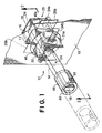
- Figure 1 is a perspective view of an electric heating element and a support therefor in accordance with the present invention;
- Figure 2 is a bottom plan view of the heating element support shown in Figure 1, as viewed along line 2-2 therein;
- Figure 3 is a side elevation view in partial section of the heating element support shown in Figure 2, as viewed along line 3-3 therein; and
- Figure 4 is a front elevation view of the heating element support shown in Figure 1.
-
- Referring now to the drawings wherein like reference numerals refer to the same components across the several views, there is shown a portion of an
electric heating element 10 of the type used in an electric heat treating furnace. Theheating element 10 has an opening 11 formed therein for receiving aheater element support 12. Theheater element support 12 includes anelongated bar member 14 which has aninboard end portion 16 and anoutboard end portion 18. In the embodiment shown in the drawing figures,bar member 14 has a generally rectangular cross section. A U-shapedbracket 20 surrounds the inboard end portion ofbar member 14 on at least three sides thereof. The U-shapedbracket 20 includes a pair ofopposing sidewalls top portion 22 extending between the sidewalls. The opening 11 is oversized relative to the cross-sectional area of thebracket 20 to permit easy fit up when theheating element 10 is assembled to thesupport 12. The oversized nature of the opening 11 also allows for some expansion ofbracket 20 during operation of the heat treating furnace at elevated temperature. - A
cap 23 having aU-shaped portion 24 andflange portions bar member 14. The U-shapedportion 24 overlaps a portion ofbracket 20 adjacent theinboard end portion 16 ofbar member 14 to close off the open end ofbracket 20. Theflange portions cap 23 are positioned and oriented to abut theelectric heating element 10 on the inboard surface thereof. -
Ceramic sleeves bar member 14. The length of theceramic sleeves bracket 20 so that they do not interfere with the assembly of thebracket 20 ontobar member 14. A pair ofceramic spacers ceramic sleeve 28a on opposite sides ofbar member 14. In like manner,ceramic spacers ceramic sleeve 28b on opposite sides ofbar member 14. Theceramic spacers bar member 14 and thesidewalls bracket 20 to prevent contact therebetween. - A
metallic pin 34a is disposed inceramic sleeve 28a and extends outwardly through holes in the sidewalls ofbracket 20 and in the U-shapedportion 24 ofcap 23. In like manner, a secondmetallic pin 34b is disposed inceramic sleeve 28b and extends through holes in the sidewalls ofbracket 20. The ends ofmetallic pins bracket 20. In the case ofpin 34a, the extra length ensures thatcap 23 is secured to thebracket 20 thereby preventing theheating element 10 from slipping off ofbracket 20. Retainingclips metallic pins sidewalls bracket 20 to prevent themetallic pins ceramic sleeves bracket 20. Theflanges cap 23 are positioned betweenmetallic pin 34a and theheating element 10 to help retain theheating element 10 on thesupport 12 and to prevent galling or abrasion of the heating element bypin 34a. - A
washer 46 is slidably disposed around theU-shaped bracket 20 outboard ofheating element 10. In the embodiment shown in the drawings, the electric heating element is realized by a metallic strip or band. However, as noted above, some electric heat treating furnaces utilize graphite bars for the heating elements. The metallic pins 34a and 34b are spaced apart by a distance sufficient to permit a graphite bar heating element to fit therebetween. When a graphite bar heating element is used, thewasher 46 abuts the outboard surface of the graphite bar heating element to keep it in place on thesupport 12 and to prevent abrasive wear of the graphite heating element bypin 34b. - A
socket 48 is provided for attaching theheater element support 12 to a wall of the electric heat treating furnace. In the embodiment shown in the drawing figures, thesocket 48 consists of a cylindrical metallic piece having acentral opening 49 for receivingend portion 18 ofbar member 14. Apin 50 or other means such as a rib, lip, or key, is disposed transversely in thesocket member 48 for engaging with atransverse notch 52 formed in the outboard end portion ofbar member 14. Thesocket 48 is attached to the furnace wall preferably by welding thereto. Theheater element support 12 is mounted in the furnace by inserting theoutboard end 18 into thecentral opening 49 ofsocket 48 and then rotatingbar member 14 until thenotch 52 engages withpin 50. Theheater element support 12 is easily removed by reversing the installation operation. This arrangement is highly resistant to seizing. - In an electric furnace that has heat shielding around the hot zone, the
heater element support 12 can be adapted to function as a retainer for the heat shielding. In this regard a second washer (not shown) is disposed around thebar member 14 inboard of the heat shield liner. Ahole 54 is formed transversely through thebar member 14 for receiving a retaining clip or wire to hold the retaining washer against the heat shield material. - The metallic components of the heating element support described hereinabove are formed of a metal or alloy that resists distortion when exposed to the elevated temperatures used to heat treat steel alloys and other metals. Preferably, the metal components such as
bar member 14,bracket 20,cap 23, and pins 34a, 34b are formed of molybdenum. The ceramic elements are formed of a strong, heat resisting grade of ceramic material such as high alumina. - In view of the foregoing disclosure, some of the many novel features and advantages of the present invention are now apparent. For example, a novel heating element support has been described which includes a metal bracket that interfaces with the electric heating element so that the heating element does not bear directly on any ceramic components. The
bracket 20 andcap 23 are constructed and arranged on theheating element support 12 to minimize contamination or metallization of the surface of the ceramic components that can result in a short circuit between theheating element 10 and thesupport bar 14. Thebracket 20 andcap 23 are also effective to shield the ceramic components from parts, tools, or other objects that can damage the ceramic parts. The disclosed heating element support is easy to replace because only a single clip and pin must be removed to disassemble the support from the heating element and the entire support is removed from or installed in the furnace with a simple ¼-turn motion. Moreover, the heating element support according to the present invention is universal in that it is adaptable for use with metal heating elements as well as graphite bar heating elements. - It will be recognized by those skilled in the art that changes or modifications may be made to the above-described invention without departing from the broad inventive concepts of this invention. It is understood, therefore, that the invention is not limited to the particular embodiments disclosed herein, but is intended to cover all modifications and changes which are within the scope of the invention as defined in the appended claims.
Claims (12)
- A support (12) for an electric heating element (10) in an electric heat treating furnace comprising:a support arm (14) having first and second end portions (16 and 18);a bracket (20) surrounding the first end portion (16) of said support arm, said bracket having at least three sides (21a, 21b, 22);electrically insulating elements (28a-b, 32a-d) disposed between said support arm (14) and said bracket (20) such that said support arm (14) is electrically isolated from said bracket (20); andmeans (34a-b, 40a-d) for retaining said bracket (20) on said support arm (14) and for retaining said electrically insulating elements (32a-d) between said support arm (14) and said bracket (20).
- A heating element support (12) according to claim 1, comprising a cap (23) disposed over the first end portion (16) of said support arm (14) and a portion of said bracket (20) that is adjacent thereto, said cap (23) being retained on said support arm (14) and said bracket (20) by said retaining means (34a, 40a-b).
- A heating element support (12) according to claim 1 or 2, wherein said insulating elements comprisea first ceramic sleeve (28a) extending transversely through said support arm (14); anda pair of first ceramic spacers (32a, 32b) disposed annularly on said first ceramic sleeve (28a) and on opposite sides of said support arm (14) so as to prevent contact between said support arm (14) and said bracket (20).
- A heating element support (12) according to claim 3, wherein said retaining means (34a) is disposed through said first ceramic sleeve (28a) and extends through two opposing sides (21a, 21b) of said bracket (20).
- A heating element support (12) according to claim 3, wherein said insulating elements further comprise a second ceramic sleeve (28b) disposed transversely through said support arm (14) and spaced apart from said first ceramic sleeve (28a); and
a pair of second ceramic spacers (32c, 32d) disposed annularly on said second ceramic sleeve (28b) and on opposite sides of said support arm (14) so as to prevent contact between said support arm (14) and said bracket (20). - A heating element support (12) according to claim 1 or 2, wherein said retaining means comprises at least one pin (34a, 34b) extending through opposing sides (21a, 21b) of said bracket (20), through said insulating elements (28a-b,32a-d), and through said support arm (14).
- A heating element support (12) according to claim 5, wherein said retaining means comprises a first pin (34a) extending through the opposing sides (21a, 21b) of said bracket (20) and through said first ceramic sleeve (28a) and a second pin (34b) extending through the opposing sides (21a,21b) of said bracket (20) and through said second ceramic sleeve (28b).
- A heating element support (12) according to any one of the preceding claims, comprising a socket (48) for fixing to a wall of the electric heat treating furnace to receive and engage with the second end portion (18) of said support arm (14) to enable the heater element support to be mounted in the electric heat treating furnace.
- A heating element support (12) according to claim 8, wherein said support arm (14) has a notch (52) formed transversely in the second end portion (18) and said socket (48) includes means (50) for engaging with said notch (52) for retaining the support arm (14) in said socket (48).
- A heating element support (12) according to claim 7, or claim 8 or 9 when dependent on claim 7, comprising a washer (46) slidably disposed around said bracket (20) between said first and second pins (34a, 34b).
- An electric heat treating furnace provided with a heating element support (12) according to any one of the preceding claims.
- A support (12) for an electric heating element (10) in an electric heat treating furnace comprising:a support arm (14) having first and second end portions (16 and 18);a first ceramic sleeve (28a) extending transversely through said support arm (14);a bracket (20) surrounding at least three sides of said support arm (14) and having a transverse interior dimension that is greater than the length of said first ceramic sleeve (28a);a pair of first ceramic spacers (32a,32b) disposed annularly on said first ceramic sleeve (28a) between said support arm (14) and said bracket (20) so as to prevent contact between said support arm and said bracket;a pin (34a) disposed within said ceramic sleeve (28a) and extending through said bracket (20), whereby said first ceramic sleeve (28a) and said bracket (20) are supported and retained on said support arm (14), andmeans (40a,b) for retaining said pin within said first ceramic sleeve (28a) and said bracket (20).
Applications Claiming Priority (2)
| Application Number | Priority Date | Filing Date | Title |
|---|---|---|---|
| US858496 | 1997-05-19 | ||
| US08/858,496 US5930285A (en) | 1997-05-19 | 1997-05-19 | Heating element support for an electric heat treating furnace |
Publications (2)
| Publication Number | Publication Date |
|---|---|
| EP0884547A1 EP0884547A1 (en) | 1998-12-16 |
| EP0884547B1 true EP0884547B1 (en) | 2002-10-30 |
Family
ID=25328452
Family Applications (1)
| Application Number | Title | Priority Date | Filing Date |
|---|---|---|---|
| EP98303844A Expired - Lifetime EP0884547B1 (en) | 1997-05-19 | 1998-05-15 | Heating element support for an electric heat treating furnace |
Country Status (4)
| Country | Link |
|---|---|
| US (1) | US5930285A (en) |
| EP (1) | EP0884547B1 (en) |
| CA (1) | CA2238119C (en) |
| DE (1) | DE69808992T2 (en) |
Families Citing this family (5)
| Publication number | Priority date | Publication date | Assignee | Title |
|---|---|---|---|---|
| SE9603965D0 (en) * | 1996-10-30 | 1996-10-30 | Kanthal Ab | Electric furnace assembly |
| US6111908A (en) * | 1999-08-16 | 2000-08-29 | Jones; William R. | High temperature vacuum heater supporting mechanism with cup shaped shield |
| DE10257907B4 (en) * | 2002-12-11 | 2011-09-29 | Snap-On Equipment Gmbh | Method and apparatus for checking the uniformity of a pneumatic tire |
| US9702627B2 (en) | 2014-05-16 | 2017-07-11 | William R. Jones | High temperature vacuum furnace heater element support assembly |
| US20170074589A1 (en) | 2015-09-11 | 2017-03-16 | Ipsen Inc. | System and Method for Facilitating the Maintenance of an Industrial Furnace |
Family Cites Families (12)
| Publication number | Priority date | Publication date | Assignee | Title |
|---|---|---|---|---|
| US3456935A (en) * | 1967-09-20 | 1969-07-22 | Alco Standard Corp | Heat treating furnace with shielding packs |
| US3737553A (en) * | 1971-12-09 | 1973-06-05 | Abar Corp | Vacuum electric furnace |
| US3812276A (en) * | 1973-07-05 | 1974-05-21 | Abar Corp | Resistance heating element for vacuum furnaces |
| US4056678A (en) * | 1976-02-20 | 1977-11-01 | Sola Basic Industries, Inc. | Electric heating furnace |
| US4156792A (en) * | 1977-09-14 | 1979-05-29 | Bickley Furnaces Incorporated | Electric furnace construction |
| SE413453B (en) * | 1978-08-30 | 1980-05-27 | Bulten Kanthal Ab | HALL ROW FOR ELECTRIC RESISTANCE ELEMENTS IN OVEN |
| US4259538A (en) * | 1980-01-31 | 1981-03-31 | Jones William R | Vacuum furnace arrangement having an improved heating element mounting means |
| US4612651A (en) * | 1984-05-24 | 1986-09-16 | Abar Ipsen Industries | Heat treating furnace with heating element hangers and radiation shield spacers |
| US4559631A (en) * | 1984-09-14 | 1985-12-17 | Abar Ipsen Industries | Heat treating furnace with graphite heating elements |
| US4860306A (en) * | 1988-10-05 | 1989-08-22 | Vacuum Furnace Systems Corporation | Hot zone employing graphite heating elements |
| PL170386B1 (en) * | 1993-01-14 | 1996-12-31 | Seco Warwick Sp Z Oo | Vacuum-type heat treatment furnace |
| US5502742A (en) * | 1993-02-26 | 1996-03-26 | Abar Ipsen Industries, Inc. | Heat treating furnace with removable floor, adjustable heating element support, and threaded ceramic gas injection nozzle |
-
1997
- 1997-05-19 US US08/858,496 patent/US5930285A/en not_active Expired - Lifetime
-
1998
- 1998-05-15 DE DE69808992T patent/DE69808992T2/en not_active Expired - Fee Related
- 1998-05-15 EP EP98303844A patent/EP0884547B1/en not_active Expired - Lifetime
- 1998-05-15 CA CA002238119A patent/CA2238119C/en not_active Expired - Lifetime
Also Published As
| Publication number | Publication date |
|---|---|
| DE69808992T2 (en) | 2003-06-18 |
| CA2238119C (en) | 2003-11-25 |
| EP0884547A1 (en) | 1998-12-16 |
| US5930285A (en) | 1999-07-27 |
| DE69808992D1 (en) | 2002-12-05 |
| CA2238119A1 (en) | 1998-11-19 |
Similar Documents
| Publication | Publication Date | Title |
|---|---|---|
| JPH0739859B2 (en) | Support structure ceramic heat shield | |
| US4259538A (en) | Vacuum furnace arrangement having an improved heating element mounting means | |
| CA2238119C (en) | Heating element support for an electric heat treating furnace | |
| KR0125093B1 (en) | Molten Aluminum Support Device | |
| US4635172A (en) | Recessed lighting fixture having thermal protection | |
| ATE241705T1 (en) | HEAT TREATMENT SYSTEM FOR A BATCH OF METALLIC WORKPIECES | |
| JP4331901B2 (en) | Ceramic susceptor support structure | |
| US6167602B1 (en) | Lamp removal tool | |
| EP0306459B1 (en) | Temperature detecting apparatus for pipes in refinery furnaces and the like | |
| GB2043369A (en) | Lamp holder | |
| BR9805689A (en) | Structural member of the furnace body for metallurgical cupola furnace. | |
| US4468783A (en) | Electrode for arc furnaces | |
| US4860306A (en) | Hot zone employing graphite heating elements | |
| US5153480A (en) | Vibration, shock and heat-resistant lamp-base combination structure | |
| NZ198753A (en) | Arc furnace electrode:mouldings protect cooling ducts | |
| US4932187A (en) | Refractory anchor system and method | |
| EP3586076B1 (en) | Cooling panel for metallurgical furnace | |
| AU6601698A (en) | Shield for molten metal immersible thermocouple support pole | |
| US2922017A (en) | Electric heating element and support | |
| JP3579932B2 (en) | Panel heater | |
| RU2845889C2 (en) | Holder, heater and method | |
| EP0066986A1 (en) | Insulation for a furnace member | |
| KR200142835Y1 (en) | U-bolt/nut for fixing coil pipe | |
| KR100686499B1 (en) | Bushing block mounting frame | |
| KR910009054B1 (en) | Valve plate assembly for sliding gate valve of metallurgy vessel. |
Legal Events
| Date | Code | Title | Description |
|---|---|---|---|
| PUAI | Public reference made under article 153(3) epc to a published international application that has entered the european phase |
Free format text: ORIGINAL CODE: 0009012 |
|
| AK | Designated contracting states |
Kind code of ref document: A1 Designated state(s): DE FR GB IT |
|
| AX | Request for extension of the european patent |
Free format text: AL;LT;LV;MK;RO;SI |
|
| 17P | Request for examination filed |
Effective date: 19990517 |
|
| AKX | Designation fees paid |
Free format text: DE FR GB IT |
|
| GRAG | Despatch of communication of intention to grant |
Free format text: ORIGINAL CODE: EPIDOS AGRA |
|
| 17Q | First examination report despatched |
Effective date: 20020204 |
|
| GRAG | Despatch of communication of intention to grant |
Free format text: ORIGINAL CODE: EPIDOS AGRA |
|
| GRAH | Despatch of communication of intention to grant a patent |
Free format text: ORIGINAL CODE: EPIDOS IGRA |
|
| GRAH | Despatch of communication of intention to grant a patent |
Free format text: ORIGINAL CODE: EPIDOS IGRA |
|
| GRAA | (expected) grant |
Free format text: ORIGINAL CODE: 0009210 |
|
| AK | Designated contracting states |
Kind code of ref document: B1 Designated state(s): DE FR GB IT |
|
| REG | Reference to a national code |
Ref country code: GB Ref legal event code: FG4D |
|
| REF | Corresponds to: |
Ref document number: 69808992 Country of ref document: DE Date of ref document: 20021205 |
|
| PGFP | Annual fee paid to national office [announced via postgrant information from national office to epo] |
Ref country code: FR Payment date: 20030428 Year of fee payment: 6 |
|
| ET | Fr: translation filed | ||
| PGFP | Annual fee paid to national office [announced via postgrant information from national office to epo] |
Ref country code: DE Payment date: 20030730 Year of fee payment: 6 |
|
| PLBE | No opposition filed within time limit |
Free format text: ORIGINAL CODE: 0009261 |
|
| STAA | Information on the status of an ep patent application or granted ep patent |
Free format text: STATUS: NO OPPOSITION FILED WITHIN TIME LIMIT |
|
| 26N | No opposition filed |
Effective date: 20030731 |
|
| PGFP | Annual fee paid to national office [announced via postgrant information from national office to epo] |
Ref country code: GB Payment date: 20040519 Year of fee payment: 7 |
|
| PG25 | Lapsed in a contracting state [announced via postgrant information from national office to epo] |
Ref country code: DE Free format text: LAPSE BECAUSE OF NON-PAYMENT OF DUE FEES Effective date: 20041201 |
|
| PG25 | Lapsed in a contracting state [announced via postgrant information from national office to epo] |
Ref country code: FR Free format text: LAPSE BECAUSE OF NON-PAYMENT OF DUE FEES Effective date: 20050131 |
|
| REG | Reference to a national code |
Ref country code: FR Ref legal event code: ST |
|
| PG25 | Lapsed in a contracting state [announced via postgrant information from national office to epo] |
Ref country code: IT Free format text: LAPSE BECAUSE OF NON-PAYMENT OF DUE FEES Effective date: 20050515 Ref country code: GB Free format text: LAPSE BECAUSE OF NON-PAYMENT OF DUE FEES Effective date: 20050515 |
|
| GBPC | Gb: european patent ceased through non-payment of renewal fee |
Effective date: 20050515 |