EP0884079A1 - Selfcleaning filter - Google Patents
Selfcleaning filter Download PDFInfo
- Publication number
- EP0884079A1 EP0884079A1 EP97830286A EP97830286A EP0884079A1 EP 0884079 A1 EP0884079 A1 EP 0884079A1 EP 97830286 A EP97830286 A EP 97830286A EP 97830286 A EP97830286 A EP 97830286A EP 0884079 A1 EP0884079 A1 EP 0884079A1
- Authority
- EP
- European Patent Office
- Prior art keywords
- filter
- helix
- shaped bar
- scraping
- filtering element
- Prior art date
- Legal status (The legal status is an assumption and is not a legal conclusion. Google has not performed a legal analysis and makes no representation as to the accuracy of the status listed.)
- Withdrawn
Links
- 238000001914 filtration Methods 0.000 claims abstract description 55
- 238000007790 scraping Methods 0.000 claims abstract description 36
- 238000004140 cleaning Methods 0.000 claims abstract description 26
- 239000000463 material Substances 0.000 claims description 8
- 239000012530 fluid Substances 0.000 claims description 6
- 238000006073 displacement reaction Methods 0.000 claims description 3
- 238000004804 winding Methods 0.000 claims description 3
- 239000007787 solid Substances 0.000 description 10
- 230000000694 effects Effects 0.000 description 7
- 238000000034 method Methods 0.000 description 7
- 238000005406 washing Methods 0.000 description 7
- 239000007788 liquid Substances 0.000 description 4
- 230000002829 reductive effect Effects 0.000 description 4
- 238000010276 construction Methods 0.000 description 3
- 238000009434 installation Methods 0.000 description 3
- 238000004519 manufacturing process Methods 0.000 description 3
- CDBYLPFSWZWCQE-UHFFFAOYSA-L Sodium Carbonate Chemical compound [Na+].[Na+].[O-]C([O-])=O CDBYLPFSWZWCQE-UHFFFAOYSA-L 0.000 description 2
- 229910000831 Steel Inorganic materials 0.000 description 2
- 230000009471 action Effects 0.000 description 2
- 150000001875 compounds Chemical class 0.000 description 2
- 230000008878 coupling Effects 0.000 description 2
- 238000010168 coupling process Methods 0.000 description 2
- 238000005859 coupling reaction Methods 0.000 description 2
- 239000011796 hollow space material Substances 0.000 description 2
- 230000036961 partial effect Effects 0.000 description 2
- 230000000284 resting effect Effects 0.000 description 2
- 230000000717 retained effect Effects 0.000 description 2
- 239000010959 steel Substances 0.000 description 2
- BVKZGUZCCUSVTD-UHFFFAOYSA-M Bicarbonate Chemical class OC([O-])=O BVKZGUZCCUSVTD-UHFFFAOYSA-M 0.000 description 1
- 229910000639 Spring steel Inorganic materials 0.000 description 1
- 230000035508 accumulation Effects 0.000 description 1
- 238000009825 accumulation Methods 0.000 description 1
- 238000005054 agglomeration Methods 0.000 description 1
- 230000004931 aggregating effect Effects 0.000 description 1
- 230000002776 aggregation Effects 0.000 description 1
- 230000002547 anomalous effect Effects 0.000 description 1
- 150000004649 carbonic acid derivatives Chemical class 0.000 description 1
- 239000000701 coagulant Substances 0.000 description 1
- 239000011247 coating layer Substances 0.000 description 1
- 238000007598 dipping method Methods 0.000 description 1
- 230000006872 improvement Effects 0.000 description 1
- 230000002427 irreversible effect Effects 0.000 description 1
- 230000014759 maintenance of location Effects 0.000 description 1
- 230000004048 modification Effects 0.000 description 1
- 238000012986 modification Methods 0.000 description 1
- 239000002245 particle Substances 0.000 description 1
- 238000005192 partition Methods 0.000 description 1
- 230000035515 penetration Effects 0.000 description 1
- 239000004033 plastic Substances 0.000 description 1
- 229920000867 polyelectrolyte Polymers 0.000 description 1
- 230000008569 process Effects 0.000 description 1
- 230000000750 progressive effect Effects 0.000 description 1
- 230000002035 prolonged effect Effects 0.000 description 1
- 230000009467 reduction Effects 0.000 description 1
- 229910000029 sodium carbonate Inorganic materials 0.000 description 1
- 235000017550 sodium carbonate Nutrition 0.000 description 1
- 229910001220 stainless steel Inorganic materials 0.000 description 1
- 239000010935 stainless steel Substances 0.000 description 1
- 238000003860 storage Methods 0.000 description 1
- 239000004753 textile Substances 0.000 description 1
- 238000009941 weaving Methods 0.000 description 1
Images

Classifications
-
- B—PERFORMING OPERATIONS; TRANSPORTING
- B01—PHYSICAL OR CHEMICAL PROCESSES OR APPARATUS IN GENERAL
- B01D—SEPARATION
- B01D29/00—Filters with filtering elements stationary during filtration, e.g. pressure or suction filters, not covered by groups B01D24/00 - B01D27/00; Filtering elements therefor
- B01D29/11—Filters with filtering elements stationary during filtration, e.g. pressure or suction filters, not covered by groups B01D24/00 - B01D27/00; Filtering elements therefor with bag, cage, hose, tube, sleeve or like filtering elements
- B01D29/117—Filters with filtering elements stationary during filtration, e.g. pressure or suction filters, not covered by groups B01D24/00 - B01D27/00; Filtering elements therefor with bag, cage, hose, tube, sleeve or like filtering elements arranged for outward flow filtration
- B01D29/118—Filters with filtering elements stationary during filtration, e.g. pressure or suction filters, not covered by groups B01D24/00 - B01D27/00; Filtering elements therefor with bag, cage, hose, tube, sleeve or like filtering elements arranged for outward flow filtration open-ended
-
- B—PERFORMING OPERATIONS; TRANSPORTING
- B01—PHYSICAL OR CHEMICAL PROCESSES OR APPARATUS IN GENERAL
- B01D—SEPARATION
- B01D29/00—Filters with filtering elements stationary during filtration, e.g. pressure or suction filters, not covered by groups B01D24/00 - B01D27/00; Filtering elements therefor
- B01D29/62—Regenerating the filter material in the filter
- B01D29/64—Regenerating the filter material in the filter by scrapers, brushes, nozzles, or the like, acting on the cake side of the filtering element
- B01D29/6469—Regenerating the filter material in the filter by scrapers, brushes, nozzles, or the like, acting on the cake side of the filtering element scrapers
- B01D29/6476—Regenerating the filter material in the filter by scrapers, brushes, nozzles, or the like, acting on the cake side of the filtering element scrapers with a rotary movement with respect to the filtering element
Definitions
- the present invention relates to a self-cleaning filter.
- a known technical solution for restricting areas subjected to said clogging and reduce discharge and washing frequency consists in increasing the filter element surface so as to enable a constant flowing even when a 30-40% clogging occurs.
- filters of the self-cleaning type are provided with devices capable of periodically carrying out an at least partial removal of deposits.
- self-cleaning filters have devices which are active on the inner surface of the filtering elements in which, if filters providing flowing from inside to outside are involved, the amount of the material that can be accumulated is the greatest, so that a serious clogging may occur.
- a first known technique is based on the use of scraping blades mounted on the rotating shaft disposed internally of the filtering element and resting on the inner cylindrical surface of said filtering element.
- this technique is efficient in a great number of applications, it has proved to be inappropriate in particular installations and above all when suspended solids of the filamentary or thread-like type are concerned, which happens in weaving for example.
- deposits of the filamentary nature are hardly removed and partly remain on the inner surface of the filtering element thereby creating agglomerated masses that, by progressively closing the passage area, give rise to an irreversible increase in the loss of head through the filter.
- filamentary deposits tend to get entangled on the rotating blade-carrier shaft, thereby giving rise to further problems in terms of loss of efficiency of the filter.
- rotating blades consisting of steel wires, but although said blades increase the cleaning effect in that wires achieve a deep penetration into the filtering element slits, which effect is impossible with blades having a continuous profile, they do not avoid suspended solids being retained in said wires which in the progress of time will give rise to accumulations that will decrease both efficiency of the cleaning action and the free passage areas in the filtering elements.
- Another known technique is based on the use of suitably bored pistons to enable dipping into the fluid, which pistons are driven with a reciprocating motion internally of the filtering element and are peripherally provided with rings made of rubber or other material and slidable against the inner surface of the filtering element itself.
- Improvement in the cleaning efficiency of the piston may be achieved by driving the latter in rotation during its translational motion by means of a nut screw coupling.
- the technical task underlying the present invention is to devise a self-cleaning filter capable of substantially obviating the above drawbacks.
- Another important object of the invention is to devise a self-cleaning filter of simple construction, reduced production costs and easy assembling.
- the self-cleaning filter in accordance with the invention is generally identified by reference numeral 1.
- the filtering element 2 comprises a filtering element 2, of tubular form, having a main filtering surface 2a, herein the inner one, typically of cylindrical conformation, although it is not limited to this shape.
- the filtering element 2 is set internally of a cylindrical casing 3 provided with an inlet opening 4 disposed uppermost and an outlet opening 5 disposed lowermost.
- an inner partition 6 is provided which is centrally pierced with a hole and with which an upper end 2a of the filtering element 2 is engaged so that the liquid to be submitted to filtration may flow from the inside to the outside of the filtering element itself 2 into a hollow space 7 interposed between said filtering element and casing 3.
- the liquid flow from the inlet opening 4 may be provided to move radially from the outside to the inside.
- the main surface 2a of the filtering element will be the radially outer one.
- the filtering element 2 at the lower portion thereof rests on a bottom 8 of casing 3 and opens into a discharge duct 9 for evacuation of the removed deposits which is provided with an appropriate discharge valve (not shown in the figures) to be driven to its open and closed positions following predetermined time intervals or when predetermined pressure differences between the inlet opening 4 and outlet opening 5 are reached.
- the self-cleaning filter 1 further comprises a device for cleaning the filtering element 2 consisting of a scraping element 10 having, in an original manner, a helical conformation, and of movement means 11 adapted to set the scraping element 10 in rotation about its central axis 12 substantially coincident with the longitudinal extension axis of the main surface 2a.
- the scraping element 10 is defined by a bar of spring material, preferably spring stainless steel conveniently wound into helical turns 10a of a shape matching that of the main surface 2a and having a scraping edge 10b disposed in contact with the main surface of the filtering element 2.
- the scraping element too would consist of a cylindrical helix housed within the filtering element 2 (see figures).
- the main surface 2a be coincident with the radially outer surface of the filtering element 2 for example, the scraping element would be a helix operating in the hollow space 7 and active externally of element 2.
- the helix-shaped bar 10 has a substantially square transverse section disposed in a manner adapted to cause abutment of two corners 10c and 10d of the scraping edge 10b against the cylindrical surface 2a.
- the movement means 11 in addition to comprising a motor 13 and a shaft 14, is also provided with an attachment unit 15 which is integral with one drive end 10e of the helix-shaped bar 10 disposed uppermost.
- Unit 15 consists of a disc 15a and a counter-disc 15b adapted to sandwich and lock said drive end 10e therebetween.
- turns 10a have such a winding direction and the bar is moved according to such a rotation direction about the central axis 12 that displacements from top to bottom of the scraping edge 10b are caused.
- the winding direction of turns 10a is to the left, the rotation direction of shaft 14 and helix-shaped bar 10 seen from the top is clockwise.
- the helix-shaped bar 10 has some turns, two or three turns close to the drive end 10 for example, disposed externally of the filtering element 2.
- the helix-shaped bar 10 in a working position that is when it is set within the filtering element, has a preloading in a torsional direction originating a spring thrust towards the cylindrical surface itself 2a.
- the helix-shaped bar 10 material at least at the scraping edge 10b, has a surface hardness lower than that of the cylindrical surface 2a, so as to preserve the most expensive component, i.e. the filtering element 2, and therefore carry out replacement due to wear of the scraping element 10 alone.
- the helix-shaped scraping element 10 by rotating about the central axis 12, simultaneously carries out both downward displacement of the solid deposits resting on the inner cylindrical surface 2a and removal of same from the filtering element slits by means of a component extending oblique to said slits, which component is adapted to cause a particularly efficient tear-detaching effect in the case of deposits of the filamentary type.
- Movement of the scraping element 2 and opening of the underlying discharge valve can be arranged either at predetermined time intervals for given time lengths, or on reaching of a predetermined pressure difference between the inlet 4 and outlet 5 openings.
- the scraping element 10 When important amounts of solids are suspended in the fluid to be filtered, the scraping element 10 can be maintained in permanent rotation and opening and closing of the discharge valve can be timed, so that a constant cleaning of the filtering element 2 can be maintained, which avoids variations in the loss of head.
- an outer counter-washing unit may be associated with the helix-shaped scraping element 10 carrying out internal cleaning, which unit is particularly appropriate to remove solids when they are jammed in the hollow spaces between the filtering bars, above all when compounds having a crystallizing effect are being retained such as soda ash, bicarbonates, carbonates and aggregating compounds, i.e. polyelectrolytes and coagulating agents.
- Counter washing is carried out by means of nozzles oriented tangentially of the outer surface of the filtering element and disposed at diametrically opposite positions to obtain a whirl effect.
- the motor and scraping element are set in rotation when counter-washing is performed, whereas the discharge valve may have a continuous or timed operation.
- the invention achieves important advantages.
- the helix conformation of the scraping element and engagement of said element with the movement means only at one end thereof enable a free passage to be obtained over the whole path of travel from the inlet opening of the filter to the inner surface of the filtering element, without any obstacle being disposed centrally and with reduction of the free filtering area only as much as strictly necessary. Therefore anomalous agglomerations and deposit retentions cannot occur along said path. The related loss of head is also greatly reduced.
- the square-section conformation of the scraping element enables availability of two side-by-side scraping lines which will double the cleaning effect and increase efficiency of the filtering element above all in case of big amounts of filamentary deposits.
- the helix-shaped scraping element is a component of reduced cost, which can be easily replaced and offers a limited friction against the filtering element, so that also consumption of the absorbed energy for movement of same is of a reduced amount.
Landscapes
- Chemical & Material Sciences (AREA)
- Chemical Kinetics & Catalysis (AREA)
- Filtration Of Liquid (AREA)
Abstract
A self-cleaning filter (1) is provided which comprises a
tubular filtering element (2), a scraping element (10) of
helical conformation disposed within the filtering
element, and movement means (11) adapted to set the
scraping element in rotation.
Description
The present invention relates to a self-cleaning filter.
It is known that in some industrial processes, in the
textile and paper fields for example, solid particles
suspended in the fluids submitted to filtration can reach
very important amounts for each square metre of said
fluids, thereby giving rise to a progressive clogging
over the whole surface of the filtering elements, which
will force users to carry out frequent discharge and
washing operations to the detriment of an inexpensive
production.
A known technical solution for restricting areas
subjected to said clogging and reduce discharge and
washing frequency consists in increasing the filter
element surface so as to enable a constant flowing even
when a 30-40% clogging occurs.
However, this solution has the serious drawback that
installation of oversize filters relative to the actual
process requirements is needed and therefore economically
unbearable costs are involved.
Therefore, generally use of filters of the self-cleaning
type is preferred. Said filters are provided with devices
capable of periodically carrying out an at least partial
removal of deposits. In more detail, self-cleaning
filters have devices which are active on the inner
surface of the filtering elements in which, if filters
providing flowing from inside to outside are involved,
the amount of the material that can be accumulated is the
greatest, so that a serious clogging may occur.
There is a great variety of known techniques for carrying
out self-cleaning filters.
A first known technique is based on the use of scraping
blades mounted on the rotating shaft disposed internally
of the filtering element and resting on the inner
cylindrical surface of said filtering element. Although
this technique is efficient in a great number of
applications, it has proved to be inappropriate in
particular installations and above all when suspended
solids of the filamentary or thread-like type are
concerned, which happens in weaving for example.
Actually, deposits of the filamentary nature are hardly
removed and partly remain on the inner surface of the
filtering element thereby creating agglomerated masses
that, by progressively closing the passage area, give
rise to an irreversible increase in the loss of head
through the filter.
In addition, filamentary deposits tend to get entangled
on the rotating blade-carrier shaft, thereby giving rise
to further problems in terms of loss of efficiency of the
filter.
Other alternative solutions of known type, based either
on counter-rotation of the filtering element relative to
the scraping blades for example, or on addition of
sucking ducts terminating at the scraping blades, give
rise to a greater construction complexity of the plant
and higher installation and operating costs, while on the
other hand are unable to improve removal of filamentary
solid deposits from the filtering element to an important
extent and to eliminate storing of said deposits on the
supporting portions of the blades.
Also provided are rotating blades consisting of steel
wires, but although said blades increase the cleaning
effect in that wires achieve a deep penetration into the
filtering element slits, which effect is impossible with
blades having a continuous profile, they do not avoid
suspended solids being retained in said wires which in
the progress of time will give rise to accumulations that
will decrease both efficiency of the cleaning action and
the free passage areas in the filtering elements.
If dismantling of these steel wire blades and strong
washing of same is not periodically carried out, blades
themselves are converted into material blocks the their
cleaning effect becomes almost null, which in addition
will bring about possible damages for overloading to the
support shaft and each blade.
Another known technique is based on the use of suitably
bored pistons to enable dipping into the fluid, which
pistons are driven with a reciprocating motion internally
of the filtering element and are peripherally provided
with rings made of rubber or other material and slidable
against the inner surface of the filtering element
itself.
This known technique, also due to the low translation
speed of the piston, can give rise to deposit of
filamentary solids on the shaft and the solid surface of
the piston thereby involving a continuous storage of
material that can cause slowing in the active piston
stroke and even a complete stopping of said piston. In
addition, piston may cause worsening in the cleanness
condition of the filtering element if deposits, instead
of being removed, are pressed against the outer surface
of the filtering element where they form a coating layer,
thereby increasing difficulty in removal.
Improvement in the cleaning efficiency of the piston may
be achieved by driving the latter in rotation during its
translational motion by means of a nut screw coupling.
However, this technical solution does not avoid deposits
on the piston and requires great accuracy in couplings in
addition to appropriate protection of the nut screw
dipped in the liquid, which will greatly increase
construction costs.
Practically the above described known techniques for
obtaining good efficiency and efficacy features in the
filtering action require either periodical dismantling
and washing steps or replacement of the cleaning elements
and filtering elements.
Under this situation, the technical task underlying the
present invention is to devise a self-cleaning filter
capable of substantially obviating the above drawbacks.
Within the scope of this technical task, it is an
important object of the invention to devise a self-cleaning
filter enabling great efficiency and efficacy
features constant in time to be maintained in the
filtering element provided therein, even in the presence
of filamentary solids suspended in the fluids to be
filtered.
Another important object of the invention is to devise a
self-cleaning filter of simple construction, reduced
production costs and easy assembling.
The technical task mentioned and the objects specified
are substantially achieved by a self-cleaning filter as
described in the appended claims.
Description of a preferred but non-exclusive embodiment
of a self-cleaning filter in accordance with the
invention is now given hereinafter, with reference to the
accompanying drawings, in which:
- Fig. 1 is a longitudinal sectional view of a self-cleaning filter in accordance with the invention;
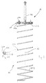
- Fig. 2 shows the cleaning device included in the self-cleaning filter seen in Fig. 1; and
- Fig. 2a shows a detail of Fig. 2 to an enlarged scale.
With reference to the drawings, the self-cleaning filter
in accordance with the invention is generally identified
by reference numeral 1.
It comprises a filtering element 2, of tubular form,
having a main filtering surface 2a, herein the inner one,
typically of cylindrical conformation, although it is not
limited to this shape. The filtering element 2 is set
internally of a cylindrical casing 3 provided with an
inlet opening 4 disposed uppermost and an outlet opening
5 disposed lowermost. In addition, under the inlet
opening 4, an inner partition 6 is provided which is
centrally pierced with a hole and with which an upper end
2a of the filtering element 2 is engaged so that the
liquid to be submitted to filtration may flow from the
inside to the outside of the filtering element itself 2
into a hollow space 7 interposed between said filtering
element and casing 3.
Clearly, by carrying out obvious modifications, the
liquid flow from the inlet opening 4 may be provided to
move radially from the outside to the inside. In the
last-mentioned case, the main surface 2a of the filtering
element will be the radially outer one.
The filtering element 2 at the lower portion thereof
rests on a bottom 8 of casing 3 and opens into a
discharge duct 9 for evacuation of the removed deposits
which is provided with an appropriate discharge valve
(not shown in the figures) to be driven to its open and
closed positions following predetermined time intervals
or when predetermined pressure differences between the
inlet opening 4 and outlet opening 5 are reached.
The self-cleaning filter 1 further comprises a device for
cleaning the filtering element 2 consisting of a scraping
element 10 having, in an original manner, a helical
conformation, and of movement means 11 adapted to set the
scraping element 10 in rotation about its central axis 12
substantially coincident with the longitudinal extension
axis of the main surface 2a.
More specifically, the scraping element 10 is defined by
a bar of spring material, preferably spring stainless
steel conveniently wound into helical turns 10a of a
shape matching that of the main surface 2a and having a
scraping edge 10b disposed in contact with the main
surface of the filtering element 2.
More particularly, should the main surface 2a have a
cylindrical conformation and be coincident with the inner
surface of the filtering element, the scraping element
too would consist of a cylindrical helix housed within
the filtering element 2 (see figures). On the contrary,
should the main surface 2a be coincident with the
radially outer surface of the filtering element 2 for
example, the scraping element would be a helix operating
in the hollow space 7 and active externally of element 2.
Advantageously the helix-shaped bar 10 has a
substantially square transverse section disposed in a
manner adapted to cause abutment of two corners 10c and
10d of the scraping edge 10b against the cylindrical
surface 2a.
The movement means 11, in addition to comprising a motor
13 and a shaft 14, is also provided with an attachment
unit 15 which is integral with one drive end 10e of the
helix-shaped bar 10 disposed uppermost. Unit 15 consists
of a disc 15a and a counter-disc 15b adapted to sandwich
and lock said drive end 10e therebetween.
In the helix-shaped bar 10, turns 10a have such a winding
direction and the bar is moved according to such a
rotation direction about the central axis 12 that
displacements from top to bottom of the scraping edge 10b
are caused. For instance if, as illustrated in the
accompanying figures, the winding direction of turns 10a
is to the left, the rotation direction of shaft 14 and
helix-shaped bar 10 seen from the top is clockwise.
In addition, in order to compensate for possible
misalignments of shaft 14 and helix-shaped bar 10
relative to the filtering element 2, and to enable a free
flowing of the liquid into the filtering element without
obstacles resulting from the presence of the attachment
unit 15, the helix-shaped bar 10 has some turns, two or
three turns close to the drive end 10 for example,
disposed externally of the filtering element 2.
For the purpose of constantly ensuring a spring contact
of the scraping edge 10b against the cylindrical surface
2a of the filtering element 2, the helix-shaped bar 10 in
a working position, that is when it is set within the
filtering element, has a preloading in a torsional
direction originating a spring thrust towards the
cylindrical surface itself 2a.
Finally, the helix-shaped bar 10 material, at least at
the scraping edge 10b, has a surface hardness lower than
that of the cylindrical surface 2a, so as to preserve the
most expensive component, i.e. the filtering element 2,
and therefore carry out replacement due to wear of the
scraping element 10 alone.
Operation of the self-cleaning filter described above
mainly as regards structure, is as follows.
The helix-shaped scraping element 10, by rotating about
the central axis 12, simultaneously carries out both
downward displacement of the solid deposits resting on
the inner cylindrical surface 2a and removal of same from
the filtering element slits by means of a component
extending oblique to said slits, which component is
adapted to cause a particularly efficient tear-detaching
effect in the case of deposits of the filamentary type.
Movement of the scraping element 2 and opening of the
underlying discharge valve can be arranged either at
predetermined time intervals for given time lengths, or
on reaching of a predetermined pressure difference
between the inlet 4 and outlet 5 openings.
When important amounts of solids are suspended in the
fluid to be filtered, the scraping element 10 can be
maintained in permanent rotation and opening and closing
of the discharge valve can be timed, so that a constant
cleaning of the filtering element 2 can be maintained,
which avoids variations in the loss of head.
Advantageously, an outer counter-washing unit, known per
se, may be associated with the helix-shaped scraping
element 10 carrying out internal cleaning, which unit is
particularly appropriate to remove solids when they are
jammed in the hollow spaces between the filtering bars,
above all when compounds having a crystallizing effect
are being retained such as soda ash, bicarbonates,
carbonates and aggregating compounds, i.e.
polyelectrolytes and coagulating agents. Counter washing
is carried out by means of nozzles oriented tangentially
of the outer surface of the filtering element and
disposed at diametrically opposite positions to obtain a
whirl effect. The motor and scraping element are set in
rotation when counter-washing is performed, whereas the
discharge valve may have a continuous or timed operation.
The invention achieves important advantages.
First of all, the helix conformation of the scraping
element and engagement of said element with the movement
means only at one end thereof enable a free passage to be
obtained over the whole path of travel from the inlet
opening of the filter to the inner surface of the
filtering element, without any obstacle being disposed
centrally and with reduction of the free filtering area
only as much as strictly necessary. Therefore anomalous
agglomerations and deposit retentions cannot occur along
said path. The related loss of head is also greatly
reduced.
The square-section conformation of the scraping element
enables availability of two side-by-side scraping lines
which will double the cleaning effect and increase
efficiency of the filtering element above all in case of
big amounts of filamentary deposits.
Use of spring steel for the scraping element, in
opposition to the known art in which plastic material is
employed, in addition to enabling operation at high
temperatures too, in the range of 90-130°C for example,
also allows the scraping element to be constantly and
elastically kept into contact with the filtering element
even after continuous and prolonged operations that may
cause partial wear of the scraping element, which will
reduce necessity for servicing interventions.
Finally, the helix-shaped scraping element is a component
of reduced cost, which can be easily replaced and offers
a limited friction against the filtering element, so that
also consumption of the absorbed energy for movement of
same is of a reduced amount.
Claims (11)
- A self-cleaning filter, comprising:a filtering element of tubular form (2) having a main filtering surface (2a) intended to receive a fluid to be filtered therethrough;at least one scraping element (10) disposed internally of said filtering element (2) and comprising a scraping edge (10b) in contact with said surface (2a), characterized in that said scraping element (10) has a helical conformation the central axis (12) of which is substantially coincident with a longitudinal extension axis of the main surface itself (2a); and in that movement means (11) is provided which is adapted to set said scraping element (10) in rotation about said central axis (12).
- A filter as claimed in claim 1, characterized in that said scraping element (10) is defined by a bar consisting of wound turns (10a) forming a cylindrical or conical helix.
- A filter as claimed in claim 2, characterized in that said movement means (11) comprises an attachment unit (15) integral with one drive end (10e) of said helix-shaped bar.
- A filter as claimed in claim 2, characterized in that said helix-shaped bar (10) has a polygonal, preferably square, transverse section, disposed in a manner adapted to cause abutment of two corners (10c, 10d) of said scraping edge (10b) against said main surface (2a) of said filtering element (2).
- A filter as claimed in claim 3, characterized in that said drive end (10e) of said helix-shaped bar (10) is disposed uppermost.
- A filter as claimed in claim 2, characterized in that in said helix-shaped bar (10) turns 10a have such a winding direction and the bar is moved according to such a rotation direction about said central axis (12) that displacements from top to bottom of said scraping edge (10b) are caused.
- A filter as claimed in claim 5, characterized in that said helix-shaped bar (10) comprises at least one turn (10a) close to said drive end (10e) which is disposed externally of said filtering element (2).
- A filter as claimed in claim 7, characterized in that said attachment unit (15) comprises a disc (15a) and a counter-disc (15b) adapted to sandwich and lock said drive end (10e) of the helix-shaped bar (10) therebetween.
- A filter as claimed in claim 2, characterized in that said helix-shaped bar (10) is made of spring material.
- A filter as claimed in claim 8, characterized in that said helix-shaped bar (10) in a working position within said filtering element (2) has a preloading in a torsional direction adapted to cause spring abutment of the helix-shaped bar itself (10) against said main surface (2a).
- A filter as claimed in claim 1, characterized in that at least said scraping edge (10b) has a surface hardness lower than the surface hardness of said filtering element (2) at said inner cylindrical surface (2a).
Priority Applications (1)
| Application Number | Priority Date | Filing Date | Title |
|---|---|---|---|
| EP97830286A EP0884079A1 (en) | 1997-06-12 | 1997-06-12 | Selfcleaning filter |
Applications Claiming Priority (1)
| Application Number | Priority Date | Filing Date | Title |
|---|---|---|---|
| EP97830286A EP0884079A1 (en) | 1997-06-12 | 1997-06-12 | Selfcleaning filter |
Publications (1)
| Publication Number | Publication Date |
|---|---|
| EP0884079A1 true EP0884079A1 (en) | 1998-12-16 |
Family
ID=8230662
Family Applications (1)
| Application Number | Title | Priority Date | Filing Date |
|---|---|---|---|
| EP97830286A Withdrawn EP0884079A1 (en) | 1997-06-12 | 1997-06-12 | Selfcleaning filter |
Country Status (1)
| Country | Link |
|---|---|
| EP (1) | EP0884079A1 (en) |
Cited By (1)
| Publication number | Priority date | Publication date | Assignee | Title |
|---|---|---|---|---|
| FR2964885A1 (en) * | 2010-09-21 | 2012-03-23 | Paul Helderle | Effluent filtering device for use at outlet of e.g. oil well, has sweeping unit sweeping filtering residues residing on tubular effluent filtering member toward recuperation unit of residues |
Citations (3)
| Publication number | Priority date | Publication date | Assignee | Title |
|---|---|---|---|---|
| FR529099A (en) * | 1918-06-05 | 1921-11-23 | Hermann Plauson | Filter press |
| DE2629848A1 (en) * | 1975-07-02 | 1977-01-20 | Enzo Dr Gervasi | PROCESS FOR FILTERING COAT LIQUIDS AND DEVICE FOR CARRYING OUT THE PROCESS |
| EP0594167A1 (en) * | 1992-10-23 | 1994-04-27 | Hans-Georg Huber | Device for removing separable matter from a liquid flowing in a gutter |
-
1997
- 1997-06-12 EP EP97830286A patent/EP0884079A1/en not_active Withdrawn
Patent Citations (3)
| Publication number | Priority date | Publication date | Assignee | Title |
|---|---|---|---|---|
| FR529099A (en) * | 1918-06-05 | 1921-11-23 | Hermann Plauson | Filter press |
| DE2629848A1 (en) * | 1975-07-02 | 1977-01-20 | Enzo Dr Gervasi | PROCESS FOR FILTERING COAT LIQUIDS AND DEVICE FOR CARRYING OUT THE PROCESS |
| EP0594167A1 (en) * | 1992-10-23 | 1994-04-27 | Hans-Georg Huber | Device for removing separable matter from a liquid flowing in a gutter |
Cited By (1)
| Publication number | Priority date | Publication date | Assignee | Title |
|---|---|---|---|---|
| FR2964885A1 (en) * | 2010-09-21 | 2012-03-23 | Paul Helderle | Effluent filtering device for use at outlet of e.g. oil well, has sweeping unit sweeping filtering residues residing on tubular effluent filtering member toward recuperation unit of residues |
Similar Documents
| Publication | Publication Date | Title |
|---|---|---|
| US4818402A (en) | Self cleaning strainer | |
| US11083985B2 (en) | Vapor relief strainer with cleaner | |
| KR101450017B1 (en) | Device and method for cleaning a filter cloth | |
| EP2767321B1 (en) | Self-cleaning filter | |
| EP0494800A2 (en) | Filter with reciprocating cleaner unit | |
| US20220016552A1 (en) | Slit spiral tube for self-cleaning pressure filters and a slot self-cleaning pressure filter with such a slit tube | |
| CN1636495A (en) | Self-cleaning filters and vacuum cleaners containing self-cleaning filters | |
| EP4124373B1 (en) | Backwash suction device of fibrous filter | |
| US20160310876A1 (en) | Filtration system and filter assembly associated therewith | |
| CN102755774A (en) | Self-cleaning type filter and dyeing machine including same | |
| US5728297A (en) | Apparatus for the mechanical cleaning of liquids | |
| WO2009022019A1 (en) | Pump rotor and pump comprising a pump rotor of said type | |
| EP1785178A1 (en) | Method for cleaning a filtering system and a filtering system having cleaning capabilities. | |
| CN114087764A (en) | Drainage device on dehumidifier and dehumidifier | |
| CN116920490B (en) | Self-cleaning valve and method of use thereof | |
| CN113926233B (en) | A filter that starts at low load | |
| EP2341998B1 (en) | Method and device for cleaning a filter for fluids | |
| CN201988256U (en) | Precision-adjustable disk type filter | |
| USRE34218E (en) | Easily-cleanable filters | |
| CN209575912U (en) | Self-driving type filter | |
| CN208678520U (en) | A kind of self-cleaning filter | |
| CN203139747U (en) | Electric scrapper assembly for self-cleaning filter sieve | |
| RU2630009C1 (en) | Well filter (versions) | |
| SU1165427A1 (en) | Edge filter for liqiud | |
| KR20210106649A (en) | Cloth media disc filtration apparatus |
Legal Events
| Date | Code | Title | Description |
|---|---|---|---|
| PUAI | Public reference made under article 153(3) epc to a published international application that has entered the european phase |
Free format text: ORIGINAL CODE: 0009012 |
|
| AK | Designated contracting states |
Kind code of ref document: A1 Designated state(s): AT BE CH DE ES FR GB IT LI NL SE |
|
| AX | Request for extension of the european patent |
Free format text: AL;LT;LV;RO;SI |
|
| 17P | Request for examination filed |
Effective date: 19981202 |
|
| AKX | Designation fees paid |
Free format text: AT BE CH DE ES FR GB IT LI NL SE |
|
| STAA | Information on the status of an ep patent application or granted ep patent |
Free format text: STATUS: THE APPLICATION IS DEEMED TO BE WITHDRAWN |
|
| 18D | Application deemed to be withdrawn |
Effective date: 20010103 |