EP0883892B1 - Vacuum compatible linear motion device - Google Patents
Vacuum compatible linear motion device Download PDFInfo
- Publication number
- EP0883892B1 EP0883892B1 EP97953082A EP97953082A EP0883892B1 EP 0883892 B1 EP0883892 B1 EP 0883892B1 EP 97953082 A EP97953082 A EP 97953082A EP 97953082 A EP97953082 A EP 97953082A EP 0883892 B1 EP0883892 B1 EP 0883892B1
- Authority
- EP
- European Patent Office
- Prior art keywords
- bearing
- fluid
- collar
- linear motion
- enclosure
- Prior art date
- Legal status (The legal status is an assumption and is not a legal conclusion. Google has not performed a legal analysis and makes no representation as to the accuracy of the status listed.)
- Expired - Lifetime
Links
- 239000012530 fluid Substances 0.000 claims abstract description 74
- 239000000463 material Substances 0.000 claims description 22
- 238000013022 venting Methods 0.000 claims description 20
- 230000008878 coupling Effects 0.000 claims description 14
- 238000010168 coupling process Methods 0.000 claims description 14
- 238000005859 coupling reaction Methods 0.000 claims description 14
- 238000010894 electron beam technology Methods 0.000 claims description 11
- 230000002706 hydrostatic effect Effects 0.000 claims description 10
- 239000004698 Polyethylene Substances 0.000 claims description 5
- 239000004642 Polyimide Substances 0.000 claims description 5
- 230000009977 dual effect Effects 0.000 claims description 5
- 230000005484 gravity Effects 0.000 claims description 5
- 229930195733 hydrocarbon Natural products 0.000 claims description 5
- 150000002430 hydrocarbons Chemical class 0.000 claims description 5
- 239000007788 liquid Substances 0.000 claims description 5
- -1 polyethylene Polymers 0.000 claims description 5
- 229920000573 polyethylene Polymers 0.000 claims description 5
- 229920001721 polyimide Polymers 0.000 claims description 5
- 239000004215 Carbon black (E152) Substances 0.000 claims 3
- 238000005086 pumping Methods 0.000 claims 2
- 229920003223 poly(pyromellitimide-1,4-diphenyl ether) Polymers 0.000 description 5
- 229920006362 Teflon® Polymers 0.000 description 4
- 230000008901 benefit Effects 0.000 description 4
- 238000011109 contamination Methods 0.000 description 4
- 238000000059 patterning Methods 0.000 description 4
- 238000005096 rolling process Methods 0.000 description 4
- 238000013459 approach Methods 0.000 description 3
- 238000004519 manufacturing process Methods 0.000 description 3
- 229910001220 stainless steel Inorganic materials 0.000 description 3
- 239000010935 stainless steel Substances 0.000 description 3
- 230000006835 compression Effects 0.000 description 2
- 238000007906 compression Methods 0.000 description 2
- 230000008030 elimination Effects 0.000 description 2
- 238000003379 elimination reaction Methods 0.000 description 2
- 239000000314 lubricant Substances 0.000 description 2
- 238000005461 lubrication Methods 0.000 description 2
- 238000001393 microlithography Methods 0.000 description 2
- 230000003287 optical effect Effects 0.000 description 2
- 239000004033 plastic Substances 0.000 description 2
- 229920003023 plastic Polymers 0.000 description 2
- 229920000642 polymer Polymers 0.000 description 2
- 239000004065 semiconductor Substances 0.000 description 2
- 238000000926 separation method Methods 0.000 description 2
- 239000004809 Teflon Substances 0.000 description 1
- 238000000429 assembly Methods 0.000 description 1
- 230000000712 assembly Effects 0.000 description 1
- 229910052790 beryllium Inorganic materials 0.000 description 1
- ATBAMAFKBVZNFJ-UHFFFAOYSA-N beryllium atom Chemical compound [Be] ATBAMAFKBVZNFJ-UHFFFAOYSA-N 0.000 description 1
- 238000010276 construction Methods 0.000 description 1
- 230000003670 easy-to-clean Effects 0.000 description 1
- 230000000694 effects Effects 0.000 description 1
- 238000000609 electron-beam lithography Methods 0.000 description 1
- 239000003562 lightweight material Substances 0.000 description 1
- 229910052751 metal Inorganic materials 0.000 description 1
- 239000002184 metal Substances 0.000 description 1
- 238000000034 method Methods 0.000 description 1
- 229920001343 polytetrafluoroethylene Polymers 0.000 description 1
- 239000004810 polytetrafluoroethylene Substances 0.000 description 1
Images



Classifications
-
- F—MECHANICAL ENGINEERING; LIGHTING; HEATING; WEAPONS; BLASTING
- F16—ENGINEERING ELEMENTS AND UNITS; GENERAL MEASURES FOR PRODUCING AND MAINTAINING EFFECTIVE FUNCTIONING OF MACHINES OR INSTALLATIONS; THERMAL INSULATION IN GENERAL
- F16C—SHAFTS; FLEXIBLE SHAFTS; ELEMENTS OR CRANKSHAFT MECHANISMS; ROTARY BODIES OTHER THAN GEARING ELEMENTS; BEARINGS
- F16C32/00—Bearings not otherwise provided for
- F16C32/06—Bearings not otherwise provided for with moving member supported by a fluid cushion formed, at least to a large extent, otherwise than by movement of the shaft, e.g. hydrostatic air-cushion bearings
-
- F—MECHANICAL ENGINEERING; LIGHTING; HEATING; WEAPONS; BLASTING
- F16—ENGINEERING ELEMENTS AND UNITS; GENERAL MEASURES FOR PRODUCING AND MAINTAINING EFFECTIVE FUNCTIONING OF MACHINES OR INSTALLATIONS; THERMAL INSULATION IN GENERAL
- F16C—SHAFTS; FLEXIBLE SHAFTS; ELEMENTS OR CRANKSHAFT MECHANISMS; ROTARY BODIES OTHER THAN GEARING ELEMENTS; BEARINGS
- F16C29/00—Bearings for parts moving only linearly
- F16C29/02—Sliding-contact bearings
- F16C29/025—Hydrostatic or aerostatic
-
- F—MECHANICAL ENGINEERING; LIGHTING; HEATING; WEAPONS; BLASTING
- F16—ENGINEERING ELEMENTS AND UNITS; GENERAL MEASURES FOR PRODUCING AND MAINTAINING EFFECTIVE FUNCTIONING OF MACHINES OR INSTALLATIONS; THERMAL INSULATION IN GENERAL
- F16C—SHAFTS; FLEXIBLE SHAFTS; ELEMENTS OR CRANKSHAFT MECHANISMS; ROTARY BODIES OTHER THAN GEARING ELEMENTS; BEARINGS
- F16C32/00—Bearings not otherwise provided for
- F16C32/06—Bearings not otherwise provided for with moving member supported by a fluid cushion formed, at least to a large extent, otherwise than by movement of the shaft, e.g. hydrostatic air-cushion bearings
- F16C32/0603—Bearings not otherwise provided for with moving member supported by a fluid cushion formed, at least to a large extent, otherwise than by movement of the shaft, e.g. hydrostatic air-cushion bearings supported by a gas cushion, e.g. an air cushion
-
- F—MECHANICAL ENGINEERING; LIGHTING; HEATING; WEAPONS; BLASTING
- F16—ENGINEERING ELEMENTS AND UNITS; GENERAL MEASURES FOR PRODUCING AND MAINTAINING EFFECTIVE FUNCTIONING OF MACHINES OR INSTALLATIONS; THERMAL INSULATION IN GENERAL
- F16C—SHAFTS; FLEXIBLE SHAFTS; ELEMENTS OR CRANKSHAFT MECHANISMS; ROTARY BODIES OTHER THAN GEARING ELEMENTS; BEARINGS
- F16C33/00—Parts of bearings; Special methods for making bearings or parts thereof
- F16C33/72—Sealings
- F16C33/74—Sealings of sliding-contact bearings
- F16C33/741—Sealings of sliding-contact bearings by means of a fluid
- F16C33/748—Sealings of sliding-contact bearings by means of a fluid flowing to or from the sealing gap, e.g. vacuum seals with differential exhaust
-
- G—PHYSICS
- G03—PHOTOGRAPHY; CINEMATOGRAPHY; ANALOGOUS TECHNIQUES USING WAVES OTHER THAN OPTICAL WAVES; ELECTROGRAPHY; HOLOGRAPHY
- G03F—PHOTOMECHANICAL PRODUCTION OF TEXTURED OR PATTERNED SURFACES, e.g. FOR PRINTING, FOR PROCESSING OF SEMICONDUCTOR DEVICES; MATERIALS THEREFOR; ORIGINALS THEREFOR; APPARATUS SPECIALLY ADAPTED THEREFOR
- G03F7/00—Photomechanical, e.g. photolithographic, production of textured or patterned surfaces, e.g. printing surfaces; Materials therefor, e.g. comprising photoresists; Apparatus specially adapted therefor
- G03F7/70—Microphotolithographic exposure; Apparatus therefor
- G03F7/70691—Handling of masks or workpieces
- G03F7/70716—Stages
-
- G—PHYSICS
- G03—PHOTOGRAPHY; CINEMATOGRAPHY; ANALOGOUS TECHNIQUES USING WAVES OTHER THAN OPTICAL WAVES; ELECTROGRAPHY; HOLOGRAPHY
- G03F—PHOTOMECHANICAL PRODUCTION OF TEXTURED OR PATTERNED SURFACES, e.g. FOR PRINTING, FOR PROCESSING OF SEMICONDUCTOR DEVICES; MATERIALS THEREFOR; ORIGINALS THEREFOR; APPARATUS SPECIALLY ADAPTED THEREFOR
- G03F7/00—Photomechanical, e.g. photolithographic, production of textured or patterned surfaces, e.g. printing surfaces; Materials therefor, e.g. comprising photoresists; Apparatus specially adapted therefor
- G03F7/70—Microphotolithographic exposure; Apparatus therefor
- G03F7/708—Construction of apparatus, e.g. environment aspects, hygiene aspects or materials
- G03F7/70808—Construction details, e.g. housing, load-lock, seals or windows for passing light in or out of apparatus
- G03F7/70816—Bearings
-
- H—ELECTRICITY
- H01—ELECTRIC ELEMENTS
- H01J—ELECTRIC DISCHARGE TUBES OR DISCHARGE LAMPS
- H01J37/00—Discharge tubes with provision for introducing objects or material to be exposed to the discharge, e.g. for the purpose of examination or processing thereof
- H01J37/02—Details
- H01J37/20—Means for supporting or positioning the object or the material; Means for adjusting diaphragms or lenses associated with the support
-
- F—MECHANICAL ENGINEERING; LIGHTING; HEATING; WEAPONS; BLASTING
- F16—ENGINEERING ELEMENTS AND UNITS; GENERAL MEASURES FOR PRODUCING AND MAINTAINING EFFECTIVE FUNCTIONING OF MACHINES OR INSTALLATIONS; THERMAL INSULATION IN GENERAL
- F16C—SHAFTS; FLEXIBLE SHAFTS; ELEMENTS OR CRANKSHAFT MECHANISMS; ROTARY BODIES OTHER THAN GEARING ELEMENTS; BEARINGS
- F16C2300/00—Application independent of particular apparatuses
- F16C2300/40—Application independent of particular apparatuses related to environment, i.e. operating conditions
- F16C2300/62—Application independent of particular apparatuses related to environment, i.e. operating conditions low pressure, e.g. elements operating under vacuum conditions
-
- H—ELECTRICITY
- H01—ELECTRIC ELEMENTS
- H01J—ELECTRIC DISCHARGE TUBES OR DISCHARGE LAMPS
- H01J2237/00—Discharge tubes exposing object to beam, e.g. for analysis treatment, etching, imaging
- H01J2237/20—Positioning, supporting, modifying or maintaining the physical state of objects being observed or treated
- H01J2237/202—Movement
- H01J2237/20221—Translation
-
- H—ELECTRICITY
- H01—ELECTRIC ELEMENTS
- H01J—ELECTRIC DISCHARGE TUBES OR DISCHARGE LAMPS
- H01J2237/00—Discharge tubes exposing object to beam, e.g. for analysis treatment, etching, imaging
- H01J2237/30—Electron or ion beam tubes for processing objects
- H01J2237/317—Processing objects on a microscale
- H01J2237/3175—Lithography
-
- Y—GENERAL TAGGING OF NEW TECHNOLOGICAL DEVELOPMENTS; GENERAL TAGGING OF CROSS-SECTIONAL TECHNOLOGIES SPANNING OVER SEVERAL SECTIONS OF THE IPC; TECHNICAL SUBJECTS COVERED BY FORMER USPC CROSS-REFERENCE ART COLLECTIONS [XRACs] AND DIGESTS
- Y10—TECHNICAL SUBJECTS COVERED BY FORMER USPC
- Y10S—TECHNICAL SUBJECTS COVERED BY FORMER USPC CROSS-REFERENCE ART COLLECTIONS [XRACs] AND DIGESTS
- Y10S277/00—Seal for a joint or juncture
- Y10S277/913—Seal for fluid pressure below atmospheric, e.g. vacuum
-
- Y—GENERAL TAGGING OF NEW TECHNOLOGICAL DEVELOPMENTS; GENERAL TAGGING OF CROSS-SECTIONAL TECHNOLOGIES SPANNING OVER SEVERAL SECTIONS OF THE IPC; TECHNICAL SUBJECTS COVERED BY FORMER USPC CROSS-REFERENCE ART COLLECTIONS [XRACs] AND DIGESTS
- Y10—TECHNICAL SUBJECTS COVERED BY FORMER USPC
- Y10T—TECHNICAL SUBJECTS COVERED BY FORMER US CLASSIFICATION
- Y10T74/00—Machine element or mechanism
- Y10T74/20—Control lever and linkage systems
- Y10T74/20207—Multiple controlling elements for single controlled element
- Y10T74/20341—Power elements as controlling elements
- Y10T74/20354—Planar surface with orthogonal movement only
Definitions
- This invention relates to electron beam exposure systems and more specifically to a vacuum compatible linear motion device for an electron beam exposure system.
- Electron beam exposure systems used for example to pattern masks for the semiconductor industry, require a very high precision linear motion device or stage to position a working piece relative to the electron beam.
- Typical requirements for this device or stage are straightness of travel in pitch, roll and yaw of 2 arc seconds or better, and vibration levels that are less than one thousandth of a gravity (m-g).
- m-g a gravity
- a linear fluid bearing typically consists of a rod and a collar that can traverse a long axis of the rod. Almost frictionless motion can be obtained by providing a bearing support fluid between the rod and collar. Typically, pressurized air is used as this bearing support fluid. Air is of course readily available, easy to clean, both prior and after use, and can be vented safely to the environment, without the need to collect or recycle.
- a rolling element bearing has a rolling element, typically balls or rollers, that essentially replaces the fluid of the fluid bearing.
- This rolling element requires lubrication, and while only a small amount of lubricant is needed, the lubricant is a potential source of contamination.
- fluid bearings or hydrostatic fluid film bearings are typically selected over REB's despite a higher cost due primarily to providing a pressurized fluid and the venting thereof. This choice is primarily due to HFFB's better performance with regard to the travel and vibration requirements discussed above
- HFFB's in its MEBES-4500 electron beam patterning system.
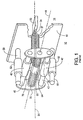
- the solution to venting the HFFB's used involves fabricating a stage having a chuck, or payload, in high vacuum and a bearing portion in atmosphere. Separation of vacuum and atmosphere is accomplished through the use of flexible metal bellows. A simplified sectional view of this solution is shown in FIG. 1.
- linear motion of chuck or payload 20 is provided in a first axis 54 by rods 50 and collars 52, and in a second axis 44, orthogonal to the first axis, by rods 40 and collars 42.
- Rods 40, 50 and collars 42, 52 are shown on a first side 12 of a vacuum chamber element 10 which is at atmospheric pressure.
- Payload 20 is shown on a low pressure, second side 14 of element 10.
- payload 20 is coupled to shaft 60 via cantilever arm 24 contained within flexible bellows 37.
- Shaft 60 is contained within flexible bellows 30, 35 and housing 65.
- Plate 70 couples bellows 37 to housing 65 with cantilever arm 24 passing through an orifice (not shown) within plate 70.
- Flexible bellows 37 have an essentially circular cross-section with a diameter sufficiently large to accommodate the full extent of linear motion required along axis 44 and is vacuum coupled at one end to chamber element 10 and at the other end to plate 70.
- Essentially circular orifices (not shown) with a diameter approximately equal that of bellows 37 are provided in chamber element 10 and plate 70 where coupled to bellows 37. In this manner, linear motion along axis 44 is not restricted while maintaining vacuum within bellows 37 (the vacuum coupling of the ends of flexible bellows 37 is not shown due to the perspective view of FIG. 1). Linear motion along axis 54 is accommodated through the compression or extension of bellows 37.
- bellows 37 For a mask patterning system requiring 18 centimeters (cm) of travel in each axis, bellows 37 requires an internal diameter of 18 cm plus the size of arm 24 and design clearances that are deemed necessary and appropriate. Additionally, bellows 37 would have to be capable of expansion and compression of in excess of that same 18 cm. As payload 20 and arm 24 are cantilevered from shaft 60 and through plate 70, they must be as light as possible while still having substantial structural strength, thus materials such as beryllium are employed.
- the MEBES-4500 While the design of the MEBES-4500 is proven, and provides high performance, its cost is high. First, it requires the use of bellows fabricated from extremely strong materials, such as stainless steel, to withstand the force of the pressure differential between the low pressure of the exposure chamber and atmosphere. Second, it requires that the payload be cantilevered thus requiring the use of ultra light weight materials in the payload assembly to reduce the mass at the end of the lever. A third problem that results is the mass of the bearing assembly and the stiffness of the bellows material, resulting in a design with a form factor that is approximately six times the stage travel in each direction. In addition, the mass of the design and stiffness of the bellows require considerable force to produce the desired motion requiring the use of oversized force generating devices.
- the present invention is directed to a linear motion device as claimed in claim 1 that provides for the use of fluid bearings within a vacuum chamber at a first pressure significantly less than one atmosphere.
- the linear motion device can be used in combination with other such linear motion devices to provide linear motion in two or more directions.
- the present invention provides an alternate linear motion device that is truly vacuum compatible by incorporating the fluid bearing in a vacuum enclosure.
- the vacuum enclosure maintains a second pressure significantly less than one atmosphere but greater than the first pressure, thus allowing the use of light weight, flexible bellows materials such as polyfluorinated hydrocarbons, polyimides and plastics such as polyethylene polymers.
- linear motion device entirely within a vacuum chamber allows for direct, rigid attachment of a moveable payload or chuck to a portion of the fluid bearing.
- cantilever attachment of payload employed in the prior art is not required.
- the present linear motion device by and through its ability to be completely contained within a vacuum, reduces manufacturing costs while providing enhanced performance for electron beam exposure and mask patterning and other applications.
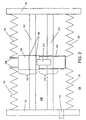
- FIG. 2 a simplified cross-sectional view along a long axis of a linear motion device 100 according to an embodiment of the present invention is shown.
- Device 100 is fully contained within a vacuum chamber (not shown) and includes three main assemblies, a vacuum enclosure 130, a fluid bearing 150 and a force generating device (FGD) 210.
- FGD force generating device
- Vacuum enclosure 130 includes a pair of flexible bellows 132, a rigid coupling 134 and a pair of rigid mounting plates 120. Each of the pair of flexible bellows 132 is coupled at one end to one of the pair of rigid mounting plates 120 and at another end to rigid coupling 134.
- a vacuum port 110 provides a means of evacuating enclosure 130 to a pressure below that of atmospheric pressure.
- Rigid mounting plates 120 are plates specifically designed to provide vacuum closure for ends of bellows 132, and as discussed below, mounting of bearing rod 152. Alternately, mounting plates 120 are interior surfaces of the vacuum chamber within which vacuum enclosure 130 is contained.
- Bearing 150 includes a bearing rod 152 fixed at each end to one of the pair of rigid mounting plates 120.
- a bearing collar 154 is disposed about rod 152 forming a uniform gap 156.
- a fluid film (not shown) is supplied under pressure to fill and maintain gap 156 allowing for virtually frictionless movement of bearing collar 154 along the long axis of bearing rod 152.
- Fluid bearing 150 when supplied with a fluid film under pressure, is often referred to as a hydrostatic fluid film bearing (HFFB).
- HFFB hydrostatic fluid film bearing
- HFFB's are commonly employed, however, other fluid bearings, for example hydrostatic fluid film bearings having a liquid film, where the liquid has a very low vapor pressure for example 1,33 ⁇ 10 -2 Pa or less, can also be used.
- FGD 210 includes a force device stator 212 and a force device slider 214.
- Force device slider 214 is fixed to bearing collar 154 and is positioned to allow electrical coupling with force device stator 212.
- an electric current provided to force device slider 214 will cause it to electrically couple to force device stator 212 and a force thus generated is applied to bearing collar 154 resulting in linear motion along the long axis of rod 152.
- FGD 210 in FIG. 2 is commonly referred to as a linear motor.
- a linear motor is not the only type of device that is employed to impart force to collar 154.
- a ball screw can be substituted for force device stator 212 and a ball nut can be used in place of force device slider 214.
- Still other methods, for example hydraulic cylinders, of imparting force to generate relative motion between bearing collar 154 and bearing rod 152 may also be used.
- Linear motion device 100 is used, e.g. to provide linear motion in applications such as an electron beam exposure system capable of patterning masks for the semiconductor industry and other applications were linear travel in excess of approximately 7.6 cm is required.
- device 100 is fully contained within a main vacuum chamber of the system.
- a first pressure in the range of approximately 1,33 ⁇ 10 -3 to 1,33 ⁇ 10 -5 Pa is required for the vacuum chamber, however higher pressures, for example as high as approximately 1,33 ⁇ 10 -2 Pa, or lower pressures, for example as low as approximately 1,33 ⁇ 10 -6 Pa can be used.
- device 100 includes, as it has been discussed, vacuum enclosure 130.
- Vacuum enclosure 130 is maintained at.a second pressure, different from the first pressure.
- enclosure 130 is maintained at a pressure in the range of approximately 1,33 ⁇ 10 3 Pa to just above the first pressure. In this manner, the pressure differential between the vacuum chamber and the interior of enclosure 130, and the resulting force is made quite small.
- the bellows must withstand a pressure differential between the vacuum chamber, at a first pressure of, for example approximately 1,33 ⁇ 10 -4 Pa, and one atmosphere. This corresponds to a force in excess of 1 Kg/cm 2 and is reason for the requirement found in the MEBES-4500 for bellows fabricated from materials such as stainless steel.
- device 100 provides vacuum enclosure 130 which can be maintained at a second pressure significantly lower than one atmosphere. Thus with enclosure 130 maintained at a pressure of, for example 13,3 Pa, the force applied by the pressure differential is reduced to about 0.14 gm/cm 2 .
- FIG. 3 another embodiment, linear motion device 102, of the present invention is shown.
- Bellows 132 of FIG. 2 is shown in FIG. 3 as compressed bellows 136 and extended bellows 138.
- collar 154 of FIG. 2 is shown as a pair of collars 155 and coupling 134 of FIG. 2 is shown as coupling 135 where coupling 135 serves to couple each of collar pair 155 to one another as well as couple compressed bellows 136 to extended bellows 138.
- force device slider 214 of FIG. 2 is shown as pair of force device sliders 215,
- Fig. 4 is a simplified top down view of a dual axis linear motion device 104 according to another embodiment of the present invention.
- a dual axis linear motion device 104 for ease of illustration and explanation, only motion collars, motion rods, rigid mounting plates 120 and payload 300 are shown.
- the embodiment of FIG. 4 is commonly referred to as a X-Y Stage 104 and also encompasses a vacuum enclosure for each rod 152 and collar pair 155 in the manner of the embodiment of FIG. 3, and a vacuum enclosure for each rod 142 and collar 144 in the manner of FIG. 2.
- Device or stage 104 includes a pair of motion rods 152 oriented in a first direction, and a pair of motion rods 142, oriented in a second direction, orthogonal to the first direction.
- Each motion rod 152 is fixably coupled to rigid mounting plates 120 at each end. Thus a rigid, structurally sound mounting basis for device 104 is established through the mounting of rods 152.
- each motion rod 152 has a motion collar 156' and a motion collar 158 disposed thereon in a manner previously described.
- Each motion rod 142 is fixably coupled between either pair of collars 156' or pair of collars 158.
- pairs of collars 156', 158 move in a first direction with respect to a rods 152, motion rods 142 also move in that first direction.
- Each motion rod 142 has a motion collar 144 disposed thereon in a manner previously described and is fixably coupled to payload 300.
- payload 300 can effect linear motion in two orthogonal directions through the relative linear motion of collars 156' and 158 with respect to rods 152 combined with the relative linear motion of collars 144 with respect to rods 142.
- payload 300 through its fixable coupling to motion collar 144, is rigidly fixed to mounting plates 120 (FIG. 4).
- payload 300 is not cantilevered and vibration caused by such a cantilevered structure is eliminated.
- elimination of the cantilever design greatly reduces this requirement and allows fabrication of payload 300 from more economical materials.
- linear motion device or stage 104 Another benefit of linear motion device or stage 104 is a reduction in form factor or size. As previously discussed, the MEBES-4500 requires a form factor of six times linear travel in each direction. On the other hand, linear motion device 104 through the use of light weight, highly flexible bellows reduces that form factor to four times linear travel, or less, in each direction. Thus the form factor of stage 104 approaches that of the three times linear travel in each direction found in optical microlithography systems that operate at atmospheric pressure. Additionally, the light weight and flexibility of the bellows materials reduces the amount of force required to produce the desired motion. Both of these benefits greatly enhance overall performance with regard to travel requirements and provide for meeting industry needs well into the future.
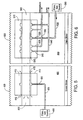
- FIGs. 5 and 6 two alternate embodiments of collars according to the present invention are shown.
- bearing collar 410 is disposed about bearing rod 400 forming uniform gap 415.
- a portion of flexible bellows 450 coupled at one end to a rigid coupling (not shown) and at another end to a rigid mounting plate (not shown) forming vacuum enclosure 460.
- Fluid inlet 420 is positioned at approximately a midpoint of collar 410 and is coupled to flexible tube 425 at one end.
- Flexible tube 425 is also coupled to pressurized gas source 490 at another end. It will be understood that gas source 490 is positioned in a remote location, preferably at atmospheric pressure.
- Tube 425 supplies a pressurized gas, for example air, to fill gap 415 and maintain a separation of collar 410 and rod 400.
- gas supplied through tube 425 escapes gap 415 at ends 412 of collar 410 into enclosure 460.
- a vacuum pump (not shown) used to evacuate enclosure 460, is also used to vent this gas to atmosphere to provide for movement of collar 410 over rod 400.
- bearing collar 510 is disposed about bearing rod 500 to form uniform gap 515.
- a portion of flexible bellows 550 coupled at one end to a rigid coupling (not shown) and at another end to a rigid mounting plate (not shown) are shown to form vacuum enclosure 560.
- Fluid inlet 520 is positioned at approximately a midpoint of collar 510 and is coupled to flexible tube 525 at one end.
- Flexible tube 525 is also coupled to pressurized gas source 590 at another end.
- a pair of first venting ports 530 are positioned on either side of inlet 520 and a pair of second venting ports 540 are positioned between each first port 530 and end 512 of collar 510.
- Second ports 540 are coupled to differential vacuum source 580 through flexible vacuum tubing 535.
- First ports 530 are coupled to atmosphere through flexible tubing 545.
- Flexible tubing 525 and 545 taken in combination with flexible vacuum tubing 535 is commonly referred as a service loop.
- a differentially vented bearing collar is provided where a gas supplied through inlet 520 is vented before it can reach enclosure 560.
- HFFB's are fabricated in a variety of configurations; these are compatible with embodiments of the present invention. These alternate configurations when combined with the disclosure presented herein are deemed to be within the spirit and scope of the present invention.
- an HFFB configured to use a low vapor pressure liquid as a bearing support fluid, or configurations that employ differing venting configurations are deemed to be within the scope and spirit of the present invention.
- Payload or chuck 700 is shown contained within vacuum chamber 800 fixably coupled to first pair of linear motion devices (not shown), oriented in a first direction and wholly contained within first pair of vacuum enclosures 715.
- First motion devices are fixably coupled to second pair of linear motion devices, oriented in a second direction orthogonal to the first direction.
- Second motion devices are wholly contained within pair of second vacuum enclosures 720.
- linear motion in two orthogonal axes is provided for chuck 700 within vacuum chamber 800.
- second pair of linear motion devices (not shown) are fixably mounted through rigid mounting plates 730 at ends of second vacuum enclosures 720 to vacuum chamber 800 providing for a rigid, stable mounting of first pair of linear motion devices and payload 700.
- mounting of payload or chuck 700 does not require a cantilever design and enhanced stability is achieved to provide enhanced performance.
- Vacuum chamber 800 is evacuated to the first pressure through vacuum coupling 760 to vacuum pump 765.
- First and second vacuum enclosures 715, 720 are evacuated to the second pressure through vacuum couplings 750 to vacuum pump 755.
- This reduced differential then allows the use of lighter, more flexible bellows materials and when combined with the rigid fixed mounting within vacuum chamber 800, also results in a smaller form factor for the overall design.
- the new linear motion device provides for a rigid mounting of a payload, for example to form an X-Y motion stage, while entirely contained within a vacuum chamber thus eliminating the need for designs incorporating cantilevers.
- the new device additionally provides for use of hydrostatic fluid film bearings within vacuum enclosures that are maintained at a pressure between atmosphere and the pressure of the vacuum chamber.
- This feature allows for the use of lightweight, flexible bellows materials thus reducing the mass of designs as compared to the prior art where relatively inflexible materials, such as stainless steel, are required.
- This reduction in mass, due in part to the bellows makes possible stage designs that have a reduced form factor or size than currently required.
- form factors approaching those of atmospheric designs are possible.
- all of the aforementioned improvements combine to result in greatly reduced cost to manufacture while also providing for enhanced performance.
Landscapes
- Engineering & Computer Science (AREA)
- General Engineering & Computer Science (AREA)
- Mechanical Engineering (AREA)
- General Physics & Mathematics (AREA)
- Physics & Mathematics (AREA)
- Public Health (AREA)
- Epidemiology (AREA)
- Environmental & Geological Engineering (AREA)
- Health & Medical Sciences (AREA)
- Chemical & Material Sciences (AREA)
- Analytical Chemistry (AREA)
- Exposure Of Semiconductors, Excluding Electron Or Ion Beam Exposure (AREA)
- Electron Beam Exposure (AREA)
- Magnetic Bearings And Hydrostatic Bearings (AREA)
Abstract
Description
- This invention relates to electron beam exposure systems and more specifically to a vacuum compatible linear motion device for an electron beam exposure system.
- Electron beam exposure systems, used for example to pattern masks for the semiconductor industry, require a very high precision linear motion device or stage to position a working piece relative to the electron beam. Typical requirements for this device or stage are straightness of travel in pitch, roll and yaw of 2 arc seconds or better, and vibration levels that are less than one thousandth of a gravity (m-g). Two approaches to meeting these requirements are known and used. A first uses hydrostatic fluid film bearings, a second rolling element bearings.
- A linear fluid bearing typically consists of a rod and a collar that can traverse a long axis of the rod. Almost frictionless motion can be obtained by providing a bearing support fluid between the rod and collar. Typically, pressurized air is used as this bearing support fluid. Air is of course readily available, easy to clean, both prior and after use, and can be vented safely to the environment, without the need to collect or recycle.
- On the other hand, a rolling element bearing (REB) has a rolling element, typically balls or rollers, that essentially replaces the fluid of the fluid bearing. This rolling element requires lubrication, and while only a small amount of lubricant is needed, the lubricant is a potential source of contamination.
- In atmospheric applications, for example optical microlithography, fluid bearings or hydrostatic fluid film bearings (HFFB's) are typically selected over REB's despite a higher cost due primarily to providing a pressurized fluid and the venting thereof. This choice is primarily due to HFFB's better performance with regard to the travel and vibration requirements discussed above
- In a vacuum however, especially the high vacuum required by electron beam exposure systems (1,33 × 10⁻³ - 1,33 × 10⁻⁵ Pa), the use of air, or any fluid, as the bearing support fluid becomes significantly more difficult than at atmospheric pressure due to the need to vent the fluid without affecting the vacuum integrity. As a result, most manufacturers of electron beam exposure systems use roller element bearings. Thus accepting lower performance and a significant risk of contamination.
- One manufacturer, Etec Systems, Inc., of Hayward, California uses HFFB's in its MEBES-4500 electron beam patterning system. The solution to venting the HFFB's used involves fabricating a stage having a chuck, or payload, in high vacuum and a bearing portion in atmosphere. Separation of vacuum and atmosphere is accomplished through the use of flexible metal bellows. A simplified sectional view of this solution is shown in FIG. 1.
- As seen in FIG. 1, linear motion of chuck or
payload 20 is provided in afirst axis 54 byrods 50 andcollars 52, and in asecond axis 44, orthogonal to the first axis, byrods 40 andcollars 42.Rods collars first side 12 of avacuum chamber element 10 which is at atmospheric pressure.Payload 20 is shown on a low pressure,second side 14 ofelement 10. To isolateside 12 fromside 14,payload 20 is coupled toshaft 60 viacantilever arm 24 contained withinflexible bellows 37.Shaft 60 is contained withinflexible bellows couples bellows 37 to housing 65 withcantilever arm 24 passing through an orifice (not shown) withinplate 70. -
Flexible bellows 37 have an essentially circular cross-section with a diameter sufficiently large to accommodate the full extent of linear motion required alongaxis 44 and is vacuum coupled at one end tochamber element 10 and at the other end toplate 70. Essentially circular orifices (not shown) with a diameter approximately equal that ofbellows 37 are provided inchamber element 10 andplate 70 where coupled tobellows 37. In this manner, linear motion alongaxis 44 is not restricted while maintaining vacuum within bellows 37 (the vacuum coupling of the ends offlexible bellows 37 is not shown due to the perspective view of FIG. 1). Linear motion alongaxis 54 is accommodated through the compression or extension ofbellows 37. - Thus for a mask patterning system requiring 18 centimeters (cm) of travel in each axis,
bellows 37 requires an internal diameter of 18 cm plus the size ofarm 24 and design clearances that are deemed necessary and appropriate. Additionally,bellows 37 would have to be capable of expansion and compression of in excess of that same 18 cm. Aspayload 20 andarm 24 are cantilevered fromshaft 60 and throughplate 70, they must be as light as possible while still having substantial structural strength, thus materials such as beryllium are employed. - while the design of the MEBES-4500 is proven, and provides high performance, its cost is high. First, it requires the use of bellows fabricated from extremely strong materials, such as stainless steel, to withstand the force of the pressure differential between the low pressure of the exposure chamber and atmosphere. Second, it requires that the payload be cantilevered thus requiring the use of ultra light weight materials in the payload assembly to reduce the mass at the end of the lever. A third problem that results is the mass of the bearing assembly and the stiffness of the bellows material, resulting in a design with a form factor that is approximately six times the stage travel in each direction. In addition, the mass of the design and stiffness of the bellows require considerable force to produce the desired motion requiring the use of oversized force generating devices.
- An alternate solution to the massive, stiff bellows required to sustain a one atmosphere pressure differential would be desirable. Thus there exists the need for an alternate solution to providing linear motion to a vacuum system such as the MEBES-4500.
- One such solution is proposed in U.S. Patent No. 4,462,580 entitled "HYDRAULICALLY DRIVEN X-Y STAGE", issued July 31, 1984 to Robert J. Nielsen. Nielsen proposed the use of oil driven hydraulic cylinders to drive the stage. Nielsen discloses that the oil containing portion of the cylinder can be contained within an enclosure comprised in part of bellows, and that this enclosure can be maintained at a pressure less than atmosphere. However, Nielsen provides that the stage is of a cantilever design at the end of rod portion of the hydraulic cylinder. In addition, while Nielsen provides that the oil containing portion is within an enclosure, the rod, as it extends into the working chamber passes through an O-ring seal. As it is known, such seals require lubrication and can create contamination due to friction with the rod. Failure of the O-ring would cause the oil containing enclosure to be exposed to the working chamber resulting in contamination.
- The present invention is directed to a linear motion device as claimed in
claim 1 that provides for the use of fluid bearings within a vacuum chamber at a first pressure significantly less than one atmosphere. The linear motion device can be used in combination with other such linear motion devices to provide linear motion in two or more directions. - Thus the present invention provides an alternate linear motion device that is truly vacuum compatible by incorporating the fluid bearing in a vacuum enclosure. The vacuum enclosure maintains a second pressure significantly less than one atmosphere but greater than the first pressure, thus allowing the use of light weight, flexible bellows materials such as polyfluorinated hydrocarbons, polyimides and plastics such as polyethylene polymers.
- Additionally, having the linear motion device entirely within a vacuum chamber allows for direct, rigid attachment of a moveable payload or chuck to a portion of the fluid bearing. Thus the cantilever attachment of payload employed in the prior art is not required.
- The combination of light weight, flexible bellows and the elimination of the requirement of a cantilever design are factors that allow for the design of vacuum compatible dual axis devices that approach the size or form factor of dual axis devices designed for atmospheric operation only.
- Finally the present linear motion device, by and through its ability to be completely contained within a vacuum, reduces manufacturing costs while providing enhanced performance for electron beam exposure and mask patterning and other applications.
-
- FIG. 1 is a simplified perspective view, partly cut away, of a portion of the stage assembly of the MEBES-4500;
- FIG. 2 is a simplified cross-sectional view through a long axis of a linear motion device according to an embodiment of the present invention;
- FIG. 3 is a simplified cross-sectional view through a long axis of a linear motion device according to another embodiment of the present invention;
- FIG. 4 is a simplified top down view of a dual axis linear motion device according to another embodiment of the present invention;
- FIG. 5 is a simplified cross sectional view of a collar and a portion of a rod according to an embodiment of the present invention;
- FIG. 6 is a simplified cross sectional view of a collar and a portion of a rod according to another embodiment of the present invention; and
- FIG. 7 is a simplified perspective view with cut out portions of an embodiment of the present invention.
-
- Embodiments of the present invention will be described with reference to the aforementioned figures. It will be understood that these drawings are simplified for ease of understanding and description only.
- Referring now to FIG. 2, a simplified cross-sectional view along a long axis of a
linear motion device 100 according to an embodiment of the present invention is shown.Device 100 is fully contained within a vacuum chamber (not shown) and includes three main assemblies, avacuum enclosure 130, afluid bearing 150 and a force generating device (FGD) 210. -
Vacuum enclosure 130 includes a pair offlexible bellows 132, arigid coupling 134 and a pair of rigid mountingplates 120. Each of the pair offlexible bellows 132 is coupled at one end to one of the pair of rigid mountingplates 120 and at another end torigid coupling 134. Avacuum port 110 provides a means of evacuatingenclosure 130 to a pressure below that of atmospheric pressure. Rigid mountingplates 120 are plates specifically designed to provide vacuum closure for ends ofbellows 132, and as discussed below, mounting of bearingrod 152. Alternately, mountingplates 120 are interior surfaces of the vacuum chamber within whichvacuum enclosure 130 is contained. - Bearing 150 includes a bearing
rod 152 fixed at each end to one of the pair of rigid mountingplates 120. Abearing collar 154 is disposed aboutrod 152 forming auniform gap 156. Typically, a fluid film (not shown) is supplied under pressure to fill and maintaingap 156 allowing for virtually frictionless movement of bearingcollar 154 along the long axis of bearingrod 152.Fluid bearing 150, when supplied with a fluid film under pressure, is often referred to as a hydrostatic fluid film bearing (HFFB). It will be understood by one with skill in the art, that HFFB's are commonly employed, however, other fluid bearings, for example hydrostatic fluid film bearings having a liquid film, where the liquid has a very low vapor pressure for example 1,33 × 10⁻² Pa or less, can also be used. -
FGD 210 includes aforce device stator 212 and aforce device slider 214.Force device slider 214 is fixed to bearingcollar 154 and is positioned to allow electrical coupling withforce device stator 212. Thus an electric current provided to forcedevice slider 214 will cause it to electrically couple to forcedevice stator 212 and a force thus generated is applied to bearingcollar 154 resulting in linear motion along the long axis ofrod 152.FGD 210 in FIG. 2 is commonly referred to as a linear motor. However, a linear motor is not the only type of device that is employed to impart force tocollar 154. For example, a ball screw can be substituted forforce device stator 212 and a ball nut can be used in place offorce device slider 214. Still other methods, for example hydraulic cylinders, of imparting force to generate relative motion between bearingcollar 154 and bearingrod 152 may also be used. -
Linear motion device 100, as described, is used, e.g. to provide linear motion in applications such as an electron beam exposure system capable of patterning masks for the semiconductor industry and other applications were linear travel in excess of approximately 7.6 cm is required. In such an application,device 100 is fully contained within a main vacuum chamber of the system. In such systems, a first pressure in the range of approximately 1,33 × 10⁻³ to 1,33 × 10⁻⁵ Pa is required for the vacuum chamber, however higher pressures, for example as high as approximately 1,33 × 10⁻² Pa, or lower pressures, for example as low as approximately 1,33 × 10⁻⁶ Pa can be used. To its advantage,device 100 includes, as it has been discussed,vacuum enclosure 130.Vacuum enclosure 130 is maintained at.a second pressure, different from the first pressure. For example,enclosure 130 is maintained at a pressure in the range of approximately 1,33 × 10³ Pa to just above the first pressure. In this manner, the pressure differential between the vacuum chamber and the interior ofenclosure 130, and the resulting force is made quite small. - The magnitude of this reduction is best visualized by example. In a prior art system such as the MEBES-4500, the bellows must withstand a pressure differential between the vacuum chamber, at a first pressure of, for example approximately 1,33 × 10⁻⁴ Pa, and one atmosphere. This corresponds to a force in excess of 1 Kg/cm2 and is reason for the requirement found in the MEBES-4500 for bellows fabricated from materials such as stainless steel. On the other hand,
device 100 providesvacuum enclosure 130 which can be maintained at a second pressure significantly lower than one atmosphere. Thus withenclosure 130 maintained at a pressure of, for example 13,3 Pa, the force applied by the pressure differential is reduced to about 0.14 gm/cm2. - This reduction in force on the bellows allows the selection of materials for
bellows 132 that are light in weight and highly flexible, without significant regard for the strength needed to resist the aforementioned large pressure differential of the prior art. Thus highly flexible materials such as polyfluorinated hydrocarbons (Teflon® FEP, Teflon® PFA or Teflon® PTFE (Teflon is a registered trademark of DuPont, Inc.)), polyimides (Kapton® H, Kapton® K, Kapton® HK, Kapton® FN (Kapton is a registered trademark of DuPont, Inc.)) and various plastic materials such as polyethylene polymers are suitable. - In FIG. 3, another embodiment,
linear motion device 102, of the present invention is shown.Bellows 132 of FIG. 2 is shown in FIG. 3 ascompressed bellows 136 and extended bellows 138. Additionally,collar 154 of FIG. 2 is shown as a pair ofcollars 155 andcoupling 134 of FIG. 2 is shown ascoupling 135 wherecoupling 135 serves to couple each ofcollar pair 155 to one another as well as couple compressedbellows 136 to extended bellows 138. Finally,force device slider 214 of FIG. 2 is shown as pair offorce device sliders 215, - Fig. 4 is a simplified top down view of a dual axis
linear motion device 104 according to another embodiment of the present invention. For ease of illustration and explanation, only motion collars, motion rods, rigid mountingplates 120 andpayload 300 are shown. It will be understood, that the embodiment of FIG. 4 is commonly referred to as aX-Y Stage 104 and also encompasses a vacuum enclosure for eachrod 152 andcollar pair 155 in the manner of the embodiment of FIG. 3, and a vacuum enclosure for eachrod 142 andcollar 144 in the manner of FIG. 2. - Device or
stage 104 includes a pair ofmotion rods 152 oriented in a first direction, and a pair ofmotion rods 142, oriented in a second direction, orthogonal to the first direction. Eachmotion rod 152 is fixably coupled to rigid mountingplates 120 at each end. Thus a rigid, structurally sound mounting basis fordevice 104 is established through the mounting ofrods 152. Additionally, eachmotion rod 152 has a motion collar 156' and amotion collar 158 disposed thereon in a manner previously described. Eachmotion rod 142 is fixably coupled between either pair of collars 156' or pair ofcollars 158. Thus as pairs ofcollars 156', 158 move in a first direction with respect to arods 152,motion rods 142 also move in that first direction. Eachmotion rod 142 has amotion collar 144 disposed thereon in a manner previously described and is fixably coupled topayload 300. Thus,payload 300 can effect linear motion in two orthogonal directions through the relative linear motion ofcollars 156' and 158 with respect torods 152 combined with the relative linear motion ofcollars 144 with respect torods 142. - It will be understood that
payload 300 through its fixable coupling tomotion collar 144, is rigidly fixed to mounting plates 120 (FIG. 4). Thuspayload 300 is not cantilevered and vibration caused by such a cantilevered structure is eliminated. In addition, while overall system performance can still benefit from lightweight construction ofpayload 300, elimination of the cantilever design greatly reduces this requirement and allows fabrication ofpayload 300 from more economical materials. - Another benefit of linear motion device or
stage 104 is a reduction in form factor or size. As previously discussed, the MEBES-4500 requires a form factor of six times linear travel in each direction. On the other hand,linear motion device 104 through the use of light weight, highly flexible bellows reduces that form factor to four times linear travel, or less, in each direction. Thus the form factor ofstage 104 approaches that of the three times linear travel in each direction found in optical microlithography systems that operate at atmospheric pressure. Additionally, the light weight and flexibility of the bellows materials reduces the amount of force required to produce the desired motion. Both of these benefits greatly enhance overall performance with regard to travel requirements and provide for meeting industry needs well into the future. - Turning now to FIGs. 5 and 6, two alternate embodiments of collars according to the present invention are shown. In FIG. 5, bearing
collar 410 is disposed about bearingrod 400 forminguniform gap 415. A portion offlexible bellows 450 coupled at one end to a rigid coupling (not shown) and at another end to a rigid mounting plate (not shown) formingvacuum enclosure 460.Fluid inlet 420 is positioned at approximately a midpoint ofcollar 410 and is coupled toflexible tube 425 at one end.Flexible tube 425 is also coupled topressurized gas source 490 at another end. It will be understood thatgas source 490 is positioned in a remote location, preferably at atmospheric pressure.Tube 425 supplies a pressurized gas, for example air, to fillgap 415 and maintain a separation ofcollar 410 androd 400. In the embodiment of FIG. 5, gas supplied throughtube 425 escapesgap 415 at ends 412 ofcollar 410 intoenclosure 460. A vacuum pump (not shown) used to evacuateenclosure 460, is also used to vent this gas to atmosphere to provide for movement ofcollar 410 overrod 400. - In FIG. 6, an alternate embodiment for venting is depicted. Thus, bearing
collar 510 is disposed about bearingrod 500 to formuniform gap 515. A portion offlexible bellows 550 coupled at one end to a rigid coupling (not shown) and at another end to a rigid mounting plate (not shown) are shown to formvacuum enclosure 560.Fluid inlet 520 is positioned at approximately a midpoint ofcollar 510 and is coupled toflexible tube 525 at one end.Flexible tube 525 is also coupled topressurized gas source 590 at another end. A pair of first ventingports 530 are positioned on either side ofinlet 520 and a pair of second ventingports 540 are positioned between eachfirst port 530 and end 512 ofcollar 510.Second ports 540 are coupled to differential vacuum source 580 throughflexible vacuum tubing 535.First ports 530 are coupled to atmosphere throughflexible tubing 545.Flexible tubing flexible vacuum tubing 535 is commonly referred as a service loop. Thus, as one skilled in the art knows, a differentially vented bearing collar is provided where a gas supplied throughinlet 520 is vented before it can reachenclosure 560. - As it is known, HFFB's are fabricated in a variety of configurations; these are compatible with embodiments of the present invention. These alternate configurations when combined with the disclosure presented herein are deemed to be within the spirit and scope of the present invention. For example, an HFFB configured to use a low vapor pressure liquid as a bearing support fluid, or configurations that employ differing venting configurations are deemed to be within the scope and spirit of the present invention.
- Referring now to FIG. 7, a simplified perspective view, with cut-out portions, of an embodiment of the present invention within an electron beam mask patterning system is shown. Payload or chuck 700 is shown contained within
vacuum chamber 800 fixably coupled to first pair of linear motion devices (not shown), oriented in a first direction and wholly contained within first pair ofvacuum enclosures 715. - First motion devices are fixably coupled to second pair of linear motion devices, oriented in a second direction orthogonal to the first direction. Second motion devices are wholly contained within pair of
second vacuum enclosures 720. Thus linear motion in two orthogonal axes is provided forchuck 700 withinvacuum chamber 800. - As described with respect to FIG. 4, second pair of linear motion devices (not shown) are fixably mounted through rigid mounting
plates 730 at ends ofsecond vacuum enclosures 720 tovacuum chamber 800 providing for a rigid, stable mounting of first pair of linear motion devices andpayload 700. Thus mounting of payload or chuck 700 does not require a cantilever design and enhanced stability is achieved to provide enhanced performance. -
Vacuum chamber 800 is evacuated to the first pressure throughvacuum coupling 760 tovacuum pump 765. First andsecond vacuum enclosures vacuum couplings 750 tovacuum pump 755. Thus a reduced pressure differential, as previously discussed, is obtained. This reduced differential then allows the use of lighter, more flexible bellows materials and when combined with the rigid fixed mounting withinvacuum chamber 800, also results in a smaller form factor for the overall design. - Thus a new, vacuum compatible linear motion device has been disclosed. The new linear motion device provides for a rigid mounting of a payload, for example to form an X-Y motion stage, while entirely contained within a vacuum chamber thus eliminating the need for designs incorporating cantilevers. The new device additionally provides for use of hydrostatic fluid film bearings within vacuum enclosures that are maintained at a pressure between atmosphere and the pressure of the vacuum chamber. This feature allows for the use of lightweight, flexible bellows materials thus reducing the mass of designs as compared to the prior art where relatively inflexible materials, such as stainless steel, are required. This reduction in mass, due in part to the bellows, makes possible stage designs that have a reduced form factor or size than currently required. Thus form factors approaching those of atmospheric designs are possible. Finally, all of the aforementioned improvements combine to result in greatly reduced cost to manufacture while also providing for enhanced performance.
Claims (42)
- A vacuum compatible linear motion device (100; 102; 104) comprising:a vacuum chamber (800) for sustaining a first pressure substantially less than one atmosphere;a first enclosure (130; 715) within the vacuum chamber (800) for maintaining a second pressure substantially less than one atmosphere and greater than the first pressure,said first enclosure (130; 715) enclosing a first fluid bearing (144; 150) fixably coupled to an inside surface of said vacuum chamber (800), wherein said first fluid bearing (144; 150) has an axis oriented in a first direction; anda payload (300) within said vacuum chamber (800), wherein said payload (300) is fixably coupled to said first fluid bearing (144, 150) whereby linear motion is provided for said payload (300).
- The device of Claim 1 wherein said payload (300) has a range of linear motion in said first direction of at least approximately 7.6 cm.
- The device of Claim 2 wherein said payload (300) is free to move linearly in said first direction with straightness of travel in pitch, roll and yaw of less than approximately 2 arc-seconds and vibration of less than 1/1000 gravity.
- The device of Claim 1 wherein said first fluid bearing (144, 150) is a hydrostatic fluid film bearing comprising:a first rod (152) fixably coupled to said vacuum chamber;a first collar (154) disposed about a portion of said first rod (152) and fixably coupled to said payload wherein said first collar (154) provides linear motion along the first direction with respect to said first rod (152); anda bearing support fluid disposed between said first collar (154) and said first rod (152).
- The device of Claim 4 wherein said first rod (152) further comprises first and second ends wherein said first and second ends are fixably coupled to said vacuum chamber.
- The device of Claim 1 wherein said first enclosure is comprised of a bellows (132) fabricated from a flexible polyfluorinated hydrocarbon material or a flexible polyimide material.
- The device of Claim 1 wherein said first enclosure (130) is comprised of a bellows (132) fabricated from a flexible polyethylene material.
- The device of Claim 4 further comprising a force generating device (210) coupled to said first fluid bearing (150) wherein said force generating device (210) provides force for moving said first collar (154) with respect to said first rod (152).
- The device of Claim 8 wherein said force generating device (210) is enclosed within said first enclosure (130).
- The device of Claim 9 wherein said force generating device (210) is a linear motor.
- The device of Claim 4 wherein said bearing support fluid is comprised of air.
- The device of Claim 4 wherein said bearing support fluid is a liquid having a vapor pressure below approximately 1,33 x 10⁻² Pa.
- The device of Claim 4 wherein said bearing support fluid is supplied to said first collar (154) through flexible tubing coupled to said first collar.
- The device of Claim 13 wherein said bearing support fluid is vented within said first enclosure (130).
- The device of Claim 4 said first collar further comprising:a fluid supply portion (520) disposed at a midpoint of said first collar (510);a first pair of venting portions (530) disposed symmetrically about said fluid supply portion;a second pair of venting portions (540) disposed symmetrically about said first pair of venting portions (530); anda service loop comprising flexible tube (545) connections to said fluid supply portion (520) and said first and second pair of venting portions (530, 540), wherein said second venting portion (540) is coupled to a vacuum source having a pressure greater than said second pressure and less than atmospheric pressure and said first venting portion (530) is coupled to atmospheric pressure, and wherein said bearing support fluid is vented through said first and second venting portions (530, 540).
- The device of Claim 1 further comprising:a first vacuum pumping device (765) for maintaining said vacuum chamber (800) at the first pressure; anda second vacuum pumping device for maintaining said first enclosure (715) at the second pressure.
- The device of Claim 1 further comprising:wherein said second fluid bearing (158) is fixably coupled to said first fluid bearing (144) and wherein said payload's (300) fixable coupling to said second fluid bearing (158) is through said first fluid bearing (144), whereby linear motion is provided for said payload (300) in said second direction; anda second fluid bearing (158) oriented in a second direction orthogonal to said first direction,
a second enclosure wherein said vacuum enclosure encloses said second fluid bearing and maintains a second pressure substantially less than atmospheric pressure and higher than the first pressure. - The device of Claim 17 wherein said payload (300) has a range of linear motion in said first and second directions of at least approximately 7.6 cm with straightness of travel in pitch, roll and yaw of less than approximately 2 arc second and vibration of less than 1/1000 gravity.
- The device of Claim 17 wherein said first enclosure (715) and said second enclosure (720) are comprised of a bellows fabricated from a flexible polyfluorinated hydrocarbon material or a polyimide material.
- The device of Claim 17 wherein said first enclosure (715) and said second enclosure (720) are comprised of a bellows fabricated from a polyethylene material.
- The device of Claim 17 further comprising:wherein said first force generating device is enclosed within said first enclosure (715) and said second force generating device is enclosed within said second enclosure (720).a first force generating device for providing force for moving said first collar; anda second force generating device for providing force for moving said second collar;
- The device of Claim 21 wherein said first and second force generating devices are linear motors.
- The device of Claim 17 wherein said first fluid bearing is a hydrostatic fluid film bearing comprising:whereby the fixable coupling of said payload to said first fluid bearing is through said second fluid bearing.a first rod (142) coupled to said vacuum chamber;a first collar (144) disposed about a portion of said first rod wherein said first collar provides linear motion along the first direction with respect to said first rod; andsaid second fluid bearing is a hydrostatic fluid film bearing comprising:a second rod (152) coupled to said first collar;a second collar (158) disposed about a portion of said second rod wherein said second collar provides linear motion along the second direction with respect to said second rod, and wherein said second collar is fixably coupled to said payload (300); anda bearing support fluid disposed between said first collar and said first rod and between said second collar and said second rod, respectively;
- The device of Claim 23 wherein said first fluid bearing, said second fluid bearing and said payload comprise a stage having a form factor of no more than approximately 3 times linear travel in the first and second directions.
- The device of Claim 23 wherein said bearing support fluid is comprised of a gas or a liquid having a vapor pressure below approximately 0.013 Pa (1 x 10⁻⁴ torr).
- The device of Claim 23 wherein said bearing support fluid is supplied to said first and second collars through flexible tubing coupled to said first and second collars (144, 158), respectively and wherein said bearing support fluid is vented within said first and second enclosures, respectively.
- The device of Claim 23, each of said first and second collars (144, 158) further comprising:a fluid supply portion (520) disposed at a midpoint of said each collar;a first pair of venting portions (530) disposed symmetrically about said fluid supply portion (520);a second pair of venting portions (540) disposed symmetrically about said first pair of venting portions; anda service loop comprising flexible tube connections to said fluid supply portion and said first and second pair of venting portions, wherein said second venting portion (540) is coupled to a vacuum source having a pressure greater than said second pressure and less than atmospheric pressure and said first venting portion (530) is coupled to atmospheric pressure, and wherein said bearing support fluid is vented through said first and second venting portions (530, 540).
- The device of Claim 1, (800) comprising:a first bearing rod (142) oriented with a long axis in a first direction wherein said first bearing rod (142) is fixably coupled to more than one surface (120) of said vacuum chamber (800);a first bearing collar (144) movably coupled to said first bearing rod (142);a second bearing rod (152) oriented with a long axis in a second direction, wherein the second direction is perpendicular to the first direction;a second bearing collar (156', 158) movably coupled to said second bearing rod (152) and fixably coupled to said first bearing rod (142);a fluid disposed between said first and second bearing collars (144, 156', 158) and said first and second bearing rods (142, 152), respectively;an apparatus (490, 590) for providing said fluid;the first enclosure (710) being disposed about said first bearing rod (142) and fixably coupled to said first bearing collar and said second bearing collar (156', 158);a second enclosure (720) within said vacuum chamber (800) disposed about said second bearing rod (152) and fixably coupled to said second bearing collar (156', 158) and to a ground portion within said vacuum chamber (800);a first force generating device within said first enclosure (715) wherein said first force generating device provides force for linear motion of said first bearing collar (144) with respect to said first bearing rod (142);a second force generating device within said second enclosure (720) wherein said second force generating device provides force for linear motion of said second bearing collar (156', 158) with respect to said second bearing rod (152);a first vacuum pump (760) for maintaining said vacuum chamber (800) at a first pressure less than approximately 1,33 x 10⁻³ Pa; anda second vacuum pump (755) for maintaining said first and second enclosures (715, 725) at a second pressure of less than approximately 1,33 x 10³ Pa,said payload (300) being free to move linearly in said first direction and/or said second direction with straightness of travel in pitch, roll and yaw of less than approximately 2 arc second and vibration of less than 1/1000 gravity.
- The device of Claim 28 wherein said first force generating device is enclosed within said first enclosure (715) and said second force generating device is enclosed within said second enclosure (720).
- The device of Claim 28 wherein said first and second force generating devices are linear motors.
- The device of Claim 28 wherein said fluid is comprised of air.
- The device of Claim 28 wherein said apparatus for providing said fluid comprises vacuum compatible flexible tubing.
- The device of Claim 28 wherein said fluid disposed between said first and second collars and said first and second rods, respectively is vented within said first and second enclosures, respectively.
- The device of Claim 28 having a form factor of no more than approximately 3 times linear travel in the first and second directions.
- A device according to Claim 1, suitable for an electron beam exposure system wherein the vacuum chamber (800) is provided for performing electron beam exposure at a first vacuum less than approximately 1,33 x 10⁻³ Pa;
a first linear motion device (104) is rigidly mounted within said vacuum chamber (800) and oriented having a long axis in a first direction, wherein said first linear motion device further comprises a first hydrostatic fluid film bearing which is contained within a first enclosure (715) for sustaining a second vacuum less than approximately 1,33 x 10³ Pa;
a second linear motion device (104) fixably coupled to said first linear motion device within said vacuum chamber (800) and oriented having a long axis in a second direction orthogonal to the first direction, wherein said second linear motion device further comprises a second hydrostatic fluid film bearing which is contained within a second enclosure (720) for sustaining a second vacuum less than approximately 1,33 x 10³ Pa; and
a payload (700) is fixably coupled to said second linear motion device whereby dual axis linear motion for said payload is provided. - The device of Claim 35 wherein said payload (300, 700) has a range of linear motion in both the first and second direction of at least 7.6 cm and wherein the range of linear motion has a straightness of travel in pitch, roll and yaw of less than approximately 2 arc sec and vibration of less than 1/1000 gravity.
- The device of Claim 35 wherein the first and second fluid bearing are differentially vented.
- The device of Claim 35 wherein the first and second linear motion devices (104) are entirely contained within said vacuum chamber (800).
- The device of Claim 35 wherein said first and second enclosures (715, 720) further comprising a bellows portion.
- The device of Claim 39 wherein said bellows portion comprises flexible polyfluorinated hydrocarbon material or flexible polyimide material.
- The device of Claim 39 wherein said bellows portion comprises flexible polyethylene material.
- The device of Claim 39 wherein said first linear motion device (104), said second linear motion device (104) and said payload (700) comprise a stage having a form factor of no more than approximately 3 times linear travel in the first and second directions.
Applications Claiming Priority (3)
| Application Number | Priority Date | Filing Date | Title |
|---|---|---|---|
| US766271 | 1996-12-13 | ||
| US08/766,271 US5784925A (en) | 1996-12-13 | 1996-12-13 | Vacuum compatible linear motion device |
| PCT/US1997/022133 WO1998026444A1 (en) | 1996-12-13 | 1997-12-10 | Vacuum compatible linear motion device |
Publications (2)
| Publication Number | Publication Date |
|---|---|
| EP0883892A1 EP0883892A1 (en) | 1998-12-16 |
| EP0883892B1 true EP0883892B1 (en) | 2004-03-10 |
Family
ID=25075937
Family Applications (1)
| Application Number | Title | Priority Date | Filing Date |
|---|---|---|---|
| EP97953082A Expired - Lifetime EP0883892B1 (en) | 1996-12-13 | 1997-12-10 | Vacuum compatible linear motion device |
Country Status (7)
| Country | Link |
|---|---|
| US (1) | US5784925A (en) |
| EP (1) | EP0883892B1 (en) |
| JP (1) | JP4257871B2 (en) |
| KR (1) | KR100282797B1 (en) |
| CA (1) | CA2244994A1 (en) |
| DE (1) | DE69728036T2 (en) |
| WO (1) | WO1998026444A1 (en) |
Families Citing this family (25)
| Publication number | Priority date | Publication date | Assignee | Title |
|---|---|---|---|---|
| WO1999066221A1 (en) * | 1998-06-17 | 1999-12-23 | Nikon Corporation | Static pressure gas bearing, stage device using it, and optical device using it |
| DE19857028A1 (en) * | 1998-12-10 | 2000-07-06 | Rexroth Star Gmbh | Linear guide device |
| JP4354039B2 (en) * | 1999-04-02 | 2009-10-28 | 東京エレクトロン株式会社 | Drive device |
| TW552480B (en) | 1999-04-19 | 2003-09-11 | Asml Netherlands Bv | Moveable support in a vacuum chamber and its application in lithographic projection apparatus |
| NL1015738C2 (en) | 1999-07-28 | 2002-10-15 | Kyocera Corp | Sliding device and associated platform mechanism for use in vacuo. |
| US6300630B1 (en) | 1999-12-09 | 2001-10-09 | Etec Systems, Inc. | Annular differential seal for electron beam apparatus using isolation valve and additional differential pumping |
| JP2001210576A (en) * | 2000-01-25 | 2001-08-03 | Nikon Corp | Load canceling mechanism, combined vacuum chamber, exposure apparatus, and method for manufacturing semiconductor device |
| ATE502224T1 (en) * | 2000-02-01 | 2011-04-15 | Toto Ltd | HYDROSTATIC GAS STORAGE, HYDROSTATIC GAS STORAGE APPARATUS FOR USE IN VACUUM ENVIRONMENTS, AND GAS RECOVERY DEVICE FOR THE HYDROSTATIC GAS STORAGE APPARATUS |
| US6443618B1 (en) * | 2000-07-24 | 2002-09-03 | Moore Epitaxial, Inc. | Particulate free air bearing and seal |
| US6491435B1 (en) | 2000-07-24 | 2002-12-10 | Moore Epitaxial, Inc. | Linear robot |
| US6467960B1 (en) * | 2000-08-18 | 2002-10-22 | Nikon Corporation | Air bearing linear guide for use in a vacuum |
| US6666611B2 (en) * | 2000-08-18 | 2003-12-23 | Nikon Corporation | Three degree of freedom joint |
| JP4534390B2 (en) * | 2001-01-09 | 2010-09-01 | Toto株式会社 | Static pressure gas bearing |
| JP2002252166A (en) * | 2001-02-27 | 2002-09-06 | Canon Inc | Stage apparatus, exposure apparatus, device manufacturing method, and movement guiding method |
| US6614508B2 (en) * | 2001-08-16 | 2003-09-02 | Nikon Corporation | Reversed, double-helical bellows seal |
| US6756706B2 (en) * | 2002-01-18 | 2004-06-29 | Nikon Corporation | Method and apparatus for cooling power supply wires used to drive stages in electron beam lithography machines |
| DE60332681D1 (en) * | 2002-01-22 | 2010-07-08 | Ebara Corp | Stage apparatus |
| JP2004319902A (en) * | 2003-04-18 | 2004-11-11 | Advantest Corp | Stage device and exposure device |
| DE102008019681B4 (en) * | 2008-04-11 | 2013-10-17 | Fraunhofer-Gesellschaft zur Förderung der angewandten Forschung e.V. | By means of aerostatic bearing elements guided table for vacuum application |
| US20100116139A1 (en) * | 2008-11-11 | 2010-05-13 | Chang-Cheng Ho | Chain protector for a linear motion processing machine |
| KR101156563B1 (en) | 2011-03-08 | 2012-06-20 | 포항공과대학교 산학협력단 | Curvature adjusting apparatus for mirror and mirror manipulating system with the same |
| US9435999B2 (en) | 2011-03-08 | 2016-09-06 | Postech Academy-Industry Foundation | Device for adjusting curvature of mirror while avoiding movement of central point of mirror, and mirror adjustment system comprising same |
| TWI558929B (en) * | 2014-09-02 | 2016-11-21 | 應用奈米科技股份有限公司 | Sealed bearing assembly with swing and movement |
| JP7141472B2 (en) * | 2019-01-11 | 2022-09-22 | 三菱重工業株式会社 | Sealing device and driving device provided with the same |
| CN118622844B (en) * | 2024-07-08 | 2025-09-12 | 哈尔滨工业大学 | A vacuum fully sealed linear guide |
Family Cites Families (6)
| Publication number | Priority date | Publication date | Assignee | Title |
|---|---|---|---|---|
| US4058018A (en) * | 1976-04-15 | 1977-11-15 | Quadrastat Controls Corporation | Pressure compensated flexible bellows |
| US4417770A (en) * | 1981-09-21 | 1983-11-29 | Control Data Corporation | High vacuum compatible air bearing stage |
| US4462580A (en) * | 1981-10-02 | 1984-07-31 | At&T Bell Laboratories | Hydraulically driven X-Y stage |
| US5218896A (en) * | 1986-11-06 | 1993-06-15 | Canon Kabushiki Kaisha | Driving mechanism with gas bearing |
| US4961273A (en) * | 1987-03-30 | 1990-10-09 | Hull Corporation | Method and means for assuring freeze dryer chamber sterility |
| JP2677913B2 (en) * | 1991-05-13 | 1997-11-17 | 三菱電機株式会社 | Sealing mechanism for semiconductor manufacturing device and method for manufacturing semiconductor device |
-
1996
- 1996-12-13 US US08/766,271 patent/US5784925A/en not_active Expired - Fee Related
-
1997
- 1997-12-10 KR KR1019980706077A patent/KR100282797B1/en not_active Expired - Fee Related
- 1997-12-10 WO PCT/US1997/022133 patent/WO1998026444A1/en not_active Ceased
- 1997-12-10 JP JP52679998A patent/JP4257871B2/en not_active Expired - Fee Related
- 1997-12-10 CA CA002244994A patent/CA2244994A1/en not_active Abandoned
- 1997-12-10 DE DE69728036T patent/DE69728036T2/en not_active Expired - Fee Related
- 1997-12-10 EP EP97953082A patent/EP0883892B1/en not_active Expired - Lifetime
Also Published As
| Publication number | Publication date |
|---|---|
| JP4257871B2 (en) | 2009-04-22 |
| KR19990082347A (en) | 1999-11-25 |
| KR100282797B1 (en) | 2001-04-02 |
| JP2000506963A (en) | 2000-06-06 |
| DE69728036D1 (en) | 2004-04-15 |
| US5784925A (en) | 1998-07-28 |
| EP0883892A1 (en) | 1998-12-16 |
| CA2244994A1 (en) | 1998-06-18 |
| WO1998026444A1 (en) | 1998-06-18 |
| DE69728036T2 (en) | 2005-01-20 |
Similar Documents
| Publication | Publication Date | Title |
|---|---|---|
| US5784925A (en) | Vacuum compatible linear motion device | |
| US6403968B1 (en) | Scanning electron microscope | |
| US4749283A (en) | Static pressure bearing | |
| US7095482B2 (en) | Multiple system vibration isolator | |
| US5218896A (en) | Driving mechanism with gas bearing | |
| DE10036217A1 (en) | Coordinate table mechanism for semiconductor lithography device has sliding shafts fitted with table surface within vacuum chamber supported by pressurized gas bearings | |
| US3790155A (en) | X-y table for vacuum systems | |
| US4417770A (en) | High vacuum compatible air bearing stage | |
| US8496221B2 (en) | Aerostatically guided table system for vacuum application | |
| US7198141B2 (en) | Shock absorbing apparatus in a positioning apparatus | |
| US4462580A (en) | Hydraulically driven X-Y stage | |
| JP6967760B2 (en) | XY stage movement mechanism | |
| US6693284B2 (en) | Stage apparatus providing multiple degrees of freedom of movement while exhibiting reduced magnetic disturbance of a charged particle beam | |
| US20030178579A1 (en) | Stage devices exhibiting reduced deformation, and microlithography systems comprising same | |
| US3514600A (en) | Flexible conduit means for connecting an electron microscope to a vacuum pump | |
| JP4387270B2 (en) | Bearing device for reaction mass in a controlled environment | |
| US20030010935A1 (en) | Stage assembly having a follower assembly | |
| US20020104453A1 (en) | Air bearing assembly | |
| US6888619B2 (en) | Positioning device | |
| JPS61293739A (en) | Stage feeding device | |
| JP4314648B2 (en) | Stage device and optical device equipped with the same | |
| JPH10281110A (en) | Non-contact rodless cylinder and stage device using the same | |
| JP2001272488A (en) | Stage equipment | |
| JP2000031007A (en) | Stage device and optical device using the same | |
| JP4016418B2 (en) | Positioning device |
Legal Events
| Date | Code | Title | Description |
|---|---|---|---|
| PUAI | Public reference made under article 153(3) epc to a published international application that has entered the european phase |
Free format text: ORIGINAL CODE: 0009012 |
|
| AK | Designated contracting states |
Kind code of ref document: A1 Designated state(s): DE FR GB IT NL SE |
|
| 17P | Request for examination filed |
Effective date: 19981209 |
|
| 17Q | First examination report despatched |
Effective date: 20001201 |
|
| RAP1 | Party data changed (applicant data changed or rights of an application transferred) |
Owner name: APPLIED MATERIALS, INC. |
|
| REG | Reference to a national code |
Ref country code: GB Ref legal event code: FG4D |
|
| GRAH | Despatch of communication of intention to grant a patent |
Free format text: ORIGINAL CODE: EPIDOS IGRA |
|
| GRAS | Grant fee paid |
Free format text: ORIGINAL CODE: EPIDOSNIGR3 |
|
| GRAA | (expected) grant |
Free format text: ORIGINAL CODE: 0009210 |
|
| AK | Designated contracting states |
Kind code of ref document: B1 Designated state(s): DE FR GB IT NL SE |
|
| PG25 | Lapsed in a contracting state [announced via postgrant information from national office to epo] |
Ref country code: IT Free format text: LAPSE BECAUSE OF FAILURE TO SUBMIT A TRANSLATION OF THE DESCRIPTION OR TO PAY THE FEE WITHIN THE PRE;WARNING: LAPSES OF ITALIAN PATENTS WITH EFFECTIVE DATE BEFORE 2007 MAY HAVE OCCURRED AT ANY TIME BEFORE 2007. THE CORRECT EFFECTIVE DATE MAY BE DIFFERENT FROM THE ONE RECORDED.SCRIBED TIME-LIMIT Effective date: 20040310 Ref country code: FR Free format text: LAPSE BECAUSE OF FAILURE TO SUBMIT A TRANSLATION OF THE DESCRIPTION OR TO PAY THE FEE WITHIN THE PRESCRIBED TIME-LIMIT Effective date: 20040310 |
|
| REF | Corresponds to: |
Ref document number: 69728036 Country of ref document: DE Date of ref document: 20040415 Kind code of ref document: P |
|
| PLBE | No opposition filed within time limit |
Free format text: ORIGINAL CODE: 0009261 |
|
| STAA | Information on the status of an ep patent application or granted ep patent |
Free format text: STATUS: NO OPPOSITION FILED WITHIN TIME LIMIT |
|
| EN | Fr: translation not filed | ||
| 26N | No opposition filed |
Effective date: 20041213 |
|
| PGFP | Annual fee paid to national office [announced via postgrant information from national office to epo] |
Ref country code: SE Payment date: 20061204 Year of fee payment: 10 |
|
| PGFP | Annual fee paid to national office [announced via postgrant information from national office to epo] |
Ref country code: NL Payment date: 20071109 Year of fee payment: 11 |
|
| PGFP | Annual fee paid to national office [announced via postgrant information from national office to epo] |
Ref country code: GB Payment date: 20071106 Year of fee payment: 11 |
|
| PGFP | Annual fee paid to national office [announced via postgrant information from national office to epo] |
Ref country code: DE Payment date: 20071228 Year of fee payment: 11 |
|
| EUG | Se: european patent has lapsed | ||
| PG25 | Lapsed in a contracting state [announced via postgrant information from national office to epo] |
Ref country code: SE Free format text: LAPSE BECAUSE OF NON-PAYMENT OF DUE FEES Effective date: 20071211 |
|
| GBPC | Gb: european patent ceased through non-payment of renewal fee |
Effective date: 20081210 |
|
| NLV4 | Nl: lapsed or anulled due to non-payment of the annual fee |
Effective date: 20090701 |
|
| PG25 | Lapsed in a contracting state [announced via postgrant information from national office to epo] |
Ref country code: DE Free format text: LAPSE BECAUSE OF NON-PAYMENT OF DUE FEES Effective date: 20090701 |
|
| PG25 | Lapsed in a contracting state [announced via postgrant information from national office to epo] |
Ref country code: NL Free format text: LAPSE BECAUSE OF NON-PAYMENT OF DUE FEES Effective date: 20090701 Ref country code: GB Free format text: LAPSE BECAUSE OF NON-PAYMENT OF DUE FEES Effective date: 20081210 |