EP0882629A1 - Gas generator - Google Patents
Gas generator Download PDFInfo
- Publication number
- EP0882629A1 EP0882629A1 EP98110065A EP98110065A EP0882629A1 EP 0882629 A1 EP0882629 A1 EP 0882629A1 EP 98110065 A EP98110065 A EP 98110065A EP 98110065 A EP98110065 A EP 98110065A EP 0882629 A1 EP0882629 A1 EP 0882629A1
- Authority
- EP
- European Patent Office
- Prior art keywords
- gas generator
- gas
- chamber
- generator according
- combustion chamber
- Prior art date
- Legal status (The legal status is an assumption and is not a legal conclusion. Google has not performed a legal analysis and makes no representation as to the accuracy of the status listed.)
- Withdrawn
Links
Images
Classifications
-
- B—PERFORMING OPERATIONS; TRANSPORTING
- B60—VEHICLES IN GENERAL
- B60R—VEHICLES, VEHICLE FITTINGS, OR VEHICLE PARTS, NOT OTHERWISE PROVIDED FOR
- B60R21/00—Arrangements or fittings on vehicles for protecting or preventing injuries to occupants or pedestrians in case of accidents or other traffic risks
- B60R21/02—Occupant safety arrangements or fittings, e.g. crash pads
- B60R21/16—Inflatable occupant restraints or confinements designed to inflate upon impact or impending impact, e.g. air bags
- B60R21/26—Inflatable occupant restraints or confinements designed to inflate upon impact or impending impact, e.g. air bags characterised by the inflation fluid source or means to control inflation fluid flow
- B60R21/268—Inflatable occupant restraints or confinements designed to inflate upon impact or impending impact, e.g. air bags characterised by the inflation fluid source or means to control inflation fluid flow using instantaneous release of stored pressurised gas
- B60R21/272—Inflatable occupant restraints or confinements designed to inflate upon impact or impending impact, e.g. air bags characterised by the inflation fluid source or means to control inflation fluid flow using instantaneous release of stored pressurised gas with means for increasing the pressure of the gas just before or during liberation, e.g. hybrid inflators
-
- B—PERFORMING OPERATIONS; TRANSPORTING
- B60—VEHICLES IN GENERAL
- B60R—VEHICLES, VEHICLE FITTINGS, OR VEHICLE PARTS, NOT OTHERWISE PROVIDED FOR
- B60R21/00—Arrangements or fittings on vehicles for protecting or preventing injuries to occupants or pedestrians in case of accidents or other traffic risks
- B60R21/02—Occupant safety arrangements or fittings, e.g. crash pads
- B60R21/16—Inflatable occupant restraints or confinements designed to inflate upon impact or impending impact, e.g. air bags
- B60R21/26—Inflatable occupant restraints or confinements designed to inflate upon impact or impending impact, e.g. air bags characterised by the inflation fluid source or means to control inflation fluid flow
- B60R2021/26029—Ignitors
Definitions
- the invention relates to a gas generator, in particular for Vehicle occupant restraint systems, with a housing with at least a chamber filled with gas and at least one with fuel filled combustion chamber, and with at least one ignition material Detonator for igniting the fuel, which is a detonator cap Includes ignition material, the housing having a closure part has, which closes an opening in the rest of the housing.
- the invention provides a gas generator that is simpler in construction is known as the previously known and inexpensive to manufacture can. This is the case with a gas generator of the type mentioned at the outset achieved that the detonator cap on the closure part by welding is attached gas and pressure tight.
- a separate, sealed chamber for sealing the igniter or an elaborate seal between the igniter cap and closure part not required.
- the gas-filled chamber is also open to the detonator. A leak of gas between the igniter and The closure part is due to the gas and pressure-tight welded connection locked out.
- the fuel can also be ignited very quickly, because between the ignition material and the fuel only the very thin detonator cap is. So far, welding has been immediate Avoid proximity to pyrotechnic material. The invention deliberately ignores this.
- the one is filled with gas Chamber is a pressure chamber, the gas is under pressure and the Combustion chamber is open.
- the gas and pressure-tight seal is preferably carried out by Laser welding.
- the opening on which the closure part is placed serves preferably for filling the gas generator with fuel.
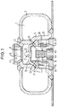
- Figure 1 the only drawing, shows a longitudinal section through an embodiment of the invention, as a hybrid gas generator trained gas generator.
- FIG 1 is a hybrid annulus gas generator for a Vehicle occupant restraint system, more specifically for inflating one Driver gas bags shown.
- the housing of the gas generator has one outer wall 3 and an inner spaced radially from it Wall 5 on. Between the walls is an annular one Pressure chamber 7 is formed, which is filled with compressed gas.
- the inner one Wall 5 separates the pressure chamber 7 from a radially inner space is divided into individual chambers.
- An upper one Outflow opening 9 adjacent mixing chamber 11 is through a Intermediate floor 13 separated from two lower chambers, namely one radially inner expansion chamber 15 into which an igniter 17 projects, and a radially outer annular combustion chamber 19.
- the combustion chamber 19 is filled with fuel in the form of tablets.
- detonator diffuser 21 The combustion chamber 19 and the expansion chamber 15 are through a cap-like diffuser, hereinafter referred to as detonator diffuser 21, separated from one another. Since none the chambers inside the housing are completely closed, there is the same pressure in each chamber.
- Several openings 23 in Igniter diffuser 21, openings 25 in the inner wall 5, one central axial opening 27 in the intermediate floor and two diametrically opposite, upper openings 29 serve in the inner wall 5 the pressure equalization and of course to the fact that the gas generated in Restraint case specifically reaches the outlet opening 9.
- the igniter 17 is gas and pressure tight on a closure part 31 in Forms a disk-shaped base plate attached and forms with this is a pre-assembled unit.
- the gas and pressure tight connection is achieved in that a detonator cap 33 made of metal, which the Surrounds primary and secondary charge of the igniter, preferably by Laser welding is attached to the closure part in a gastight and pressure-tight manner. A corresponding weld seam is marked with 35.
- the ignition material the secondary charge surrounding the primary charge immediately borders to the detonator cap 33.
- the detonator cap is cylindrical formed and has an end wall projecting into the expansion chamber 15 as well as a cylindrical jacket.
- the closure part 31 has on the inside i.e.
- the closure part 31 also has one outside recess 41, protrude into the plug contacts 43 of the igniter. However, the plug contacts 43 do not protrude from the closure part 31 to the outside, so that they do not when transporting the gas generator can be bent.
- the closure part 31 is used for gas-tight and pressure-tight closing of a filling opening 37 Filling opening 37 is filled with fuel in the combustion chamber 19. Then the closure part 31 is placed on the filling opening 37 set and welded to the housing. Eventually, a opposite filling opening for gas, which is already shown in FIG a closure in the form of a diffuser 41 with attached Rupture disc 43 is shown closed, filled with compressed gas Diffuser 41 attached and also welded to the housing.
- a trigger sensor activates the Igniter 17 so that the primary and secondary charge burn off and gas as well as generate hot particles.
- the detonator cap 33 is designed that its end wall, which faces the rupture disk 43, first opens and accompanies the gases and particles at high speed from a pressure wave, enter the expansion chamber 15 and itself distribute it evenly. Part of the pressure wave, the hot gases and particle hits directly through opening 27 on the rupture disc 43 and leads to their immediate destruction. The other part of the hot gases and particles gets through the Openings 23 in the combustion chamber 19, where they are used to ignite the fuel to lead. The gases generated when the fuel burns in turn flow through the openings 25 into the pressure chamber and mix with the compressed gas. The hot gas mixes with the cold compressed gas and burns afterwards.
Abstract
Description
Die Erfindung betrifft einen Gasgenerator, insbesondere für Fahrzeuginsassen-Rückhaltesysteme, mit einem Gehäuse mit wenigstens einer mit Gas gefüllten Kammer und wenigstens einer mit Treibstoff gefüllten Brennkammer, und mit wenigstens einem Zündmaterial aufweisenden Zünder zum Zünden des Treibstoffs, der eine Zünderkappe, die Zündmaterial einschließt, hat, wobei das Gehäuse ein Verschlußteil aufweist, welches eine Öffnung im übrigen Gehäuse verschließt.The invention relates to a gas generator, in particular for Vehicle occupant restraint systems, with a housing with at least a chamber filled with gas and at least one with fuel filled combustion chamber, and with at least one ignition material Detonator for igniting the fuel, which is a detonator cap Includes ignition material, the housing having a closure part has, which closes an opening in the rest of the housing.
Bei den mit Gas gefüllten Gasgeneratoren, insbesondere mit Druckgas gefüllten Hybrid-Gasgeneratoren, besteht das Problem, daß deren Gehäuse über Jahre hinweg druck- und gasdicht bleiben muß, damit das Gas nicht nach außen gelangt. Deshalb sind aufwendige Abdichtungsmaßnahmen erforderlich. Um einen Gasaustritt im Bereich des Zünders zu verhindern, wird deshalb bei den bisherigen Gasgeneratoren der Zünder in einer gas- und druckdichten Kammer angeordnet. Eine Berstmembrane, die üblicherweise die Stirnwand der Kammerwandung bildet, wird vom Zünder und gegebenenfalls von der angrenzenden Verstärkerladung zerstört, so daß die erzeugten heißen Gase und heißen Partikel in die angrenzende Brennkammer strömen können und dort den Brennstoff entzünden. Eine aufwendige Abdichtung ist beispielsweise in der DE 195 33 606 A1 gezeigt.In the case of gas generators filled with gas, in particular with compressed gas filled hybrid gas generators, there is the problem that their Housing must remain pressure and gas tight for years so that the Gas did not get outside. That is why there are complex sealing measures required. To allow gas to escape in the area of the igniter prevent, therefore, the igniter in the previous gas generators arranged in a gas and pressure-tight chamber. A burst membrane which usually forms the end wall of the chamber wall is from Detonator and possibly destroyed by the adjacent booster charge, so that the generated hot gases and hot particles in the adjacent combustion chamber can flow and there the fuel ignite. A complex seal is for example in the DE 195 33 606 A1 shown.
Die Erfindung schafft einen Gasgenerator, der einfacher aufgebaut ist als die bisher bekannten und kostengüngstig hergestellt werden kann. Dies wird bei einem Gasgenerator der eingangs genannten Art dadurch erreicht, daß die Zünderkappe am Verschlußteil durch Anschweißen gas- und druckdicht befestigt ist. Im Gegensatz zu den bekannten Gasgeneratoren ist eine separate, abgeschlossene Kammer für die Abdichtung des Zünders oder eine aufwendige Dichtung zwischen Zünderkappe und Verschlußteil nicht erforderlich. Die mit Gas gefüllte Kammer ist zudem zum Zünder hin offen. Ein Entweichen von Gas zwischen Zünder und Verschlußteil ist aufgrund der gas- und druckdichten Schweißverbindung ausgeschlossen. Beim Abbrennen des Zünders kann der Treibstoff zudem sehr schnell gezündet werden, da zwischen Zündmaterial und Treibstoff nur die sehr dünne Zünderkappe ist. Bislang wurde Schweißen in unmittelbarer Nähe von pyrotechnischem Material vermieden. Die Erfindung setzt sich bewußt hierüber hinweg.The invention provides a gas generator that is simpler in construction is known as the previously known and inexpensive to manufacture can. This is the case with a gas generator of the type mentioned at the outset achieved that the detonator cap on the closure part by welding is attached gas and pressure tight. In contrast to the known gas generators is a separate, sealed chamber for sealing the igniter or an elaborate seal between the igniter cap and closure part not required. The gas-filled chamber is also open to the detonator. A leak of gas between the igniter and The closure part is due to the gas and pressure-tight welded connection locked out. When the detonator burns, the fuel can also be ignited very quickly, because between the ignition material and the fuel only the very thin detonator cap is. So far, welding has been immediate Avoid proximity to pyrotechnic material. The invention deliberately ignores this.
Vorteilhafte Ausgestaltungen der Erfindung bilden die Gegenstände der Unteransprüche.The objects form advantageous embodiments of the invention of subclaims.
Gemäß der bevorzugten Ausführungsform ist die mit Gas gefüllte Kammer eine Druckkammer, deren Gas unter Druck steht und die zur Brennkammer hin offen ist.According to the preferred embodiment, the one is filled with gas Chamber is a pressure chamber, the gas is under pressure and the Combustion chamber is open.
Die gas- und druckdichte Abdichtung erfolgt vorzugsweise durch Laserschweißen.The gas and pressure-tight seal is preferably carried out by Laser welding.
Die Öffnung, auf die das Verschlußteil aufgesetzt wird, dient vorzugsweise zum Befüllen des Gasgenerators mit Treibstoff.The opening on which the closure part is placed serves preferably for filling the gas generator with fuel.
Weitere Merkmale und Vorteile der Erfindung ergeben sich aus der nachfolgenden Beschreibung und aus der nachfolgenden Zeichnung, auf die Bezug genommen wird. Further features and advantages of the invention result from the following description and from the following drawing which is referenced.
Figur 1, die einzige Zeichnung, zeigt einen Längsschnitt durch eine Ausführungsform des erfindungsgemäßen, als Hybrid-Gasgenerator ausgebildeten Gasgenerators.Figure 1, the only drawing, shows a longitudinal section through an embodiment of the invention, as a hybrid gas generator trained gas generator.
In Figur 1 ist ein Hybrid-Ringkammer-Gasgenerator für ein
Fahrzeuginsassen-Rückhaltesystem, genauer gesagt zum Aufblasen eines
Fahrer-Gassacks gezeigt. Das Gehäuse des Gasgenerators weist eine
äußere Wandung 3 und eine radial von dieser beabstandete innere
Wandung 5 auf. Zwischen den Wandungen ist eine ringförmig verlaufende
Druckkammer 7 gebildet, die mit Druckgas gefüllt ist. Die innere
Wandung 5 trennt die Druckkammer 7 von einem radial inneren Raum, der
in einzelne Kammern unterteilt ist. Eine obere, an eine
Ausströmöffnung 9 angrenzende Mischkammer 11 wird durch einen
Zwischenboden 13 von zwei unteren Kammern getrennt, nämlich einer
radial inneren Expansionskammer 15, in die ein Zünder 17 ragt, und
einer radial äußeren ringförmigen Brennkammer 19. Die Brennkammer 19
ist mit Treibstoff in Form von Tabletten gefüllt. Die Brennkammer 19
und die Expansionskammer 15 sind durch einen kappenartigen Diffusor,
im folgenden Zünderdiffusor 21 genannt, voneinander getrennt. Da keine
der Kammern im Inneren des Gehäuses vollständig abgeschlossen ist,
herrscht in jeder Kammer derselbe Druck. Mehrere Öffnungen 23 im
Zünderdiffusor 21, Öffnungen 25 in der inneren Wandung 5, eine
zentrale axiale Öffnung 27 im Zwischenboden sowie zwei diametral
gegenüberliegende, obere Öffnungen 29 in der inneren Wandung 5 dienen
dem Druckausgleich und natürlich dazu, daß das erzeugte Gas im
Rückhaltefall gezielt bis zur Austrittsöffnung 9 gelangt.In Figure 1 is a hybrid annulus gas generator for a
Vehicle occupant restraint system, more specifically for inflating one
Driver gas bags shown. The housing of the gas generator has one
outer wall 3 and an inner spaced radially from it
Wall 5 on. Between the walls is an annular one
Pressure chamber 7 is formed, which is filled with compressed gas. The inner one
Wall 5 separates the pressure chamber 7 from a radially inner space
is divided into individual chambers. An upper one
Outflow opening 9 adjacent mixing chamber 11 is through a
Der Zünder 17 ist gas- und druckdicht an einem Verschlußteil 31 in
Form einer scheibenförmigen Bodenplatte befestigt und bildet mit
dieser eine vormontierte Einheit. Die gas- und druckdichte Verbindung
wird dadurch erreicht, daß eine Zünderkappe 33 aus Metall, welche die
Primär- und die Sekundärladung des Zünders umgibt, vorzugsweise durch
Laserschweißen am Verschlußteil gas- und druckdicht befestigt ist.
Eine entsprechende Schweißnaht ist mit 35 gekennzeichnet. Das Zündmaterial
der die Primärladung umgebenden Sekundärladung grenzt unmittelbar
an die Zünderkappe 33 an. Die Zünderkappe ist zylindrisch
ausgebildet und hat eine in die Expansionskammer 15 ragende Stirnwand
sowie einen zylindrischen Mantel. Das Verschlußteil 31 hat innenseitig,
d.h. zur Expansionskammer 15 hin, eine kreisringförmige
Vertiefung, die in ihrer Geometrie und ihren Abmaßen der der
Zünderkappe 33 entspricht und in die die Zünderkappe vor dem
Anschweißen eingesteckt ist. Das Verschlußteil 31 hat auch eine
außenseitige Vertiefung 41, in die Steckkontakte 43 des Zünders ragen.
Die Steckkontakte 43 ragen aber nicht gegenüber dem Verschlußteil 31
nach außen vor, so daß sie beim Transport des Gasgenerators auch nicht
verbogen werden können. In die Vertiefung wird beim Einbau des
Gasgenerators ein Stecker eingesetzt. Das Verschlußteil 31 dient zum
gas- und druckdichten Verschließen einer Befüllöffnung 37. Über die
Befüllöffnung 37 wird Treibstoff in die Brennkammer 19 gefüllt.
Anschließend wird das Verschlußteil 31 auf die Befüllöffnung 37
gesetzt und am Gehäuse verschweißt. Schließlich wird über eine
gegenüberliegende Befüllöffnung für Gas, die in Figur 1 bereits durch
einen Verschluß in Form eines Diffusors 41 mit daran befestigter
Berstscheibe 43 verschlossen gezeigt ist, Druckgas eingefüllt, der
Diffusor 41 aufgesetzt und ebenfalls am Gehäuse verschweißt.The
Bei einem Unfall aktiviert eine nicht gezeigte Auslösesensorik den
Zünder 17, so daß die Primär- und die Sekundärladung abbrennen und Gas
sowie heiße Partikel erzeugen. Die Zünderkappe 33 ist so ausgebildet,
daß sich ihre Stirnwand, die der Berstscheibe 43 zugewandt ist, zuerst
öffnet und die Gase und Partikel mit großer Geschwindigkeit, begleitet
von einer Druckwelle, in die Expansionskammer 15 eintreten und sich
darin gleichmäßig verteilen. Ein Teil der Druckwelle, der heißen Gase
und Partikel trifft, durch die Öffnung 27 hindurchtretend, unmittelbar
auf die Berstscheibe 43 auf und führt zu deren sofortiger Zerstörung.
Der andere Teil der heißen Gase und Partikel gelangt über die
Öffnungen 23 in die Brennkammer 19, wo diese zur Zündung des Treibstoffs
führen. Die beim Abbrennen des Treibstoffs erzeugten Gase
wiederum strömen durch die Öffnungen 25 in die Druckkammer und
vermischen sich darin mit dem Druckgas. Das heiße Gas vermischt sich
mit dem kalten Druckgas und verbrennt dabei nach. Über die Öffnungen
29 strömen das Druckgas sowie das heiße Gas in die Mischkammer 11,
ebenso wie das heiße, über die Expansionskammer 15 in die Mischkammer
11 gelangende Gas, das beim Abbrennen des Treibstoffs entsteht. Auch
in der Mischkammer 11 reagieren die Gase chemisch miteinander. Die
Gase verlassen schließlich über den Diffusor 41 das Gehäuse. In an accident, a trigger sensor, not shown, activates the
Igniter 17 so that the primary and secondary charge burn off and gas
as well as generate hot particles. The
Da der Zünder 17 nicht noch zusätzlich von einer ihn umgebenden
Wandung zur Brennkammer 19 hin vollständig abgeschirmt ist, ergibt
sich ein schnelles Anzündverhalten. Der Expansionsraum 15 und der
Zünderdiffusor 21 bewirken ein gleichmäßiges Einströmen der heißen
Gase in die Brennkammer 19 und führen damit zu einem reproduzierbaren
Anzündverhalten, ohne daß eine leistungsstarke Boosterladung benutzt
werden muß.Since the
Claims (13)
Applications Claiming Priority (2)
| Application Number | Priority Date | Filing Date | Title |
|---|---|---|---|
| DE19723256 | 1997-06-03 | ||
| DE19723256A DE19723256A1 (en) | 1997-06-03 | 1997-06-03 | Gas generator |
Publications (1)
| Publication Number | Publication Date |
|---|---|
| EP0882629A1 true EP0882629A1 (en) | 1998-12-09 |
Family
ID=7831269
Family Applications (1)
| Application Number | Title | Priority Date | Filing Date |
|---|---|---|---|
| EP98110065A Withdrawn EP0882629A1 (en) | 1997-06-03 | 1998-06-03 | Gas generator |
Country Status (3)
| Country | Link |
|---|---|
| US (1) | US5957492A (en) |
| EP (1) | EP0882629A1 (en) |
| DE (1) | DE19723256A1 (en) |
Cited By (1)
| Publication number | Priority date | Publication date | Assignee | Title |
|---|---|---|---|---|
| EP2471692B2 (en) † | 2009-05-11 | 2022-01-05 | Joyson Safety Systems Germany GmbH | Gas generator for inflating a gas bag of a vehicle occupant restraint system and method of inflating a gas bag |
Families Citing this family (6)
| Publication number | Priority date | Publication date | Assignee | Title |
|---|---|---|---|---|
| DE19723260A1 (en) * | 1997-06-03 | 1998-12-10 | Temic Bayern Chem Airbag Gmbh | Gas generator |
| DE19723259A1 (en) * | 1997-06-03 | 1998-12-10 | Temic Bayern Chem Airbag Gmbh | Gas generator and method for operating a gas generator |
| DE20020103U1 (en) | 2000-11-27 | 2001-04-05 | Trw Airbag Sys Gmbh & Co Kg | Pyrotechnic gas generator |
| US6877435B2 (en) | 2002-09-12 | 2005-04-12 | Textron Systems Corporation | Dual-stage gas generator utilizing eco-friendly gas generant formulation |
| US6918340B2 (en) | 2002-09-12 | 2005-07-19 | Textron Systems Corporation | Dual-stage gas generator utilizing eco-friendly gas generant formulation for military applications |
| DE202004016556U1 (en) * | 2004-10-26 | 2005-03-17 | Trw Airbag Sys Gmbh | inflator |
Citations (6)
| Publication number | Priority date | Publication date | Assignee | Title |
|---|---|---|---|---|
| DE19533606A1 (en) | 1994-09-13 | 1996-03-14 | Trw Inc | Airbag inflator with pressure sensor |
| EP0741064A2 (en) * | 1995-05-02 | 1996-11-06 | Oea, Inc. | Method for manufacturing hybrid inflator having toroidal-like stored gas housing |
| US5609361A (en) * | 1995-08-24 | 1997-03-11 | Trw Vehicle Safety Systems Inc. | Inflation fluid container and initiator with press-fit fluid seal |
| US5630619A (en) * | 1996-02-28 | 1997-05-20 | Morton International, Inc. | Hybrid adaptive inflator for airbags |
| DE19601448A1 (en) * | 1996-01-17 | 1997-07-24 | Temic Bayern Chem Airbag Gmbh | Closure for a gas generator |
| WO1998009851A1 (en) * | 1996-09-09 | 1998-03-12 | Atlantic Research Corporation | A variable output driver side hybrid inflator |
Family Cites Families (7)
| Publication number | Priority date | Publication date | Assignee | Title |
|---|---|---|---|---|
| JPS4716498Y1 (en) * | 1970-04-25 | 1972-06-09 | ||
| DE2362513A1 (en) * | 1972-12-18 | 1974-07-04 | Aerojet General Co | DEVICE AND METHOD FOR GENERATING AND BLOWING OUT GAS |
| DE7422465U (en) * | 1973-07-05 | 1978-03-09 | Allied Chemical Corp., Morristown, N.J. (V.St.A.) | Device for inflating a motor vehicle safety device |
| US5100174A (en) * | 1990-12-18 | 1992-03-31 | Trw, Inc. | Auto ignition package for an air bag inflator |
| US5184846A (en) * | 1991-11-01 | 1993-02-09 | Trw Vehicle Safety Systems Inc. | Inflator assembly |
| KR0148835B1 (en) * | 1993-08-20 | 1998-10-15 | 제임스 엠. 루즈벨트 | Inflator assembly |
| US5762368A (en) * | 1996-06-20 | 1998-06-09 | Trw Vehicle Safety Systems Inc. | Initiator for air bag inflator |
-
1997
- 1997-06-03 DE DE19723256A patent/DE19723256A1/en not_active Withdrawn
-
1998
- 1998-06-03 US US09/089,655 patent/US5957492A/en not_active Expired - Fee Related
- 1998-06-03 EP EP98110065A patent/EP0882629A1/en not_active Withdrawn
Patent Citations (6)
| Publication number | Priority date | Publication date | Assignee | Title |
|---|---|---|---|---|
| DE19533606A1 (en) | 1994-09-13 | 1996-03-14 | Trw Inc | Airbag inflator with pressure sensor |
| EP0741064A2 (en) * | 1995-05-02 | 1996-11-06 | Oea, Inc. | Method for manufacturing hybrid inflator having toroidal-like stored gas housing |
| US5609361A (en) * | 1995-08-24 | 1997-03-11 | Trw Vehicle Safety Systems Inc. | Inflation fluid container and initiator with press-fit fluid seal |
| DE19601448A1 (en) * | 1996-01-17 | 1997-07-24 | Temic Bayern Chem Airbag Gmbh | Closure for a gas generator |
| US5630619A (en) * | 1996-02-28 | 1997-05-20 | Morton International, Inc. | Hybrid adaptive inflator for airbags |
| WO1998009851A1 (en) * | 1996-09-09 | 1998-03-12 | Atlantic Research Corporation | A variable output driver side hybrid inflator |
Cited By (1)
| Publication number | Priority date | Publication date | Assignee | Title |
|---|---|---|---|---|
| EP2471692B2 (en) † | 2009-05-11 | 2022-01-05 | Joyson Safety Systems Germany GmbH | Gas generator for inflating a gas bag of a vehicle occupant restraint system and method of inflating a gas bag |
Also Published As
| Publication number | Publication date |
|---|---|
| DE19723256A1 (en) | 1998-12-10 |
| US5957492A (en) | 1999-09-28 |
Similar Documents
| Publication | Publication Date | Title |
|---|---|---|
| DE19654315A1 (en) | Hybrid gas generator | |
| EP0704347B1 (en) | Gas generator | |
| DE19728438A1 (en) | Pyrotechnic gas generator | |
| WO1997008019A1 (en) | Device for filling a restraint device | |
| EP0882629A1 (en) | Gas generator | |
| DE112018002298T5 (en) | inflator | |
| EP0882628B1 (en) | Gas generator | |
| DE19725476A1 (en) | Gas generator | |
| DE112017001991T5 (en) | Gas generator | |
| EP0882627B1 (en) | Gas generator and method of operating a gas generator | |
| DE4138988A1 (en) | GAS GENERATOR, ESPECIALLY TUBE GAS GENERATOR FOR AN INFLATABLE IMPACT PROTECTION CUSHION | |
| EP1702815A2 (en) | Cold gas generator | |
| DE19541924A1 (en) | Two stage gas generator for vehicle occupant safety airbag | |
| DE69731688T2 (en) | GAS GENERATOR DEVICE FOR ONE AIR BAG | |
| DE19701663B4 (en) | inflator | |
| DE19635637A1 (en) | Hybrid gas generator | |
| DE19725475A1 (en) | Gas generator | |
| DE19631314B4 (en) | Hybrid gas generator | |
| DE102018119084A1 (en) | Deflector component, gas generator, gas bag module, vehicle safety system and method for operating a gas generator | |
| DE19723257A1 (en) | Hybrid gas generator for vehicle airbag system | |
| DE19529553A1 (en) | Arrangement for opening the bursting membrane of compressed gas cylinders in gas generators | |
| DE19631315A1 (en) | Hybrid gas generator | |
| DE19631316B4 (en) | Hybrid gas generator | |
| DE19723258A1 (en) | Gas generator for vehicle airbag safety system | |
| DE19726598A1 (en) | Hybrid gas generator, particularly for vehicle occupant retention system |
Legal Events
| Date | Code | Title | Description |
|---|---|---|---|
| PUAI | Public reference made under article 153(3) epc to a published international application that has entered the european phase |
Free format text: ORIGINAL CODE: 0009012 |
|
| AK | Designated contracting states |
Kind code of ref document: A1 Designated state(s): DE FR IT NL |
|
| AX | Request for extension of the european patent |
Free format text: AL;LT;LV;MK;RO;SI |
|
| 17P | Request for examination filed |
Effective date: 19990609 |
|
| AKX | Designation fees paid |
Free format text: DE FR IT NL |
|
| 17Q | First examination report despatched |
Effective date: 20001016 |
|
| STAA | Information on the status of an ep patent application or granted ep patent |
Free format text: STATUS: THE APPLICATION IS DEEMED TO BE WITHDRAWN |
|
| 18D | Application deemed to be withdrawn |
Effective date: 20010427 |