EP0882530A2 - Verfahren zur Kaltformgebung eines Rohrendes als Doppeltwand durch Umstülpen der ersten Endstückwand - Google Patents
Verfahren zur Kaltformgebung eines Rohrendes als Doppeltwand durch Umstülpen der ersten Endstückwand Download PDFInfo
- Publication number
- EP0882530A2 EP0882530A2 EP98440119A EP98440119A EP0882530A2 EP 0882530 A2 EP0882530 A2 EP 0882530A2 EP 98440119 A EP98440119 A EP 98440119A EP 98440119 A EP98440119 A EP 98440119A EP 0882530 A2 EP0882530 A2 EP 0882530A2
- Authority
- EP
- European Patent Office
- Prior art keywords
- tube
- wall
- conformation
- edge
- lateral surface
- Prior art date
- Legal status (The legal status is an assumption and is not a legal conclusion. Google has not performed a legal analysis and makes no representation as to the accuracy of the status listed.)
- Withdrawn
Links
Images


Classifications
-
- B—PERFORMING OPERATIONS; TRANSPORTING
- B21—MECHANICAL METAL-WORKING WITHOUT ESSENTIALLY REMOVING MATERIAL; PUNCHING METAL
- B21D—WORKING OR PROCESSING OF SHEET METAL OR METAL TUBES, RODS OR PROFILES WITHOUT ESSENTIALLY REMOVING MATERIAL; PUNCHING METAL
- B21D19/00—Flanging or other edge treatment, e.g. of tubes
- B21D19/16—Reverse flanging of tube ends
Definitions
- Lining also provides protection additional from the inner part of the end, and thereby guarantees greater mechanical strength vibration and corrosion of this part and therefore contributes greatly to the maintenance of assembly and its tightness over time.
- the object of the present invention is to obtain by a single cold forming process on a single machine strengthening the end of a tube metallic by creating a double wall from rolling up its end.
- the invention relates to a process of cold conformation of the end of a metal tube to strengthen it with a second wall, characterized in that a rolled edge is formed at the end of the tube by shaping it in a tool embossing with annular recess, which is continued by pushed the forming movement to birth a wall parallel to the lateral surface of the tube, that we increase the length of this wall by push to the desired length and proceed when the formed wall approaches the surface lateral of the end by at least two passages to using a spinning tool and which we comply the double-walled end to give it shape technique adapted to its use.
- the embossing tool 2 has a front before 3 and has in its thickness an obviously annular 4 shaped into an annular groove 5, the inner diameter is approximately the diameter inside of the end 6 of the tube and whose diameter outside corresponds approximately to the outside diameter from the double-walled end before the tightening of this wall around the adjacent side surface of the tube, as will be seen below.
- the profile of this annular groove 5 affects the general shape of an arch 7 with curvilinear profile including the central part 8 at the bottom groove 9 is substantially circular.
- the radius of curvature of this central part 8 depends on the thickness of the metal and its physical characteristics and properties.
- the annular groove defines a flat cylinder central with flared base. It presents on the face opposite a slightly profiled clearance zone oblique.
- metals too malleable or ductile such as copper, aluminum, zinc and the like are not suitable.
- Non-limiting typical examples are: steels and their alloys and metals and alloys of metal having similar characteristics.
- Tube 1 is held tight in a holder fixed and the pushing tool 2 is forced longitudinally against the end 6 of the tube.
- the end 6 of the tube gradually flares by its progression over the curvature of the surface of the annular groove 5 after have been guided along the central block 10 in shape flat cylinder 11 with diverging rounded base, cylinder flat 11 delimited in the central space by the recess 4 in annular groove 5.
- this annular groove 5 of general arch profile with central part 8 substantially circular has a slight clearance oblique 12 at exit.
- the peripheral end region of the tube flares out in the shape of a cone 13 until turned over by a rounded rounded edge 14 at the bottom 9 of the groove.
- the rolled edge 14 keeps its curvature at the exit of the groove and progresses as shown in the figures until a certain distance from the lateral surface 15 of the tube.
- the stop of the rolled edge progression 14 towards the tube 1 takes place at a certain distance "d" of it, for example up to an interval of a few millimeters in the case of common tubes used for car exhaust pipes automobiles with diameters of the order of 4 to 5 cm.
- This remote stop “d” results from mechanical characteristics according to which the edge rolled 14 opposes the continuation of rolling when it has reached a certain shape and when the diameter of the circle delimited by its peripheral edge reaches a minimum value corresponding to its limit compression. A force opposes the constriction extra because the material cannot contract more.
- the second main phase of the process consists in folding this double wall against the tube.
- One way to do this is to bind off by spinning, that is to say by practicing a shrunk in diameter using, successively one after the other, several adapted pieces of lower diameter that we slide along the double wall.
- Each spinning piece has an inlet cone more or less important depending on the reduction to be obtained.
- the spinning passages push the material along the tube, bring it closer to the tube and form a tapered end 21 after the first pass which comes from the entry into cone 18 of the first tool wiring 17 which stops at the end of the second wall 16.
- the rolled edge 14 is found slightly deformed at the end into a cone 21.
- the latest spinning tool 19 presses completely the material of the outer wall against the side surface wall 15 and folds down the cone end 21 against this wall and crush the rolled edge 14 on itself as it appears on the Figures 12 and 13 thus forming a rigid border 22 in double thickness.
- a form in bowl 26 as shown obtained by a method of burnishing using inclined rollers 27 and 28 or other process which serves as a seat at a conical end in view of a push-in or end connection spherical for the realization of a joint patella.
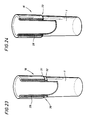
- a more aesthetic alternative is to extend the upturned end beyond the sleeve reinforcement 29 by different methods, either by later inserting it under the lining of rolling up 16, either by counteracting its sliding down, either by providing a wider spacing between the body of the tube and the roll-up lining 16, or by any other appropriate means.
- Figure 24 is intended to show the result thus obtained by this second method.
- the closing of the lower edge is clean and aesthetic by a single bottom border 33.
- Figures 25 to 31 show so details of the important variant of the process which consists in making the lining of roll up no longer towards the outside but towards the interior.
- This variant takes up the main phases of the basic process described below.
- the hollow tool of embossing 34 has a front edge and comprises in its thickness an annular groove recess 35 of which the outside diameter corresponds substantially to outer diameter of the tube and whose diameter interior also corresponds substantially to the diameter inside of the roll-up lining 36 before its tightening against the inner side surface of the end of the tube.
- this annular groove 35 affects the general shape of an arch with a curvilinear profile, the general layout approximates that of an arc of circle.
- the shape's shape is reproduced on the figure 31.
- the shape of this line depends on the thickness of the metal and its characteristics and properties physical.
- the route breaks down into three parts.
- the first part A is a segment in an arc flared
- the final part B is a drawdown zone and clearance profile in an arc of a contracted circle
- the intermediate part C is a central area curved substantially circular connection.
- Tube 1 is held tight in the holder fixed of a machine and the embossing tool 34 is forced longitudinally using a pushing means for example with hydraulic cylinder against the end of the tube. Conversely, the tube 1 can be forced against the embossing tool 34 by the same means of thrust for example hydraulic.
- the cold conformation process in its inside lining variant 36 takes place according to the steps shown in Figures 25 to 30.
- the end of tube 1 gradually flares by its progression over the curvature of the surface of the annular groove 35 after having been guided along the part A of the profile of this groove.
- the peripheral end zone of the tube contracts in cone shape until overturned by a rounded rounded edge 37 at the bottom of throat.
- the rolled edge 37 retains its curvature at the outlet throat and progress as shown in the figures up to a certain distance from the surface inner side of the tube.
- the halting of the rolled edge progression 37 towards the tube 1 takes place at a certain distance from this one, for example up to an interval of a few millimeters in the case of common tubes used for the exhaust manifold of motor cars including the diameter is of the order of 4 to 5 cm.
- This remote stop results from mechanical characteristics according to which the edge rolled 37 opposes the continuation of rolling when it has reached a certain shape and when the diameter of the circle delimited by its peripheral edge reaches a maximum value corresponding to its limit extension and compression. A force opposes the additional extension because the material cannot expand further.
- the second main phase of the process consists in folding down this inner double wall 36 against the inside of the tube.
- One way to do this is to fold back by mandrel in one, but preferably in two passes, the first by a mandrel primary 38 and the second by an adjusted mandrel 39.
- the result is a smooth interior double wall 36 and pressed against the inner lateral face of the tube, as shown in figure 32 delimited downwards by a flat edge 40 against the side face inside the tube and upwards by the rounded edge 41 end of the tube.
- the end of the tube is thus reinforced by invisible lining from the outside.
- This end can be shaped later depending on the applications in a flare 42 (figure 34) or a narrowing 43 (figure 35) which can go until total closure.
- Rolling inward presents many advantages. It is more user-friendly and economic. The presentation is immediately aesthetic and above all, it prevents the deposition and introduction of moisture in the lining that was previously at outside.
Applications Claiming Priority (2)
| Application Number | Priority Date | Filing Date | Title |
|---|---|---|---|
| FR9707206 | 1997-06-06 | ||
| FR9707206A FR2764217B1 (fr) | 1997-06-06 | 1997-06-06 | Procede de conformation a froid de l'extremite d'un tube metallique a simple paroi a une extremite a double paroi |
Publications (2)
| Publication Number | Publication Date |
|---|---|
| EP0882530A2 true EP0882530A2 (de) | 1998-12-09 |
| EP0882530A3 EP0882530A3 (de) | 1999-07-07 |
Family
ID=9507833
Family Applications (1)
| Application Number | Title | Priority Date | Filing Date |
|---|---|---|---|
| EP98440119A Withdrawn EP0882530A3 (de) | 1997-06-06 | 1998-06-05 | Verfahren zur Kaltformgebung eines Rohrendes als Doppeltwand durch Umstülpen der ersten Endstückwand |
Country Status (2)
| Country | Link |
|---|---|
| EP (1) | EP0882530A3 (de) |
| FR (1) | FR2764217B1 (de) |
Cited By (7)
| Publication number | Priority date | Publication date | Assignee | Title |
|---|---|---|---|---|
| WO1999025967A1 (de) * | 1997-11-18 | 1999-05-27 | Zeuna-Stärker GmbH & Co. KG | Metallisches rohr |
| FR2911942A1 (fr) * | 2007-01-29 | 2008-08-01 | Legris Sa | Procede de raccordement par soudage far friction d'un element et d'une extremite retournee d'un tube multicouche |
| EP2974807A1 (de) | 2014-07-18 | 2016-01-20 | Modulo S.R.L. | Verfahren und vorrichtung zur herstellung eines abgasendabschnitts für vakuumabführsysteme für verbrannte gase von verbrennungsmotoren |
| WO2016082839A1 (en) * | 2014-11-28 | 2016-06-02 | Værktøjsfabrikken Paw V/Helene Nedergaard | Method for final forming of an open end of a pipe in one set-up and an apparatus con-figured to carry out the method |
| WO2016126218A1 (en) * | 2015-02-02 | 2016-08-11 | Dora Makina Imalat San. Ve Tic. Ltd. Sti | A bending system and method |
| CN112879143A (zh) * | 2019-11-29 | 2021-06-01 | 佛吉亚排气系统有限公司 | 通过同心翻卷加厚的管 |
| CN116020950A (zh) * | 2023-03-16 | 2023-04-28 | 安溪藤铁家居工业设计研究院有限公司 | 一种空心藤铁管口的扩口装置 |
Citations (3)
| Publication number | Priority date | Publication date | Assignee | Title |
|---|---|---|---|---|
| DE553403C (de) * | 1930-10-25 | 1932-07-20 | Rohrbogenwerk G M B H | Verfahren zum Aufweiten von Rohren |
| DE641038C (de) * | 1931-10-01 | 1937-01-18 | Roehrenwerke Akt Ges Deutsche | Vorrichtung zur Herstellung von bis zur Anlage an die Rohraussenwand umgeboerdelten gedoppelten Rohrenden |
| DE3422040A1 (de) * | 1984-06-14 | 1985-12-19 | Heinz-Eckhard Dipl.-Ing. 6100 Darmstadt Engel | Stuelp-umformverfahren zur herstellung von doppelwandigen zylindrischen werkstuecken sowie umformwerkzeug hierfuer |
Family Cites Families (1)
| Publication number | Priority date | Publication date | Assignee | Title |
|---|---|---|---|---|
| SU837478A1 (ru) * | 1979-09-19 | 1981-06-15 | Краматорский Индустриальный Институт | Способ изготовлени трубчатойзАгОТОВКи ВыВОРОТОМ |
-
1997
- 1997-06-06 FR FR9707206A patent/FR2764217B1/fr not_active Expired - Fee Related
-
1998
- 1998-06-05 EP EP98440119A patent/EP0882530A3/de not_active Withdrawn
Patent Citations (3)
| Publication number | Priority date | Publication date | Assignee | Title |
|---|---|---|---|---|
| DE553403C (de) * | 1930-10-25 | 1932-07-20 | Rohrbogenwerk G M B H | Verfahren zum Aufweiten von Rohren |
| DE641038C (de) * | 1931-10-01 | 1937-01-18 | Roehrenwerke Akt Ges Deutsche | Vorrichtung zur Herstellung von bis zur Anlage an die Rohraussenwand umgeboerdelten gedoppelten Rohrenden |
| DE3422040A1 (de) * | 1984-06-14 | 1985-12-19 | Heinz-Eckhard Dipl.-Ing. 6100 Darmstadt Engel | Stuelp-umformverfahren zur herstellung von doppelwandigen zylindrischen werkstuecken sowie umformwerkzeug hierfuer |
Non-Patent Citations (1)
| Title |
|---|
| SOVIET INVENTIONS ILLUSTRATED Section Ch, Week 821419 mai 1982 Derwent Publications Ltd., London, GB; Class M21, AN 82-28178e XP002055829 & SU 837 478 A (KRAMA IND INST) , 20 juin 1981 * |
Cited By (10)
| Publication number | Priority date | Publication date | Assignee | Title |
|---|---|---|---|---|
| WO1999025967A1 (de) * | 1997-11-18 | 1999-05-27 | Zeuna-Stärker GmbH & Co. KG | Metallisches rohr |
| FR2911942A1 (fr) * | 2007-01-29 | 2008-08-01 | Legris Sa | Procede de raccordement par soudage far friction d'un element et d'une extremite retournee d'un tube multicouche |
| WO2008096060A2 (fr) * | 2007-01-29 | 2008-08-14 | Legris Sas | Procede de raccordement par soudage par friction d ' un tube |
| WO2008096060A3 (fr) * | 2007-01-29 | 2008-10-09 | Legris Sa | Procede de raccordement par soudage par friction d ' un tube |
| EP2974807A1 (de) | 2014-07-18 | 2016-01-20 | Modulo S.R.L. | Verfahren und vorrichtung zur herstellung eines abgasendabschnitts für vakuumabführsysteme für verbrannte gase von verbrennungsmotoren |
| WO2016082839A1 (en) * | 2014-11-28 | 2016-06-02 | Værktøjsfabrikken Paw V/Helene Nedergaard | Method for final forming of an open end of a pipe in one set-up and an apparatus con-figured to carry out the method |
| DK178550B1 (en) * | 2014-11-28 | 2016-06-13 | Værktøjsfabrikken Paw V/Helene Nedergaard | Method for final forming of an open end of a pipe in one set-up and an apparatus configured to carry out the method |
| WO2016126218A1 (en) * | 2015-02-02 | 2016-08-11 | Dora Makina Imalat San. Ve Tic. Ltd. Sti | A bending system and method |
| CN112879143A (zh) * | 2019-11-29 | 2021-06-01 | 佛吉亚排气系统有限公司 | 通过同心翻卷加厚的管 |
| CN116020950A (zh) * | 2023-03-16 | 2023-04-28 | 安溪藤铁家居工业设计研究院有限公司 | 一种空心藤铁管口的扩口装置 |
Also Published As
| Publication number | Publication date |
|---|---|
| FR2764217B1 (fr) | 1999-10-22 |
| EP0882530A3 (de) | 1999-07-07 |
| FR2764217A1 (fr) | 1998-12-11 |
Similar Documents
| Publication | Publication Date | Title |
|---|---|---|
| FR2728816A1 (fr) | Procede pour former un element d'arbre et de fourchette monobloc a partir d'un flan de tubage ayant une section transversale generalement circulaire | |
| CH217289A (fr) | Procédé pour la fabrication de tubes flexibles à ondulations, machine pour la mise en oeuvre de ce procédé et tube obtenu par ce procédé. | |
| EP0882530A2 (de) | Verfahren zur Kaltformgebung eines Rohrendes als Doppeltwand durch Umstülpen der ersten Endstückwand | |
| EP0056776B1 (de) | Verfahren zur Herstellung von hohlen, einteiligen Achsrohlingen und erzeugte Achsrohlinge | |
| FR2731927A1 (fr) | Procede de fabrication d'une boite metallique de forme | |
| FR2604932A1 (fr) | Procede pour fabriquer des tubes en metal a paroi mince | |
| EP1299251B1 (de) | Fahrzeugrad mit montage unter dem felgensitz | |
| EP0099311A1 (de) | Lenkungszahnstange für Kraftfahrzeuge und Prozess zur Herstellung der Zahnstange | |
| WO2006110190A2 (en) | Tow hitch receiver | |
| CA2172227A1 (fr) | Procede de fabrication d'une boite metallique de forme | |
| FR2496511A1 (fr) | Procede de realisation de renforcements locaux de paroi laterale sur des corps creux | |
| FR2544806A1 (fr) | Procede d'assemblage de deux pieces de revolution coaxiales, de meme diametre | |
| EP0839593B1 (de) | Verfahren zum Herstellen eines Hohlrevolutionskörpers durch Fliessdrehen | |
| WO2014135772A1 (fr) | Outil pour former une collerette a une extremite d'un tube | |
| FR2698303A1 (fr) | Procédé de frettage d'au moins une pièce métallique ayant un alésage annulaire autour d'un tube métallique, ensemble obtenu et utilisation du procédé. | |
| FR2473916A1 (fr) | Procede de faconnage a froid d'un arbre tubulaire dont les extremites ont un diametre interieur calibre inferieur a celui de sa partie centrale | |
| US1165421A (en) | Making spouts. | |
| CH637746A5 (fr) | Tuyau en fonte ductile a emboitement. | |
| EP1192016A1 (de) | Verbindungsverfahren von minimal zwei metallischen bauteilen zur herstellung einer struktur | |
| CH632427A5 (fr) | Procede de formage d'une coque monobloc allongee avec une paroi laterale mince. | |
| CA3020410A1 (en) | Method and apparatus for producing a rolled curl on an open end of metal container | |
| EP0743111A1 (de) | Verfahren zur Herstellung eines Fütterungsgitterhebels, ein dadurch hergestellter Hebel und ein Futterungsgitter mit einem solchen Hebel | |
| FR2855198A1 (fr) | Organe d'evacuation des eaux pluviales et son procede d'obtention | |
| FR2652773A1 (fr) | Procede d'obtention d'une douille a collerette, notamment destinee a la liaison d'un tuyau sur un raccord, et dispositif pour sa mise en óoeuvre. | |
| FR2803780A1 (fr) | Procede de realisation d'une bonde d'un fut metallique |
Legal Events
| Date | Code | Title | Description |
|---|---|---|---|
| PUAI | Public reference made under article 153(3) epc to a published international application that has entered the european phase |
Free format text: ORIGINAL CODE: 0009012 |
|
| AK | Designated contracting states |
Kind code of ref document: A2 Designated state(s): AT DE ES FR GB IT |
|
| AX | Request for extension of the european patent |
Free format text: AL;LT;LV;MK;RO;SI |
|
| PUAL | Search report despatched |
Free format text: ORIGINAL CODE: 0009013 |
|
| AK | Designated contracting states |
Kind code of ref document: A3 Designated state(s): AT BE CH CY DE DK ES FI FR GB GR IE IT LI LU MC NL PT SE |
|
| AX | Request for extension of the european patent |
Free format text: AL;LT;LV;MK;RO;SI |
|
| 17P | Request for examination filed |
Effective date: 19990911 |
|
| AKX | Designation fees paid |
Free format text: AT DE ES FR GB IT |
|
| STAA | Information on the status of an ep patent application or granted ep patent |
Free format text: STATUS: THE APPLICATION IS DEEMED TO BE WITHDRAWN |
|
| 18D | Application deemed to be withdrawn |
Effective date: 20010103 |