EP0882484B1 - Oxygen concentrator with adsorption beds' duty cycle control and self-test - Google Patents
Oxygen concentrator with adsorption beds' duty cycle control and self-test Download PDFInfo
- Publication number
- EP0882484B1 EP0882484B1 EP98107180A EP98107180A EP0882484B1 EP 0882484 B1 EP0882484 B1 EP 0882484B1 EP 98107180 A EP98107180 A EP 98107180A EP 98107180 A EP98107180 A EP 98107180A EP 0882484 B1 EP0882484 B1 EP 0882484B1
- Authority
- EP
- European Patent Office
- Prior art keywords
- molecular sieve
- oxygen
- bed
- time period
- bed2
- Prior art date
- Legal status (The legal status is an assumption and is not a legal conclusion. Google has not performed a legal analysis and makes no representation as to the accuracy of the status listed.)
- Expired - Lifetime
Links
- QVGXLLKOCUKJST-UHFFFAOYSA-N atomic oxygen Chemical compound [O] QVGXLLKOCUKJST-UHFFFAOYSA-N 0.000 title claims description 134
- 239000001301 oxygen Substances 0.000 title claims description 134
- 229910052760 oxygen Inorganic materials 0.000 title claims description 134
- 238000012360 testing method Methods 0.000 title claims description 39
- 238000001179 sorption measurement Methods 0.000 title description 13
- 239000002808 molecular sieve Substances 0.000 claims description 71
- URGAHOPLAPQHLN-UHFFFAOYSA-N sodium aluminosilicate Chemical compound [Na+].[Al+3].[O-][Si]([O-])=O.[O-][Si]([O-])=O URGAHOPLAPQHLN-UHFFFAOYSA-N 0.000 claims description 71
- 239000007789 gas Substances 0.000 claims description 50
- 239000003570 air Substances 0.000 claims description 47
- 238000011010 flushing procedure Methods 0.000 claims description 29
- 238000000034 method Methods 0.000 claims description 24
- XLYOFNOQVPJJNP-UHFFFAOYSA-N water Substances O XLYOFNOQVPJJNP-UHFFFAOYSA-N 0.000 claims description 18
- 238000010926 purge Methods 0.000 claims description 17
- 230000000593 degrading effect Effects 0.000 claims description 4
- 230000003213 activating effect Effects 0.000 claims description 3
- 239000012080 ambient air Substances 0.000 claims description 3
- 230000007257 malfunction Effects 0.000 claims 2
- 230000008569 process Effects 0.000 description 12
- IJGRMHOSHXDMSA-UHFFFAOYSA-N Atomic nitrogen Chemical compound N#N IJGRMHOSHXDMSA-UHFFFAOYSA-N 0.000 description 10
- 230000000881 depressing effect Effects 0.000 description 6
- 101100457678 Saccharomyces cerevisiae (strain ATCC 204508 / S288c) MNN10 gene Proteins 0.000 description 5
- 230000001276 controlling effect Effects 0.000 description 5
- 238000003795 desorption Methods 0.000 description 5
- 238000012423 maintenance Methods 0.000 description 5
- 238000012544 monitoring process Methods 0.000 description 5
- 229910052757 nitrogen Inorganic materials 0.000 description 5
- 230000029058 respiratory gaseous exchange Effects 0.000 description 5
- 238000010586 diagram Methods 0.000 description 4
- 230000001965 increasing effect Effects 0.000 description 4
- 239000000203 mixture Substances 0.000 description 4
- 230000008929 regeneration Effects 0.000 description 4
- 238000011069 regeneration method Methods 0.000 description 4
- 102100023882 Endoribonuclease ZC3H12A Human genes 0.000 description 3
- 101710112715 Endoribonuclease ZC3H12A Proteins 0.000 description 3
- 230000009471 action Effects 0.000 description 3
- 238000011109 contamination Methods 0.000 description 3
- QGVYYLZOAMMKAH-UHFFFAOYSA-N pegnivacogin Chemical compound COCCOC(=O)NCCCCC(NC(=O)OCCOC)C(=O)NCCCCCCOP(=O)(O)O QGVYYLZOAMMKAH-UHFFFAOYSA-N 0.000 description 3
- 238000011056 performance test Methods 0.000 description 3
- 230000001105 regulatory effect Effects 0.000 description 3
- MYMOFIZGZYHOMD-UHFFFAOYSA-N Dioxygen Chemical compound O=O MYMOFIZGZYHOMD-UHFFFAOYSA-N 0.000 description 2
- 101000833492 Homo sapiens Jouberin Proteins 0.000 description 2
- 101000651236 Homo sapiens NCK-interacting protein with SH3 domain Proteins 0.000 description 2
- 102100024407 Jouberin Human genes 0.000 description 2
- 101710159752 Poly(3-hydroxyalkanoate) polymerase subunit PhaE Proteins 0.000 description 2
- 101710130262 Probable Vpr-like protein Proteins 0.000 description 2
- 208000007123 Pulmonary Atelectasis Diseases 0.000 description 2
- 230000004913 activation Effects 0.000 description 2
- 230000008859 change Effects 0.000 description 2
- 230000001143 conditioned effect Effects 0.000 description 2
- 239000000356 contaminant Substances 0.000 description 2
- 230000001351 cycling effect Effects 0.000 description 2
- HHNFORCFJOVQNF-UHFFFAOYSA-N cyl-1 Chemical compound N1C(=O)C(CCCCCC(=O)C2OC2)NC(=O)C2CCCN2C(=O)C(C(C)CC)NC(=O)C1CC1=CC=C(OC)C=C1 HHNFORCFJOVQNF-UHFFFAOYSA-N 0.000 description 2
- 230000003247 decreasing effect Effects 0.000 description 2
- 230000001419 dependent effect Effects 0.000 description 2
- 230000000994 depressogenic effect Effects 0.000 description 2
- 230000000694 effects Effects 0.000 description 2
- 239000012535 impurity Substances 0.000 description 2
- 239000007788 liquid Substances 0.000 description 2
- 210000004072 lung Anatomy 0.000 description 2
- 238000004519 manufacturing process Methods 0.000 description 2
- 238000003825 pressing Methods 0.000 description 2
- 230000004044 response Effects 0.000 description 2
- 230000002441 reversible effect Effects 0.000 description 2
- 229920006395 saturated elastomer Polymers 0.000 description 2
- 238000000926 separation method Methods 0.000 description 2
- 238000011144 upstream manufacturing Methods 0.000 description 2
- 238000012795 verification Methods 0.000 description 2
- WANLLPADDCXPGO-WMKJBNATSA-N (6r,9s,12s)-3-[(2s)-butan-2-yl]-6-[(4-methoxyphenyl)methyl]-9-[6-(oxiran-2-yl)-6-oxohexyl]-1,4,7,10-tetrazabicyclo[10.4.0]hexadecane-2,5,8,11-tetrone Chemical compound C([C@@H]1C(=O)NC(C(N2CCCC[C@H]2C(=O)N[C@@H](CCCCCC(=O)C2OC2)C(=O)N1)=O)[C@@H](C)CC)C1=CC=C(OC)C=C1 WANLLPADDCXPGO-WMKJBNATSA-N 0.000 description 1
- 101000768957 Acholeplasma phage L2 Uncharacterized 37.2 kDa protein Proteins 0.000 description 1
- 101000823746 Acidianus ambivalens Uncharacterized 17.7 kDa protein in bps2 3'region Proteins 0.000 description 1
- 101000916369 Acidianus ambivalens Uncharacterized protein in sor 5'region Proteins 0.000 description 1
- 101000769342 Acinetobacter guillouiae Uncharacterized protein in rpoN-murA intergenic region Proteins 0.000 description 1
- 101000823696 Actinobacillus pleuropneumoniae Uncharacterized glycosyltransferase in aroQ 3'region Proteins 0.000 description 1
- 101000786513 Agrobacterium tumefaciens (strain 15955) Uncharacterized protein outside the virF region Proteins 0.000 description 1
- 101000618005 Alkalihalobacillus pseudofirmus (strain ATCC BAA-2126 / JCM 17055 / OF4) Uncharacterized protein BpOF4_00885 Proteins 0.000 description 1
- 102100020724 Ankyrin repeat, SAM and basic leucine zipper domain-containing protein 1 Human genes 0.000 description 1
- 101100117391 Arabidopsis thaliana DPB2 gene Proteins 0.000 description 1
- 101100025691 Arabidopsis thaliana NAGLU gene Proteins 0.000 description 1
- 101000967489 Azorhizobium caulinodans (strain ATCC 43989 / DSM 5975 / JCM 20966 / LMG 6465 / NBRC 14845 / NCIMB 13405 / ORS 571) Uncharacterized protein AZC_3924 Proteins 0.000 description 1
- 101000823761 Bacillus licheniformis Uncharacterized 9.4 kDa protein in flaL 3'region Proteins 0.000 description 1
- 101000819719 Bacillus methanolicus Uncharacterized N-acetyltransferase in lysA 3'region Proteins 0.000 description 1
- 101000789586 Bacillus subtilis (strain 168) UPF0702 transmembrane protein YkjA Proteins 0.000 description 1
- 101000792624 Bacillus subtilis (strain 168) Uncharacterized protein YbxH Proteins 0.000 description 1
- 101000790792 Bacillus subtilis (strain 168) Uncharacterized protein YckC Proteins 0.000 description 1
- 101000819705 Bacillus subtilis (strain 168) Uncharacterized protein YlxR Proteins 0.000 description 1
- 101000948218 Bacillus subtilis (strain 168) Uncharacterized protein YtxJ Proteins 0.000 description 1
- 101000718627 Bacillus thuringiensis subsp. kurstaki Putative RNA polymerase sigma-G factor Proteins 0.000 description 1
- 101000641200 Bombyx mori densovirus Putative non-structural protein Proteins 0.000 description 1
- 101150020445 CYLC1 gene Proteins 0.000 description 1
- 101150080636 CYLC2 gene Proteins 0.000 description 1
- 101000947633 Claviceps purpurea Uncharacterized 13.8 kDa protein Proteins 0.000 description 1
- WANLLPADDCXPGO-UHFFFAOYSA-N Cyl-2 Natural products N1C(=O)C(CCCCCC(=O)C2OC2)NC(=O)C2CCCCN2C(=O)C(C(C)CC)NC(=O)C1CC1=CC=C(OC)C=C1 WANLLPADDCXPGO-UHFFFAOYSA-N 0.000 description 1
- 102100036233 Cylicin-1 Human genes 0.000 description 1
- 102100024257 Cylicin-2 Human genes 0.000 description 1
- 101000948901 Enterobacteria phage T4 Uncharacterized 16.0 kDa protein in segB-ipI intergenic region Proteins 0.000 description 1
- 101000805958 Equine herpesvirus 4 (strain 1942) Virion protein US10 homolog Proteins 0.000 description 1
- 101000790442 Escherichia coli Insertion element IS2 uncharacterized 11.1 kDa protein Proteins 0.000 description 1
- 101000788354 Escherichia phage P2 Uncharacterized 8.2 kDa protein in gpA 5'region Proteins 0.000 description 1
- 101000770304 Frankia alni UPF0460 protein in nifX-nifW intergenic region Proteins 0.000 description 1
- 101000797344 Geobacillus stearothermophilus Putative tRNA (cytidine(34)-2'-O)-methyltransferase Proteins 0.000 description 1
- 101000748410 Geobacillus stearothermophilus Uncharacterized protein in fumA 3'region Proteins 0.000 description 1
- 101000772675 Haemophilus influenzae (strain ATCC 51907 / DSM 11121 / KW20 / Rd) UPF0438 protein HI_0847 Proteins 0.000 description 1
- 101000631019 Haemophilus influenzae (strain ATCC 51907 / DSM 11121 / KW20 / Rd) Uncharacterized protein HI_0350 Proteins 0.000 description 1
- 101000768938 Haemophilus phage HP1 (strain HP1c1) Uncharacterized 8.9 kDa protein in int-C1 intergenic region Proteins 0.000 description 1
- 101000785414 Homo sapiens Ankyrin repeat, SAM and basic leucine zipper domain-containing protein 1 Proteins 0.000 description 1
- 101000782488 Junonia coenia densovirus (isolate pBRJ/1990) Putative non-structural protein NS2 Proteins 0.000 description 1
- 101000811523 Klebsiella pneumoniae Uncharacterized 55.8 kDa protein in cps region Proteins 0.000 description 1
- 101000818409 Lactococcus lactis subsp. lactis Uncharacterized HTH-type transcriptional regulator in lacX 3'region Proteins 0.000 description 1
- 101000878851 Leptolyngbya boryana Putative Fe(2+) transport protein A Proteins 0.000 description 1
- 101000758828 Methanosarcina barkeri (strain Fusaro / DSM 804) Uncharacterized protein Mbar_A1602 Proteins 0.000 description 1
- 101001122401 Middle East respiratory syndrome-related coronavirus (isolate United Kingdom/H123990006/2012) Non-structural protein ORF3 Proteins 0.000 description 1
- 101001055788 Mycolicibacterium smegmatis (strain ATCC 700084 / mc(2)155) Pentapeptide repeat protein MfpA Proteins 0.000 description 1
- 101000740670 Orgyia pseudotsugata multicapsid polyhedrosis virus Protein C42 Proteins 0.000 description 1
- 101100441845 Oryza sativa subsp. japonica CYL1 gene Proteins 0.000 description 1
- 101100441847 Oryza sativa subsp. japonica CYL2 gene Proteins 0.000 description 1
- 101000769182 Photorhabdus luminescens Uncharacterized protein in pnp 3'region Proteins 0.000 description 1
- 101000961392 Pseudescherichia vulneris Uncharacterized 29.9 kDa protein in crtE 3'region Proteins 0.000 description 1
- 101000731030 Pseudomonas oleovorans Poly(3-hydroxyalkanoate) polymerase 2 Proteins 0.000 description 1
- 101001065485 Pseudomonas putida Probable fatty acid methyltransferase Proteins 0.000 description 1
- 108700012361 REG2 Proteins 0.000 description 1
- 101150108637 REG2 gene Proteins 0.000 description 1
- 101100120298 Rattus norvegicus Flot1 gene Proteins 0.000 description 1
- 101100412403 Rattus norvegicus Reg3b gene Proteins 0.000 description 1
- 101000711023 Rhizobium leguminosarum bv. trifolii Uncharacterized protein in tfuA 3'region Proteins 0.000 description 1
- 101000948156 Rhodococcus erythropolis Uncharacterized 47.3 kDa protein in thcA 5'region Proteins 0.000 description 1
- 101000917565 Rhodococcus fascians Uncharacterized 33.6 kDa protein in fasciation locus Proteins 0.000 description 1
- 101000790284 Saimiriine herpesvirus 2 (strain 488) Uncharacterized 9.5 kDa protein in DHFR 3'region Proteins 0.000 description 1
- 101000936719 Streptococcus gordonii Accessory Sec system protein Asp3 Proteins 0.000 description 1
- 101000788499 Streptomyces coelicolor Uncharacterized oxidoreductase in mprA 5'region Proteins 0.000 description 1
- 101001102841 Streptomyces griseus Purine nucleoside phosphorylase ORF3 Proteins 0.000 description 1
- 101000708557 Streptomyces lincolnensis Uncharacterized 17.2 kDa protein in melC2-rnhH intergenic region Proteins 0.000 description 1
- 101000649826 Thermotoga neapolitana Putative anti-sigma factor antagonist TM1081 homolog Proteins 0.000 description 1
- 101000827562 Vibrio alginolyticus Uncharacterized protein in proC 3'region Proteins 0.000 description 1
- 101000778915 Vibrio parahaemolyticus serotype O3:K6 (strain RIMD 2210633) Uncharacterized membrane protein VP2115 Proteins 0.000 description 1
- 238000010521 absorption reaction Methods 0.000 description 1
- 239000003463 adsorbent Substances 0.000 description 1
- XAGFODPZIPBFFR-UHFFFAOYSA-N aluminium Chemical compound [Al] XAGFODPZIPBFFR-UHFFFAOYSA-N 0.000 description 1
- 229910052782 aluminium Inorganic materials 0.000 description 1
- 239000004411 aluminium Substances 0.000 description 1
- 238000010420 art technique Methods 0.000 description 1
- 230000008901 benefit Effects 0.000 description 1
- 230000007423 decrease Effects 0.000 description 1
- 238000001514 detection method Methods 0.000 description 1
- 229910001882 dioxygen Inorganic materials 0.000 description 1
- 230000009977 dual effect Effects 0.000 description 1
- 230000008030 elimination Effects 0.000 description 1
- 238000003379 elimination reaction Methods 0.000 description 1
- 230000002708 enhancing effect Effects 0.000 description 1
- 239000000284 extract Substances 0.000 description 1
- 230000000977 initiatory effect Effects 0.000 description 1
- 238000002789 length control Methods 0.000 description 1
- 238000005259 measurement Methods 0.000 description 1
- 230000007246 mechanism Effects 0.000 description 1
- 239000002245 particle Substances 0.000 description 1
- 239000013618 particulate matter Substances 0.000 description 1
- 230000000737 periodic effect Effects 0.000 description 1
- 230000001172 regenerating effect Effects 0.000 description 1
- 230000000630 rising effect Effects 0.000 description 1
- 238000013022 venting Methods 0.000 description 1
Images



Classifications
-
- B—PERFORMING OPERATIONS; TRANSPORTING
- B64—AIRCRAFT; AVIATION; COSMONAUTICS
- B64D—EQUIPMENT FOR FITTING IN OR TO AIRCRAFT; FLIGHT SUITS; PARACHUTES; ARRANGEMENT OR MOUNTING OF POWER PLANTS OR PROPULSION TRANSMISSIONS IN AIRCRAFT
- B64D13/00—Arrangements or adaptations of air-treatment apparatus for aircraft crew or passengers, or freight space
- B64D13/06—Arrangements or adaptations of air-treatment apparatus for aircraft crew or passengers, or freight space the air being conditioned
-
- B—PERFORMING OPERATIONS; TRANSPORTING
- B64—AIRCRAFT; AVIATION; COSMONAUTICS
- B64D—EQUIPMENT FOR FITTING IN OR TO AIRCRAFT; FLIGHT SUITS; PARACHUTES; ARRANGEMENT OR MOUNTING OF POWER PLANTS OR PROPULSION TRANSMISSIONS IN AIRCRAFT
- B64D10/00—Flight suits
-
- B—PERFORMING OPERATIONS; TRANSPORTING
- B01—PHYSICAL OR CHEMICAL PROCESSES OR APPARATUS IN GENERAL
- B01D—SEPARATION
- B01D53/00—Separation of gases or vapours; Recovering vapours of volatile solvents from gases; Chemical or biological purification of waste gases, e.g. engine exhaust gases, smoke, fumes, flue gases, aerosols
- B01D53/02—Separation of gases or vapours; Recovering vapours of volatile solvents from gases; Chemical or biological purification of waste gases, e.g. engine exhaust gases, smoke, fumes, flue gases, aerosols by adsorption, e.g. preparative gas chromatography
- B01D53/04—Separation of gases or vapours; Recovering vapours of volatile solvents from gases; Chemical or biological purification of waste gases, e.g. engine exhaust gases, smoke, fumes, flue gases, aerosols by adsorption, e.g. preparative gas chromatography with stationary adsorbents
- B01D53/0454—Controlling adsorption
-
- B—PERFORMING OPERATIONS; TRANSPORTING
- B01—PHYSICAL OR CHEMICAL PROCESSES OR APPARATUS IN GENERAL
- B01D—SEPARATION
- B01D2256/00—Main component in the product gas stream after treatment
- B01D2256/12—Oxygen
-
- B—PERFORMING OPERATIONS; TRANSPORTING
- B01—PHYSICAL OR CHEMICAL PROCESSES OR APPARATUS IN GENERAL
- B01D—SEPARATION
- B01D2257/00—Components to be removed
- B01D2257/10—Single element gases other than halogens
- B01D2257/102—Nitrogen
-
- B—PERFORMING OPERATIONS; TRANSPORTING
- B01—PHYSICAL OR CHEMICAL PROCESSES OR APPARATUS IN GENERAL
- B01D—SEPARATION
- B01D2259/00—Type of treatment
- B01D2259/40—Further details for adsorption processes and devices
- B01D2259/402—Further details for adsorption processes and devices using two beds
-
- B—PERFORMING OPERATIONS; TRANSPORTING
- B01—PHYSICAL OR CHEMICAL PROCESSES OR APPARATUS IN GENERAL
- B01D—SEPARATION
- B01D2259/00—Type of treatment
- B01D2259/45—Gas separation or purification devices adapted for specific applications
- B01D2259/4566—Gas separation or purification devices adapted for specific applications for use in transportation means
- B01D2259/4575—Gas separation or purification devices adapted for specific applications for use in transportation means in aeroplanes or space ships
-
- B—PERFORMING OPERATIONS; TRANSPORTING
- B01—PHYSICAL OR CHEMICAL PROCESSES OR APPARATUS IN GENERAL
- B01D—SEPARATION
- B01D53/00—Separation of gases or vapours; Recovering vapours of volatile solvents from gases; Chemical or biological purification of waste gases, e.g. engine exhaust gases, smoke, fumes, flue gases, aerosols
- B01D53/02—Separation of gases or vapours; Recovering vapours of volatile solvents from gases; Chemical or biological purification of waste gases, e.g. engine exhaust gases, smoke, fumes, flue gases, aerosols by adsorption, e.g. preparative gas chromatography
- B01D53/04—Separation of gases or vapours; Recovering vapours of volatile solvents from gases; Chemical or biological purification of waste gases, e.g. engine exhaust gases, smoke, fumes, flue gases, aerosols by adsorption, e.g. preparative gas chromatography with stationary adsorbents
- B01D53/047—Pressure swing adsorption
-
- B—PERFORMING OPERATIONS; TRANSPORTING
- B64—AIRCRAFT; AVIATION; COSMONAUTICS
- B64D—EQUIPMENT FOR FITTING IN OR TO AIRCRAFT; FLIGHT SUITS; PARACHUTES; ARRANGEMENT OR MOUNTING OF POWER PLANTS OR PROPULSION TRANSMISSIONS IN AIRCRAFT
- B64D13/00—Arrangements or adaptations of air-treatment apparatus for aircraft crew or passengers, or freight space
- B64D13/06—Arrangements or adaptations of air-treatment apparatus for aircraft crew or passengers, or freight space the air being conditioned
- B64D2013/0603—Environmental Control Systems
- B64D2013/0677—Environmental Control Systems comprising on board oxygen generator systems
-
- B—PERFORMING OPERATIONS; TRANSPORTING
- B64—AIRCRAFT; AVIATION; COSMONAUTICS
- B64D—EQUIPMENT FOR FITTING IN OR TO AIRCRAFT; FLIGHT SUITS; PARACHUTES; ARRANGEMENT OR MOUNTING OF POWER PLANTS OR PROPULSION TRANSMISSIONS IN AIRCRAFT
- B64D13/00—Arrangements or adaptations of air-treatment apparatus for aircraft crew or passengers, or freight space
- B64D13/06—Arrangements or adaptations of air-treatment apparatus for aircraft crew or passengers, or freight space the air being conditioned
- B64D2013/0603—Environmental Control Systems
- B64D2013/0681—Environmental Control Systems with oxygen control
-
- B—PERFORMING OPERATIONS; TRANSPORTING
- B64—AIRCRAFT; AVIATION; COSMONAUTICS
- B64D—EQUIPMENT FOR FITTING IN OR TO AIRCRAFT; FLIGHT SUITS; PARACHUTES; ARRANGEMENT OR MOUNTING OF POWER PLANTS OR PROPULSION TRANSMISSIONS IN AIRCRAFT
- B64D2231/00—Emergency oxygen systems
- B64D2231/02—Supply or distribution systems
Definitions
- the present invention relates in general to oxygen generators for aircraft breathing apparatus and a method for controlling its performance, and more particularly to an oxygen concentrator with variable alternating bed duty cycle control to regulate oxygen concentration to within altitude-dependent limits, and a self-test feature to reduce support equipment requirements.
- Oxygen generation for aircraft breathing applications requires that the product gas concentration stays within predetermined altitude-dependent minimum and maximum physiological limits.
- the minimum oxygen content of the breathable gas is that required to provide, at all cabin altitudes, the same or greater oxygen partial pressure as at sea level.
- a maximum oxygen concentration is set to reduce the likelihood of partial lung collapse during low-altitude high G maneuvers. More particularly, the risk of partial lung collapse increases with the risk of total adsorption of entrapped pockets of gas in the lungs, which result from distortion of the lungs during high G maneuvers. The risk of total adsorption of the entrapped gas increases with increased oxygen concentration (i.e. reduced nitrogen concentration).
- PSA pressure swing adsorption
- a suitable feed gas e.g. pressurized air
- the pressure swing adsorption process uses pressure to control adsorption and desorption. According to this process, the nitrogen in pressurized air is adsorbed in a molecular sieve bed while the oxygen passes through the bed. When the molecular sieve in the bed has become nearly saturated, the bed is vented to atmospheric pressure. This causes most of the nitrogen-adsorbed gases to be desorbed and discharged from the bed.
- Aircraft on-board oxygen generation systems are known in the art. These systems are based on the molecular sieve gas separation process discussed above. Such systems are said to be “self-regulating” since the pressure swing increases with altitude, and therefore the efficiency of the process also increases to ensure sufficient oxygen concentration at high altitudes. More particularly, since each sieve bed is vented to the atmosphere (or cabin) during its regeneration phase, the bed pressure during desorption decreases with increasing altitude, thereby enhancing the desorption process.
- EP-A-0 046 369 discloses a molecular sieve type gas separation system useful for the production of oxygen-enriched air as breathable gas for aircrew.
- Said system comprises sieve beds which are pressurized and regenerated by operating respective control valves arranged onstream and downstream from said sieve beds.
- a desired concentration of oxygen in the product gas is maintained only by the control of the regeneration period of the respective molecular sieve beds wherein each of the beds is continually operated in a partially saturated condition by restricting the flushing of the bed so as not fully to cleanse the latter at each regeneration (see page 6, lines 5 to 9).
- US 4,693,730 discloses a method and apparatus for automatically controlling product purity in a pressure swing adsorption process.
- a corrective action to vary the impurity concentration in the product gas includes adjusting the adsorption step time to control the impurity loading of each adsorbent bed.
- EP-A-0 375 220 discloses a pressure swing apparatus including two sorption beds, one of which extracts a component from an inlet gas mixture while the other bed is regenerated.
- the adsorption and purging intervals of the first and second sorption beds are adjusted to the respective determined intervals that optimize the production of product gas.
- U.S. Patents 4.661.124 and 5,004,485 disclose an alternating bed oxygen generating system with controlled sequential operation of charge and vent valves according to a series of selectable overall cycle times ranging between a minimum and a maximum, in a number of discrete steps. By extending the overall cycle time, efficiency of the system is reduced thereby regulating the product gas oxygen gas to within physiological maximum limits.
- an oxygen sensor is used to test the gas concentration and a comparator function is implemented to compare the sensed oxygen concentration with values in a look-up table of desired product gas oxygen concentrations at various altitudes.
- a comparator function is implemented to compare the sensed oxygen concentration with values in a look-up table of desired product gas oxygen concentrations at various altitudes.
- the overall cycle time is controlled to provide suitable concentration levels.
- the oxygen sensor calibration check involves energizing the same solenoid valve for passing a flow of air through the sensor in response to a lengthened depression of the BIT switch. During the calibration check, the air flow through the sensor is maintained for a longer period (3 minutes) than during the self-test, so that the sensor output falls below the warning level to within a predetermined threshold calibration range, causing activation of the warning signal. If the output of the oxygen sensor does not fall to within the predetermined calibration range within three minutes, the calibration test is deemed to have failed and the warning remains activated after completion of the test.
- a method of controlling performance of an oxygen concentrator according to the present invention having a first molecular sieve bed which is operated over successive control periods according to a duty cycle for alternately pressurizing and flushing said first molecular sieve bed and a second molecular sieve bed which is operated over said successive control periods according to a reciprocal of said duty cycle for alternately flushing and pressuring said second molecular sieve bed, the method is characterized by the steps of a) said successive control periods each comprising a plurality of duty cycles which include time periods, adjusting time periods during successive duty cycles and time periods during the corresponding reciprocal duty cycles during every second one of said successive control periods to prolong the time period for pressurizing relative to the time period for flushing of said first molecular sieve bed and to prolong the time period for flushing relative to the time period for pressurizing of said second molecular sieve bed, thereby degrading performance of said oxygen concentrator for reducing concentration of oxygen produced by said first molecular sieve bed
- said on-board oxygen generation system employing variable bed duty cycle control for regulating the oxygen concentrator output from as low as 30% oxygen concentration to higher than 90% concentration.
- the variable bed duty cycle control is flexible and accurately controllable.
- the variable bed duty cycle control of the present invention provides more stable operation than prior art OBOGS with overall cycle length control, such as disclosed in U.S. Patents 4,661,124 and 5,004,485 (Humphries, et al.).
- the two-bed oxygen generating system of the present invention operates at a 50%-50% duty cycle (e.g. 3 seconds per bed for a 6 second cycle).
- the duty cycles of the two beds are adjusted so that one bed duty cycle is increased while the other bed duty cycle is decreased.
- the duty cycles can be changed from 50% down to 20% (and from 50% up to 80% on the other bed), at less than 1% steps for enhanced accuracy.
- the beds' duty cycles are controlled in an alternating pattern. That is to say, one bed dwells at a longer duty cycle for one control period (e.g. 10 cycles) than the other bed, and vice versa on the next control cycle.
- one control period e.g. 10 cycles
- the two beds are able to purge water vapor after their respective dwelling period.
- a further aspect of the present invention is the provision of a pressure-swing adsorption (PSA) subsystem performance check.
- PSA pressure-swing adsorption
- This test is performed as part of a maintenance BIT (Built-In-Test) function.
- a set of bleed valves are opened to load the oxygen concentrator at a specific flow.
- the oxygen concentration is then checked via the sensor to determine whether the PSA subsystem is operating to within specification (i.e. concentration limit above a predetermined level - such as 50%).
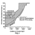
- Figure 1 is a graphical representation of the relationship between cabin altitude and oxygen concentration of breathable gas supplied to the crew of a high performance military aircraft. As discussed above, the oxygen concentration of breathable gas supplied to the aircrew must be within predetermined maximum and minimum limits. The shaded region within Figure 1 represents the permissible levels of oxygen concentration at various cabin altitudes.
- the maximum oxygen concentration is 70% at altitudes up to approximately 5486,42 m (eighteen thousand feet) although a desirable maximum concentration is 60% up to a cabin altitude of 4572 m (fifteen thousand feet) rising linearly with cabin altitude to a value of 70% at 5486,42 m (eighteen thousand feet). From 5486,42 m (eighten thousand feet), the maximum permissible oxygen concentration rises linearly to a value 80% at 6096,02 m (twenty thousand feet). At cabin altitudes above this level, there is no maximum limit for oxygen content in the breathable gas.
- the curve in Figure 1 passing through the shaded region represents the constant oxygen partial pressure at a value corresponding to that of the minimum required in the breathable gas at a cabin altitude of 6096,02 m (twenty thousand feet).
- this curve shows that the gas composition that it represents to have oxygen concentration of 24% as compared with the approximately 20% oxygen content of air at sea level.
- the minimum oxygen content for aircrew breathable gas begins in the lower section as a curve covering cabin altitude ranging from sea level up to approximately 4876,8 m (sixteen thousand feet) where the curve is parallel to the curve representing constant oxygen partial pressure at sea level. Between cabin altitudes of 4876,8 m (sixteen thousand feet) and 6096,02 m (twenty thousand feet), the minimum curve rises linearly and more steeply than the plot of constant oxygen partial pressure to accommodate the effects of accidental rapid cabin depressurization.
- the minimum required oxygen content remains constant at approximately 55%, after which the minimum required content rises with cabin altitude as a continuation of the sea level equivalent partial pressure curve until an altitude of approximately 9448,33 m (thirty-one thousand feet).
- the minimum required oxygen content remains constant at approximately 91% until an altitude of approximately 10972,8 m (thirty-six thousand feet) whereupon the minimum permissible oxygen concentration rises to 98% for all higher altitudes.
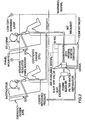
- FIG. 2 a functional schematic diagram is provided of an aircraft on-board oxygen generation system (OBOGS) employing variable bed duty cycle control for regulating oxygen concentration, and a performance check function as discussed in greater detail below.
- OBOGS illustrated in Figure 2 utilizes conditioned engine bleed air and electrical power from the aircraft resources to provide oxygen enriched air for crew member breathing within the range identified as "CONTROL LIMITS" in Figure 1.
- the present invention is embodied within the block labeled "oxygen concentrator with integral monitor/controller.”
- a detailed wiring diagram of the interface between the aircraft and OBOGS of Figure 2 is shown in Figure 4, and is discussed in greater detail below with reference to the performance test features of the present invention.
- the concentrator with integral monitor/controller is shown divided into two functional portions.
- the pressure swing absorption (PSA) portion implements the oxygen concentration function while the controller/monitor (C/M) portion implements control of the PSA components, monitoring of oxygen levels provided to the aircrew and implementing test sequences for all components.
- PSA pressure swing absorption
- C/M controller/monitor
- bleed air enters the concentrator and passes through a filter/water separator FLTR1, through pilot-operated shut-off valve/regulator REG1, which regulates pressure to conserve the air supply at low altitudes when concentrator inlet pressures are greater than required.
- the conditioned air then flows to pilot pressure-driven slide valve V1 which sequentially ports the air to the molecular sieve beds BED1 and BED2.
- the two oxygen beds, BED1 and BED2 operate as an alternating pair so that when one bed is pressurized, adsorbing nitrogen, and producing oxygen-enriched product gas, the other bed is venting to ambient air and desorbing nitrogen from the prior pressurization.
- the regeneration by desorption of nitrogen in the vented bed is enhanced by a reverse flow of oxygen-enriched gas from the output or product end of the pressurized bed.
- the amount of the reverse or purge flow through the vented bed is controlled by purge orifice restrictors ORF1 and ORF2, located in a flow path connected to the output ends of the two beds.
- the two oxygen beds are cycled alternately between the pressurization or oxygen-producing mode and the vented (or flushed), regenerative, nitrogen-purging mode by the slide valve V1.
- the oxygen-enriched output product gas from the pressurized beds flows through check valves CV1 and CV2 and on to the crew member breathing gas delivery lines ( Figure 2).
- Oxygen sensor 02 provides a continuous monitoring of the outlet gas quality and provides a warning signal to detect off-limit conditions, as discussed in greater detail below.
- Filter/water separator FLTR1 functions as a particulate filter as well as a water separator.
- the supply of air passes through the filter FLTR1 such that particles and liquid droplets are trapped.
- Liquid droplets gradually pass through the filter element where they are coalesced at the output surface and removed through a small orifice at the bottom of the filter housing, where a small hose connection attaches a drain line.
- the drain line is routed to the concentrator EXHAUST for disposal of the removed water. Water elimination is therefore automatic and continuous.
- the combination shutoff valve/regulator REG1 is located at the input to the concentrator, just after the filter FLTR1, so that the concentrator may be shut down by a command from the C/M or deactivated when electrical power is removed.
- the shutoff valve utilizes inlet air pressure supplied through the pilot solenoid valve SV4, which is located within the C/M to control the shutoff valve.
- the shutoff valve is spring loaded in the closed position and opens only when pilot solenoid valve SV4 is energized, allowing the inlet pressure to overcome the spring pressure.
- the shutoff valve protects the molecular sieve beds in the event air pressure is available and the C/M does not have electrical power. Screen S3 prevents contaminants from entering solenoid valve SV4.
- the pressure regulator is used to maintain molecular sieve bed pressure, and therefore pressure swing, at a constant value so that unit performance is not affected by upstream variations in air pressure, and to avoid excessive air use when the inlet pressure is high.
- the regulator produces a controlled gauge pressure, and the output pressure is established by a force balance between output pressure against a piston and a helical spring.
- Pressure swing cycling of the molecular sieve beds is accomplished through the use of reciprocating slide valve V1.
- the valve is activated by two opposing air cylinders, CYL1 and CYL2, which are pressurized/vented by two pilot solenoid valves, SV1 and SV2.
- CYL1 and CYL2 When one cylinder is pressurized, the other is vented, and the valve is pushed to one side. This pressurizes one oxygen bed and vents the other.
- An electronic timing circuit in the C/M causes the solenoid valves to change state so that the slide valve moves to the other side, and the other bed is pressurized while the original bed is vented.
- the cycle rate is selected to best accommodate flight conditions.
- Screens S1 and S2 are integral to the slide valve and prevent any particulate matter from entering solenoid valves SV1 and SV2.
- the oxygen beds BED1 and BED2 are preferably constructed of aluminium tubing.
- Check valves CV1 and CV2 are built into the output flow tube of the oxygen beds and direct the output of the producing bed to the connector outlet and limit the backflow which purges the molecular sieve of the nonproducing bed.
- Purge flow for the oxygen beds is accomplished through dual precision-machined orifices ORF1 and ORF2 contained in a crossflow tube connecting the bed caps upstream of the check valves.
- the concentrator includes a C/M that monitors and controls the concentrator.
- the C/M provides the operator with continuous verification of acceptable concentrator performance and detection of concentrator failures, as well as verification of the C/M functionality.
- the oxygen product gas flows through solenoid valve SV3 to oxygen concentrator 02.
- Orifice ORF3 is an integral port of the manifold assembly and limits the flow through the sensor.
- the oxygen sensor chamber pressure is controlled by downstream absolute pressure regulator REG2.
- REG2 downstream absolute pressure regulator
- the small gas sample is then vented out through a vent port in the side of the C/M case.
- Pressure transducer PT1 continuously monitors the cabin pressure and is used in conjunction with the oxygen concentration measurement in calculating the partial pressure of oxygen (PPO 2 ) being supplied to the aircrew.
- PT1 is exposed to cabin ambient conditions and screen S5 protects this port from contaminants.
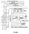
- the C/M provides a warning via a discrete warning signal whenever the partial pressure of oxygen drops below a specified limit, as shown in Figure 6.
- the control function of the C/M includes two solenoid valves, SV1 and SV2, that are alternately energized to control the cycling of the slide valve V1.
- Solenoid valve SV3 is used for the BIT function (discussed in greater detail below). Under normal operation conditions, SV3 is deenergized and continuously routes concentrator product gas to the oxygen sensor. When SV3 is energized, inlet air is supplied to the oxygen sensor to perform an accuracy check on the sensor and associated electronics.
- Solenoid valve SV4 controls the pilot pressure that is supplied to shutoff valve/regulator REG1. When SV4 is energized, inlet pressure is supplied to the shutoff valve and the shutoff valve opens.
- Composition control (which is active for altitudes less than 4572 m (15K ft) is selected by placing the OXYGEN SELECT toggle located on the panel mounted breathing regulator ( Figure 6) in the NORMAL position. This in turn, provides a control signal to the C/M which activates the duty cycle control mechanism. In this mode, the oxygen concentration is controlled within the limits shown in Figure 1. This control is accomplished by varying the operation of the slide valve V1. The slide valve responds to signals from the C/M, which continuously compares the product gas oxygen concentration to an ideal level and varies the slide valve operation accordingly to maintain the required concentration.
- variable bed duty cycle control In normal operation, the two-bed oxygen generating system operates at 50-50% duty cycle (i.e. 3 seconds per bed), as shown in Figure 4a. To control performance of the system, the duty cycles of the two beds are changed so that one bed duty cycle is increased while the other bed duty cycle is decreased, as shown in Figure 4b. The duty cycles can be changed from 50% down to 20% (50% up to 80% on the other bed) at less than 1% steps.
- the bed duty cycles are controlled in alternate pattern. Specifically, one bed dwells in a longer "purge” mode during one control period (e.g. 10 cycles of 6 seconds each), and then reverses to dwell in a longer "generate” mode during the next control period.
- the two beds BED1 and BED2 are able to purge water vapor after their respective dwelling periods and thereby protect the beds from water vapor contamination damage.
- the C/M implements an algorithm or process for duty cycle control beginning at "Control Start”.
- the oxygen concentration is tested via the 02 sensor. If "02> upper limit” is “Yes”, then the C/M functions to "Set Duty cycles closer and Delay”, whereas if"02 ⁇ lower limit” is “No”, then the process returns to "Control Start”. The process also returns to "Control Start” after either of "Set Duty cycles more apart and Delay” or "Set Duty cycles closer and delay”.
- the change in duty cycle depends on how much greater the 02 concentration is than the upper limit or how much smaller the 02 concentration is than the lower limit.
- C/M control/monitor
- M/BIT pressure-swing adsorption subsystem performance check
- SV5 and SV6 are opened to load the concentrator beds BED1 and BED2 at a specific airflow rate.
- the C/M then checks the product oxygen concentration to determine whether the PSA subsystem is performing adequately (i.e. concentration above a predetermined limit (e.g. 50%)).
- the C/M upon application of electrical power (+28 VDC for the C/M and 115 VAC for the aircraft), the C/M automatically executes a Power-Up Built-in-Test (PUB), which is an internal check of C/M integrity and includes a program checksum, a RAM check, and "reasonableness" checks of the oxygen sensor 02 and the cabin pressure transducer PT1. If PUB is successfully completed, the warning remains off and no indication is given via the "OXY LOW" lamp in the aircraft. If any failures are detected, the warning is activated. If PUB fails, momentarily depressing the BIT button on either the forward or aft pilot oxygen regulator front panel repeats PUB.
- PUB Power-Up Built-in-Test
- the C/M After PUB, the C/M enters a warmup state for approximately three minutes. The warning remains OFF during this time. This warmup is required for the oxygen sensor 02 to achieve specified accuracy.
- the C/M performs the sensor accuracy check during the warmup. If the C/M does not receive the air available signal from the aircraft avionics (i.e. "AIR AVAIL" in Figure 6), it will wait indefinitely for the signal. When the signal is received, the C/M automatically performs the sensor accuracy check.
- AIR AVAIL air available signal from the aircraft avionics
- the C/M automatically performs the sensor accuracy test. During this test, concentrator inlet air is supplied to the sensor 02. At the end of 3 minutes, the sensor accuracy is checked by comparing the sensor output to the known value for air. If the accuracy check is successfully completed, the warning remains OFF and no indication is given. If a failure is detected, the warning is activated. If the accuracy test fails, momentarily depressing the BIT button on the regulator front panel repeats the accuracy test.
- the C/M Upon successful completion of the sensor accuracy check, the C/M automatically enter the C-BIT mode of operation. This is the "normal" mode of operation and the C/M continuously compares the calculated oxygen partial pressure (PPO 2 ) of the concentrator product gas with a preset threshold of 24 264,604 N m -2 (182 mmHg) PPO 2 . During C-BIT, the C/M also performs an internal "periodic BIT" that will detect catastrophic failures of the input transducers. Any failures detected result in activation of the warning.
- I-BIT is manually activated by momentarily depressing the BIT button on the regulator front paneL I-BIT verifies that the C/M is capable of activating the warning.
- the C/M energizes solenoid valve SV3 to supply air to the sensor.
- the warning is activated.
- SV3 is then deenergized to switch back to concentrator product gas.
- the warning is deactivated. If, within 2 minutes, the PPO 2 does not fall below 24 264,604 N m -2 (182 mmHg) while exposed to air, or does not return to above 24 264,604 N m -2 (182 mmHg) when again switched to concentrator product gas, the warning is activated. If the I-BIT fails, momentarily depressing the BIT button on the regulator front panel repeats the I-BIT test.
- M-BIT While in C-BIT, the C/M is receptive to an M-BIT command.
- the M-Bit is intended for use by maintenance personnel to perform an extended accuracy test of the C/M oxygen sensor and a performance test of the concentrator. This test requires electrical power and a minimum of 110 316,16 N m -2 (16 psig) is applied to the concentrator.
- the M-Bit is activated by depressing and holding the BIT button on the regulator front panel for 20 seconds. At the end of 20 seconds, the warning is activated to indicate that the C/M is in the M-Bit mode of operation. The BIT button can then be released.
- M-BIT energizes solenoid valve SV3 to supply air to the sensor for a period of 3 minutes. At the end of 3 minutes, the sensor output is compared to a known value for air. If the accuracy test fails, the warning remains on.
- the warning is deactivated and the C/M opens solenoid valves SV5 and SV6 for 2 minutes to establish a known flow from the concentrator.
- the concentrator output is compared to a predetermined minimum limit (e.g. set at 45% oxygen). If the performance test is passed, the warning remains OFF. A failure results in the warning being activated.
- the C/M can open solenoid valves SV5 and SV6 at the start of the command. The point in time at which the warning is activated differentiates between C/M and concentrator failures. If the M-BIT fails, momentarily depressing the BIT button on the regulator front panel returns the C/M to C-BIT mode. M-Bit can be repeated as described above if desired.
Landscapes
- Engineering & Computer Science (AREA)
- Chemical & Material Sciences (AREA)
- Health & Medical Sciences (AREA)
- General Health & Medical Sciences (AREA)
- Pulmonology (AREA)
- Aviation & Aerospace Engineering (AREA)
- Analytical Chemistry (AREA)
- General Chemical & Material Sciences (AREA)
- Oil, Petroleum & Natural Gas (AREA)
- Chemical Kinetics & Catalysis (AREA)
- Separation Of Gases By Adsorption (AREA)
- Respiratory Apparatuses And Protective Means (AREA)
Description
- The present invention relates in general to oxygen generators for aircraft breathing apparatus and a method for controlling its performance, and more particularly to an oxygen concentrator with variable alternating bed duty cycle control to regulate oxygen concentration to within altitude-dependent limits, and a self-test feature to reduce support equipment requirements.
- Oxygen generation for aircraft breathing applications requires that the product gas concentration stays within predetermined altitude-dependent minimum and maximum physiological limits. Normally, the minimum oxygen content of the breathable gas is that required to provide, at all cabin altitudes, the same or greater oxygen partial pressure as at sea level. A maximum oxygen concentration is set to reduce the likelihood of partial lung collapse during low-altitude high G maneuvers. More particularly, the risk of partial lung collapse increases with the risk of total adsorption of entrapped pockets of gas in the lungs, which result from distortion of the lungs during high G maneuvers. The risk of total adsorption of the entrapped gas increases with increased oxygen concentration (i.e. reduced nitrogen concentration).
- Methods are known for the generation of low-pressure oxygen-enriched air. One such method is referred to as pressure swing adsorption (PSA) and has the advantage of being able to provide oxygen-enriched air in a short period of time after the supply of a suitable feed gas (e.g. pressurized air). The pressure swing adsorption process uses pressure to control adsorption and desorption. According to this process, the nitrogen in pressurized air is adsorbed in a molecular sieve bed while the oxygen passes through the bed. When the molecular sieve in the bed has become nearly saturated, the bed is vented to atmospheric pressure. This causes most of the nitrogen-adsorbed gases to be desorbed and discharged from the bed. In a two-bed system, when one bed is producing oxygen, some of the enriched product gas is flushed back through the (vented) other molecular sieve bed to further lower the partial pressure of the adsorbed gases in the vented bed and to complete the desorption process. Using two beds which are pressurized and flushed alternately provides a continuous flow of product gas and ensures sufficient pressure for the flushing operation.
- Aircraft on-board oxygen generation systems (OBOGS) are known in the art. These systems are based on the molecular sieve gas separation process discussed above. Such systems are said to be "self-regulating" since the pressure swing increases with altitude, and therefore the efficiency of the process also increases to ensure sufficient oxygen concentration at high altitudes. More particularly, since each sieve bed is vented to the atmosphere (or cabin) during its regeneration phase, the bed pressure during desorption decreases with increasing altitude, thereby enhancing the desorption process.
- EP-A-0 046 369 discloses a molecular sieve type gas separation system useful for the production of oxygen-enriched air as breathable gas for aircrew. Said system comprises sieve beds which are pressurized and regenerated by operating respective control valves arranged onstream and downstream from said sieve beds. However, a desired concentration of oxygen in the product gas is maintained only by the control of the regeneration period of the respective molecular sieve beds wherein each of the beds is continually operated in a partially saturated condition by restricting the flushing of the bed so as not fully to cleanse the latter at each regeneration (see page 6,
lines 5 to 9). - US 4,693,730 discloses a method and apparatus for automatically controlling product purity in a pressure swing adsorption process. A corrective action to vary the impurity concentration in the product gas includes adjusting the adsorption step time to control the impurity loading of each adsorbent bed.
- EP-A-0 375 220 discloses a pressure swing apparatus including two sorption beds, one of which extracts a component from an inlet gas mixture while the other bed is regenerated. The adsorption and purging intervals of the first and second sorption beds are adjusted to the respective determined intervals that optimize the production of product gas.
- In order to keep the oxygen concentration within maximum limits at low altitudes, processes have been developed to reduce the performance of prior art OBOGS. U.S. Patents 4.661.124 and 5,004,485 (Humphrey, et al), disclose an alternating bed oxygen generating system with controlled sequential operation of charge and vent valves according to a series of selectable overall cycle times ranging between a minimum and a maximum, in a number of discrete steps. By extending the overall cycle time, efficiency of the system is reduced thereby regulating the product gas oxygen gas to within physiological maximum limits.
- In U.S. Patent 4,661,124, the overall cycle time of the molecular sieve beds is controlled using a pressure transducer on the basis of cabin pressure which is indicative of the altitude at which the aircraft is operating.
- In U.S. Patent 5,004,485, an oxygen sensor is used to test the gas concentration and a comparator function is implemented to compare the sensed oxygen concentration with values in a look-up table of desired product gas oxygen concentrations at various altitudes. In response to implementing the comparator function the overall cycle time is controlled to provide suitable concentration levels.
- Prior art systems employing overall cycle time control, such as disclosed in U.S. Patent Nos. 4,661,124 and 5,009,485 (Humphrey et al) suffer from a disadvantage in that it is difficult to accurately control the output oxygen concentration because performance changes occur over a small range (e.g. 4.5 seconds to 5.5 seconds in some systems, whereas cycles ranging from 5.5 seconds to 8.5 seconds do not result in any performance changes).
- Dynamic control of system performance to regulate product gas to within the minimum and maximum physiological limits, requires reliable performance of the oxygen sensor connected to the concentrator output. The use of Built-In-Test (BIT) switches is known in the art for initiating integrity tests for current-limiting oxygen sensors. U.S. Patent 5,071,453 (Hradek, et al) discloses a Built-In-Test function for implementing a system self-test for preflight and an oxygen sensor calibration check for operational level maintenance. When the BIT switch is momentarily depressed, a solenoid valve is energized to direct a flow of air through the oxygen sensor. Once the air reaches the sensor, the sensor output begins to drop indicating reduced oxygen concentration. Upon dropping to below a predetermined warning level, an alarm is activated indicating that the self-test has been successful. If the sensor output does not fall below the predetermined warning level within a defined time period such as 20 seconds, the self- test is deemed to have failed and the warning remains activated. The oxygen sensor calibration check involves energizing the same solenoid valve for passing a flow of air through the sensor in response to a lengthened depression of the BIT switch. During the calibration check, the air flow through the sensor is maintained for a longer period (3 minutes) than during the self-test, so that the sensor output falls below the warning level to within a predetermined threshold calibration range, causing activation of the warning signal. If the output of the oxygen sensor does not fall to within the predetermined calibration range within three minutes, the calibration test is deemed to have failed and the warning remains activated after completion of the test.
- Although systems such as discussed above arc known for testing the operation of oxygen sensors in OBOGS, the lack of maintenance testing systems for oxygen concentrators results in high support equipment requirements including the use of inlet air sources and test sets (to set the concentrator product flow and measure oxygen composition). Inlet air sources can often become contaminated with moisture and oil, and test sets require calibration control.
- In order to resolve the above-mentioned problems, a method of controlling performance of an oxygen concentrator according to the present invention is provided, having a first molecular sieve bed which is operated over successive control periods according to a duty cycle for alternately pressurizing and flushing said first molecular sieve bed and a second molecular sieve bed which is operated over said successive control periods according to a reciprocal of said duty cycle for alternately flushing and pressuring said second molecular sieve bed, the method is characterized by the steps of a) said successive control periods each comprising a plurality of duty cycles which include time periods, adjusting time periods during successive duty cycles and time periods during the corresponding reciprocal duty cycles during every second one of said successive control periods to prolong the time period for pressurizing relative to the time period for flushing of said first molecular sieve bed and to prolong the time period for flushing relative to the time period for pressurizing of said second molecular sieve bed, thereby degrading performance of said oxygen concentrator for reducing concentration of oxygen produced by said first molecular sieve bed and purging water from said second molecular sieve bed, and b) adjusting time periods during successive duty cycles and time periods during the corresponding reciprocal duty cycles during remaining control periods to prolong the time period for flushing relative to the time period for pressurizing of said first molecular sieve bed and to prolong the time period for pressurizing relative to the time period for flushing of said second molecular sieve bed, thereby purging water from said first molecular sieve bed and degrading performance of said oxygen concentrator for reducing concentration of oxygen produced by said second molecular sieve bed.
- Further, an aircraft oxygen system for providing a controlled concentration of oxygen to the cabin of said aircraft comprises an air inlet, an exhaust port, slide valve connected to said air inlet and said exhaust port, first and second molecular sieve beds each having an inlet connected to said slide valve and an outlet to said cabin, wherein said first and second molecular sieve beds are operated during successive control periods, characterized in that a controller operates said slide valve over successive control periods, said control periods each comprising a plurality of duty cycles which include time periods, at high altitudes according to a duty cycle for alternately pressurizing and flushing said first molecular sieve bed and a reciprocal of said duty cycle for alternately flushing and pressurizing said second molecular sieve bed to generate oxygen enriched gas, wherein said controller controlling said slide valve for adjusting said duty cycle and said reciprocal duty cycle during every second one of said successive control periods to prolong the time period for pressurizing relative to the time period for flushing of said first molecular sieve bed and to prolong the time period for flushing relative to the time period for pressurizing of said second molecular sieve bed, thereby reducing the concentration of oxygen in said product gas produced from said first molecular sieve bed and purging water vapor from said second molecular sieve bed, and wherein said controller controlling said slide valve for adjusting said duty cycle and said reciprocal duty cycle during remaining control periods to prolong the time period for flushing relative to the time period for pressurizing of said first molecular sieve bed and to prolong the time period for pressurizing relative to the time period for flushing of said second molecular sieve bed, thereby purging water vapor from said first molecular sieve bed and reducing the concentration of oxygen in said product gas produced from said second molecular sieve bed.
- According to the present invention, said on-board oxygen generation system (OBOGS) is provided employing variable bed duty cycle control for regulating the oxygen concentrator output from as low as 30% oxygen concentration to higher than 90% concentration. The variable bed duty cycle control is flexible and accurately controllable. The variable bed duty cycle control of the present invention provides more stable operation than prior art OBOGS with overall cycle length control, such as disclosed in U.S. Patents 4,661,124 and 5,004,485 (Humphries, et al.).
- During normal operation, the two-bed oxygen generating system of the present invention operates at a 50%-50% duty cycle (e.g. 3 seconds per bed for a 6 second cycle). To control performance of the system, the duty cycles of the two beds are adjusted so that one bed duty cycle is increased while the other bed duty cycle is decreased. The duty cycles can be changed from 50% down to 20% (and from 50% up to 80% on the other bed), at less than 1% steps for enhanced accuracy.
- In order to protect the beds from damage due to water vapor contamination, the beds' duty cycles are controlled in an alternating pattern. That is to say, one bed dwells at a longer duty cycle for one control period (e.g. 10 cycles) than the other bed, and vice versa on the next control cycle. By alternating the beds' duty cycles, the two beds are able to purge water vapor after their respective dwelling period.
- A further aspect of the present invention is the provision of a pressure-swing adsorption (PSA) subsystem performance check. This test is performed as part of a maintenance BIT (Built-In-Test) function. After verifying that the oxygen sensor accuracy is acceptable using prior art techniques, a set of bleed valves are opened to load the oxygen concentrator at a specific flow. The oxygen concentration is then checked via the sensor to determine whether the PSA subsystem is operating to within specification (i.e. concentration limit above a predetermined level - such as 50%).
- A detailed description of the preferred embodiment is provided herein below, with reference to the following drawings in which:
- Figure 1 shows oxygen concentration curves which govern the operation of the oxygen generator according to the preferred embodiment;
- Figure 2 is a functional schematic of an aircraft on-board oxygen generation system (OBOGS) incorporating a PSA concentrator subsystem and controller/monitor according to the preferred embodiment;
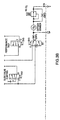
- Figure 3 is a pneumatic schematic of the PSA concentrator subsystem and controller/monitor according to the preferred embodiment;
- Figure 4 comprises Figures 4a and 4b, and is a timing diagram showing the alternating beds' duty cycle control of the PSA concentrator subsystem according to the preferred embodiment;
- Figure 5 is a flowchart showing an algorithm implemented by the controller/monitor for the duty cycle control shown in Figure 4; and
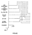
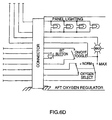
- Figure 6 is a wiring diagram of the OBOGS shown in Figure 2, according to the preferred embodiment.
-
- Figure 1 is a graphical representation of the relationship between cabin altitude and oxygen concentration of breathable gas supplied to the crew of a high performance military aircraft. As discussed above, the oxygen concentration of breathable gas supplied to the aircrew must be within predetermined maximum and minimum limits. The shaded region within Figure 1 represents the permissible levels of oxygen concentration at various cabin altitudes.
- The maximum oxygen concentration is 70% at altitudes up to approximately 5486,42 m (eighteen thousand feet) although a desirable maximum concentration is 60% up to a cabin altitude of 4572 m (fifteen thousand feet) rising linearly with cabin altitude to a value of 70% at 5486,42 m (eighteen thousand feet). From 5486,42 m (eighten thousand feet), the maximum permissible oxygen concentration rises linearly to a
value 80% at 6096,02 m (twenty thousand feet). At cabin altitudes above this level, there is no maximum limit for oxygen content in the breathable gas. - The curve in Figure 1 passing through the shaded region (except for a portion in the vicinity of twenty thousand feet identified as "24 264,604 Nm-2 (182 mmHg)-warning below this level"), represents the constant oxygen partial pressure at a value corresponding to that of the minimum required in the breathable gas at a cabin altitude of 6096,02 m (twenty thousand feet). At sea level, this curve shows that the gas composition that it represents to have oxygen concentration of 24% as compared with the approximately 20% oxygen content of air at sea level.
- The minimum oxygen content for aircrew breathable gas begins in the lower section as a curve covering cabin altitude ranging from sea level up to approximately 4876,8 m (sixteen thousand feet) where the curve is parallel to the curve representing constant oxygen partial pressure at sea level. Between cabin altitudes of 4876,8 m (sixteen thousand feet) and 6096,02 m (twenty thousand feet), the minimum curve rises linearly and more steeply than the plot of constant oxygen partial pressure to accommodate the effects of accidental rapid cabin depressurization. Between 6096,02 m (twenty thousand feet) and 7010,4 m (twenty-three thousand feet), the minimum required oxygen content remains constant at approximately 55%, after which the minimum required content rises with cabin altitude as a continuation of the sea level equivalent partial pressure curve until an altitude of approximately 9448,33 m (thirty-one thousand feet). At 9448,33 m (thirty-one thousand feet) the minimum required oxygen content remains constant at approximately 91% until an altitude of approximately 10972,8 m (thirty-six thousand feet) whereupon the minimum permissible oxygen concentration rises to 98% for all higher altitudes.
- With reference to Figure 2, a functional schematic diagram is provided of an aircraft on-board oxygen generation system (OBOGS) employing variable bed duty cycle control for regulating oxygen concentration, and a performance check function as discussed in greater detail below. The OBOGS illustrated in Figure 2 utilizes conditioned engine bleed air and electrical power from the aircraft resources to provide oxygen enriched air for crew member breathing within the range identified as "CONTROL LIMITS" in Figure 1. The present invention is embodied within the block labeled "oxygen concentrator with integral monitor/controller." A detailed wiring diagram of the interface between the aircraft and OBOGS of Figure 2 is shown in Figure 4, and is discussed in greater detail below with reference to the performance test features of the present invention.
- Turning to the concentrator pneumatic schematic of Figure 3, the concentrator with integral monitor/controller is shown divided into two functional portions. The pressure swing absorption (PSA) portion implements the oxygen concentration function while the controller/monitor (C/M) portion implements control of the PSA components, monitoring of oxygen levels provided to the aircrew and implementing test sequences for all components.
- In operation, bleed air enters the concentrator and passes through a filter/water separator FLTR1, through pilot-operated shut-off valve/regulator REG1, which regulates pressure to conserve the air supply at low altitudes when concentrator inlet pressures are greater than required. The conditioned air then flows to pilot pressure-driven slide valve V1 which sequentially ports the air to the molecular sieve beds BED1 and BED2.
- The two oxygen beds, BED1 and BED2, operate as an alternating pair so that when one bed is pressurized, adsorbing nitrogen, and producing oxygen-enriched product gas, the other bed is venting to ambient air and desorbing nitrogen from the prior pressurization. The regeneration by desorption of nitrogen in the vented bed is enhanced by a reverse flow of oxygen-enriched gas from the output or product end of the pressurized bed. The amount of the reverse or purge flow through the vented bed is controlled by purge orifice restrictors ORF1 and ORF2, located in a flow path connected to the output ends of the two beds.
- The two oxygen beds are cycled alternately between the pressurization or oxygen-producing mode and the vented (or flushed), regenerative, nitrogen-purging mode by the slide valve V1. The oxygen-enriched output product gas from the pressurized beds flows through check valves CV1 and CV2 and on to the crew member breathing gas delivery lines (Figure 2).
Oxygen sensor 02 provides a continuous monitoring of the outlet gas quality and provides a warning signal to detect off-limit conditions, as discussed in greater detail below. - Filter/water separator FLTR1 functions as a particulate filter as well as a water separator. The supply of air passes through the filter FLTR1 such that particles and liquid droplets are trapped. Liquid droplets gradually pass through the filter element where they are coalesced at the output surface and removed through a small orifice at the bottom of the filter housing, where a small hose connection attaches a drain line. The drain line is routed to the concentrator EXHAUST for disposal of the removed water. Water elimination is therefore automatic and continuous.
- The combination shutoff valve/regulator REG1 is located at the input to the concentrator, just after the filter FLTR1, so that the concentrator may be shut down by a command from the C/M or deactivated when electrical power is removed. The shutoff valve utilizes inlet air pressure supplied through the pilot solenoid valve SV4, which is located within the C/M to control the shutoff valve. The shutoff valve is spring loaded in the closed position and opens only when pilot solenoid valve SV4 is energized, allowing the inlet pressure to overcome the spring pressure. The shutoff valve protects the molecular sieve beds in the event air pressure is available and the C/M does not have electrical power. Screen S3 prevents contaminants from entering solenoid valve SV4.
- The pressure regulator is used to maintain molecular sieve bed pressure, and therefore pressure swing, at a constant value so that unit performance is not affected by upstream variations in air pressure, and to avoid excessive air use when the inlet pressure is high.
- The regulator produces a controlled gauge pressure, and the output pressure is established by a force balance between output pressure against a piston and a helical spring.
- Pressure swing cycling of the molecular sieve beds is accomplished through the use of reciprocating slide valve V1. The valve is activated by two opposing air cylinders, CYL1 and CYL2, which are pressurized/vented by two pilot solenoid valves, SV1 and SV2. When one cylinder is pressurized, the other is vented, and the valve is pushed to one side. This pressurizes one oxygen bed and vents the other. An electronic timing circuit in the C/M causes the solenoid valves to change state so that the slide valve moves to the other side, and the other bed is pressurized while the original bed is vented. The cycle rate is selected to best accommodate flight conditions.
- Screens S1 and S2 are integral to the slide valve and prevent any particulate matter from entering solenoid valves SV1 and SV2.
- The oxygen beds BED1 and BED2 are preferably constructed of aluminium tubing.
- Check valves CV1 and CV2 are built into the output flow tube of the oxygen beds and direct the output of the producing bed to the connector outlet and limit the backflow which purges the molecular sieve of the nonproducing bed.
- Purge flow for the oxygen beds is accomplished through dual precision-machined orifices ORF1 and ORF2 contained in a crossflow tube connecting the bed caps upstream of the check valves.
- As shown in Figures 2 and 6, the concentrator includes a C/M that monitors and controls the concentrator. The C/M provides the operator with continuous verification of acceptable concentrator performance and detection of concentrator failures, as well as verification of the C/M functionality.
- In the normal monitoring mode, the oxygen product gas flows through solenoid valve SV3 to
oxygen concentrator 02. Orifice ORF3 is an integral port of the manifold assembly and limits the flow through the sensor. The oxygen sensor chamber pressure is controlled by downstream absolute pressure regulator REG2. The small gas sample is then vented out through a vent port in the side of the C/M case. Pressure transducer PT1 continuously monitors the cabin pressure and is used in conjunction with the oxygen concentration measurement in calculating the partial pressure of oxygen (PPO2) being supplied to the aircrew. PT1 is exposed to cabin ambient conditions and screen S5 protects this port from contaminants. - The C/M provides a warning via a discrete warning signal whenever the partial pressure of oxygen drops below a specified limit, as shown in Figure 6.
- The control function of the C/M includes two solenoid valves, SV1 and SV2, that are alternately energized to control the cycling of the slide valve V1.
- Solenoid valve SV3 is used for the BIT function (discussed in greater detail below). Under normal operation conditions, SV3 is deenergized and continuously routes concentrator product gas to the oxygen sensor. When SV3 is energized, inlet air is supplied to the oxygen sensor to perform an accuracy check on the sensor and associated electronics.
- Solenoid valve SV4 controls the pilot pressure that is supplied to shutoff valve/regulator REG1. When SV4 is energized, inlet pressure is supplied to the shutoff valve and the shutoff valve opens.
- Composition control (which is active for altitudes less than 4572 m (15K ft) is selected by placing the OXYGEN SELECT toggle located on the panel mounted breathing regulator (Figure 6) in the NORMAL position. This in turn, provides a control signal to the C/M which activates the duty cycle control mechanism. In this mode, the oxygen concentration is controlled within the limits shown in Figure 1. This control is accomplished by varying the operation of the slide valve V1. The slide valve responds to signals from the C/M, which continuously compares the product gas oxygen concentration to an ideal level and varies the slide valve operation accordingly to maintain the required concentration.
- More particularly, as discussed above, in order to keep the product gas concentration within limits at lower altitudes, a process is developed in accordance with the present invention to degrade the performance of the oxygen concentrator system. This process is termed variable bed duty cycle control. In normal operation, the two-bed oxygen generating system operates at 50-50% duty cycle (i.e. 3 seconds per bed), as shown in Figure 4a. To control performance of the system, the duty cycles of the two beds are changed so that one bed duty cycle is increased while the other bed duty cycle is decreased, as shown in Figure 4b. The duty cycles can be changed from 50% down to 20% (50% up to 80% on the other bed) at less than 1% steps.
- As shown in Figure 4b, in order to protect the beds from damage by water vapor contamination, the bed duty cycles are controlled in alternate pattern. Specifically, one bed dwells in a longer "purge" mode during one control period (e.g. 10 cycles of 6 seconds each), and then reverses to dwell in a longer "generate" mode during the next control period. By alternating the variable bed duty cycle, the two beds (BED1 and BED2) are able to purge water vapor after their respective dwelling periods and thereby protect the beds from water vapor contamination damage.
- As shown in Figure 5, the C/M implements an algorithm or process for duty cycle control beginning at "Control Start". First, the oxygen concentration is tested via the 02 sensor. If "02> upper limit" is "Yes", then the C/M functions to "Set Duty cycles closer and Delay", whereas if"02< lower limit" is "No", then the process returns to "Control Start". The process also returns to "Control Start" after either of "Set Duty cycles more apart and Delay" or "Set Duty cycles closer and delay". Thus, the change in duty cycle depends on how much greater the 02 concentration is than the upper limit or how much smaller the 02 concentration is than the lower limit.
- As discussed above, according to another aspect of the present invention, self test features are designed into the control/monitor (C/M) in order to reduce support equipment requirements. The various modes of operation of the C/M are discussed in detail below. One of the unique features is the pressure-swing adsorption (PSA) subsystem performance check (maintenance BIT (M/BIT)). After verifying that the oxygen sensor accuracy is acceptable, a set of bleed valves (SV5 and SV6) are opened to load the concentrator beds BED1 and BED2 at a specific airflow rate. The C/M then checks the product oxygen concentration to determine whether the PSA subsystem is performing adequately (i.e. concentration above a predetermined limit (e.g. 50%)).
- Turning now to Figure 6, upon application of electrical power (+28 VDC for the C/M and 115 VAC for the aircraft), the C/M automatically executes a Power-Up Built-in-Test (PUB), which is an internal check of C/M integrity and includes a program checksum, a RAM check, and "reasonableness" checks of the
oxygen sensor 02 and the cabin pressure transducer PT1. If PUB is successfully completed, the warning remains off and no indication is given via the "OXY LOW" lamp in the aircraft. If any failures are detected, the warning is activated. If PUB fails, momentarily depressing the BIT button on either the forward or aft pilot oxygen regulator front panel repeats PUB. - After PUB, the C/M enters a warmup state for approximately three minutes. The warning remains OFF during this time. This warmup is required for the
oxygen sensor 02 to achieve specified accuracy. - If air is present, the C/M performs the sensor accuracy check during the warmup. If the C/M does not receive the air available signal from the aircraft avionics (i.e. "AIR AVAIL" in Figure 6), it will wait indefinitely for the signal. When the signal is received, the C/M automatically performs the sensor accuracy check.
- Once the C/M receives the air available signal from the aircraft, the C/M automatically performs the sensor accuracy test. During this test, concentrator inlet air is supplied to the
sensor 02. At the end of 3 minutes, the sensor accuracy is checked by comparing the sensor output to the known value for air. If the accuracy check is successfully completed, the warning remains OFF and no indication is given. If a failure is detected, the warning is activated. If the accuracy test fails, momentarily depressing the BIT button on the regulator front panel repeats the accuracy test. - Upon successful completion of the sensor accuracy check, the C/M automatically enter the C-BIT mode of operation. This is the "normal" mode of operation and the C/M continuously compares the calculated oxygen partial pressure (PPO2) of the concentrator product gas with a preset threshold of 24 264,604 N m-2 (182 mmHg) PPO2. During C-BIT, the C/M also performs an internal "periodic BIT" that will detect catastrophic failures of the input transducers. Any failures detected result in activation of the warning.
- While in the C-BIT mode, the C/M is receptive to an I-BIT command. I-BIT is manually activated by momentarily depressing the BIT button on the regulator front paneL I-BIT verifies that the C/M is capable of activating the warning. When the BIT button is momentarily depressed, the C/M energizes solenoid valve SV3 to supply air to the sensor. When the air reaches the sensor and the PPO2 level drops below the 24 264,604 N m-2 (182 mmHg) threshold, the warning is activated. SV3 is then deenergized to switch back to concentrator product gas. When the PPO2 level returns to above the 24 264,604 N m-2 (182mmHg) threshold, the warning is deactivated. If, within 2 minutes, the PPO2 does not fall below 24 264,604 N m-2 (182 mmHg) while exposed to air, or does not return to above 24 264,604 N m-2 (182 mmHg) when again switched to concentrator product gas, the warning is activated. If the I-BIT fails, momentarily depressing the BIT button on the regulator front panel repeats the I-BIT test.
- While in C-BIT, the C/M is receptive to an M-BIT command. The M-Bit is intended for use by maintenance personnel to perform an extended accuracy test of the C/M oxygen sensor and a performance test of the concentrator. This test requires electrical power and a minimum of 110 316,16 N m-2 (16 psig) is applied to the concentrator. The M-Bit is activated by depressing and holding the BIT button on the regulator front panel for 20 seconds. At the end of 20 seconds, the warning is activated to indicate that the C/M is in the M-Bit mode of operation. The BIT button can then be released. M-BIT energizes solenoid valve SV3 to supply air to the sensor for a period of 3 minutes. At the end of 3 minutes, the sensor output is compared to a known value for air. If the accuracy test fails, the warning remains on.
- If the sensor accuracy is within limits, the warning is deactivated and the C/M opens solenoid valves SV5 and SV6 for 2 minutes to establish a known flow from the concentrator. At the end of 2 minutes, the concentrator output is compared to a predetermined minimum limit (e.g. set at 45% oxygen). If the performance test is passed, the warning remains OFF. A failure results in the warning being activated. Alternatively, the C/M can open solenoid valves SV5 and SV6 at the start of the command. The point in time at which the warning is activated differentiates between C/M and concentrator failures. If the M-BIT fails, momentarily depressing the BIT button on the regulator front panel returns the C/M to C-BIT mode. M-Bit can be repeated as described above if desired.
- A summary of the warning signal operation and applicable operator action is set forth in Table 1.
Operational Modes "Warning Signal" Summary MODE Warning Signal Operator Actions (Comments) 1) Power-up-BIT (in Progress) OFF (1 to 2-second electronics test, automatic on application of power) Power-Up BIT (Pass) OFF (Automatically proceed to warmup) Power-Up BIT (Fail) ON (latch) Press BIT button to repeat PUB 2) Warmup (In Progress) OFF (3-minute sensor warm-up; continuously checks for inlet air signal; will bypass "wait" if air is available) 3) Wait (Inlet Air Available) OFF (Automatically proceed to sensor accuracy test) Wait (Inlet Air Not Available) ON (activate) None (ON after the 3-minute warmup; will wait indefinitely for inlet air signal; pressing the BIT button will have no effect) 4) Sensor Accuracy Test (In Progress) OFF (3-minute test from the time air is available, may be combined with warmup) Sensor Accuracy Test (Pass) OFF (Automatically proceed to C-BIT) Sensor Accuracy Test (Fail) ON (latch) Press BIT button to repeat sensor accuracy test 5) Continuous BIT (In Progress) OFF May run I-BIT or M-BIT. (PP02 monitoring only) Continuous BIT (Fail) ON (active) None (Continuous monitoring; warning will go OFF if PP02 goes above threshold; pressing the BIT button will run I-BIT) 6) I-BIT (In Progress/Pass) OFF/ON/OFF (May take up to 2 minutes) I-BIT (In Progress/Fail) OFF/ON latch Press BIT button to repeat I-BIT (ON after 2-minute timeout) 7) M-BIT (In Progress/Pass) ON/OFF (Automatically returns to C-BIT) M-BIT (In Progress/Fail; Accuracy test) ON (latch) Press BIT Button to return to C-BIT M-BIT (In Progress/Fail; Concentrator test) ON/OFF/ON (latch) Press BIT Button to return to C-BIT
Claims (12)
- A method of controlling performance of an oxygen concentrator having a first molecular sieve bed (BED1) which is operated over successive control periods according to a duty cycle for alternately pressurizing and flushing said first molecular sieve bed (BED1) and a second molecular sieve bed (BED2) which is operated over said successive control periods according to a reciprocal of said duty cycle for alternately flushing and pressuring said second molecular sieve bed (BED2), the method
characterized by
said successive control periods each comprising a plurality of duty cycles which include time periods,
and further by the steps of:a) adjusting time periods during successive duty cycles and time periods during the corresponding reciprocal duty cycles during every second one of said successive control periods to prolong the time period for pressurizing relative to the time period for flushing of said first molecular sieve bed (BED1) and to prolong the time period for flushing relative to the time period for pressurizing of said second molecular sieve bed (BED2), thereby degrading performance of said oxygen concentrator for reducing concentration of oxygen produced by said first molecular sieve bed (BED1) and purging water from said second molecular sieve bed (BED2), andb) adjusting time periods during successive duty cycles and time periods during the corresponding reciprocal duty cycles during remaining control periods to prolong the time period for flushing relative to the time period for pressurizing of said first molecular sieve bed (BED1) and to prolong the time period for pressurizing relative to the time period for flushing of said second molecular sieve bed (BED2). thereby purging water from said first molecular sieve bed (BED 1) and degrading performance of said oxygen concentrator for reducing concentration of oxygen produced by said second molecular sieve bed (BED2). - The method of claim 1, wherein said duty cycle of pressurizing and flushing is adjusted within a range of from 50 %-50 % for highest performance to 80 %-20 % for lowest performance.
- The method of claim 1 or 2, wherein each of the time periods of a duty cycle during a control period is the same.
- The method of claim 1 or 2, wherein the time period for pressurizing a respective one of said first and second molecular sieve beds (BED1; BED2) is shortened when the oxygen concentration reaches a predetermined minimum level.
- The method of claim 1 or 2, wherein the time period for pressurizing a respective one of said first and second molecular sieve beds (BED1; BED2) is lengthened when the oxygen concentration reaches a predetermined maximum level.
- An aircraft oxygen system for providing a controlled concentration of oxygen to the cabin of said aircraft, comprising:said controller controlling said slide valve (VI) for adjusting said duty cycle and said reciprocal duty cycle during every second one of said successive control periods to prolong the time period for pressurizing relative to the time period for flushing of said first molecular sieve bed (BED1) and to prolong the time period for flushing relative to the time period for pressurizing of said second molecular sieve bed (BED2), thereby reducing the concentration of oxygen in said product gas produced from said first molecular sieve bed (BED 1) and purging water vapor from said second molecular sieve bed (BED2); and whereinan air inlet;an exhaust port:slide valve (V1) connected to said air inlet and said exhaust port;first and second molecular sieve beds (BED 1; BED2) each having an inlet connected to said slide valve (V1) and an outlet to said cabin, wherein said first and second molecular sieve beds (BED 1; BED 2) are operated during successive control periods, characterized in thata controller operates said slide valve (V1) over successive control periods, said control periods each comprising a plurality of duty cycles which include time periods, at high altitudes according to a duty cycle for alternately pressurizing and flushing said first molecular sieve bed (BED1) and a reciprocal of said duty cycle for alternately flushing and pressurizing said second molecular sieve bed (BED2) to generate oxygen enriched gas, wherein
said controller controlling said slide valve (V1) for adjusting said duty cycle and said reciprocal duty cycle during remaining control periods to prolong the time period for flushing relative to the time period for pressurizing of said first molecular sieve bed (BED 1) and to prolong the time period for pressurizing relative to the time period for flushing of said second molecular sieve bed (BED2), thereby purging water vapor from said first molecular sieve bed (BED1) and reducing the concentration of oxygen in said product gas produced from said second molecular sieve bed (BED2). - The aircraft oxygen system of claim 6, further comprising an oxygen sensor (02) for measuring oxygen concentration of said product gas produced by said first and second molecular sieve beds (BED1; BED2) and communicating said oxygen concentration to said controller for controlling said duty cycle and said reciprocal duty cycle.
- The aircraft oxygen system of claim 6, further comprising a built-in-test system for applying ambient air to said oxygen sensor (02) for a first predetermined time period, comparing the oxygen concentration in the ambient air detected by said sensor to a predetermined threshold value and in the event said oxygen concentration is not below said predetermined threshold value then activating an alarm to indicate malfunction of said sensor.
- The aircraft oxygen system of claims 8, further comprising an oxygen concentrator performance check system for applying a predetermined flow of said product gas from said first and second molecular sieve beds (BED1; BED2) for a further predetermined time period, comparing the oxygen concentration of said product gas at said outlet detected by said sensor to a further predetermined threshold value and in the event said oxygen concentration is not above said further predetermined threshold value then activating an alarm to indicate malfunction of said molecular sieve beds (BED1; BED2).
- The aircraft oxygen system of claim 6, wherein said slide valve (V1) is connected to a pair of opposing air cylinders (CYL1; CYL2) which are alternately pressurized and vented by a pair of pilot operated solenoid valves (SV1: SV2) connected to said controller, such that when a first one (CYL1) of said cylinders is pressurized the other one (CYL2) of said cylinders is vented and said slide valve (V1) is pushed in a first direction for pressurizing said first molecular sieve bed (BED1) and flushing said second molecular sieve bed (BED2) and when the other one (CYL2) of said cylinders is pressurized the first one (CYL1) of said cylinders is vented and said slide valve (V1) is pushed in an opposite direction for pressurizing said second molecular sieve bed (BED2) and flushing said first molecular sieve bed (BED1).
- The system of any one of claims 6 to 10, wherein the time period for pressurizing a respective one of said first and second molecular sieve beds is shortened when the oxygen concentration of the product gas reaches a predetermined minimum level.
- The system of any one of claims 6 to 10, wherein the time period for pressurizing a respective one of said first and second molecular sieve beds is lengthened when the oxygen concentration of the product gas reaches a predetermined maximum level.
Applications Claiming Priority (2)
| Application Number | Priority Date | Filing Date | Title |
|---|---|---|---|
| US08/868,419 US5858063A (en) | 1997-06-03 | 1997-06-03 | Oxygen concentrator with beds' duty cycle control and self-test |
| US868419 | 1997-06-03 |
Publications (3)
| Publication Number | Publication Date |
|---|---|
| EP0882484A2 EP0882484A2 (en) | 1998-12-09 |
| EP0882484A3 EP0882484A3 (en) | 1999-03-10 |
| EP0882484B1 true EP0882484B1 (en) | 2003-07-02 |
Family
ID=25351651
Family Applications (1)
| Application Number | Title | Priority Date | Filing Date |
|---|---|---|---|
| EP98107180A Expired - Lifetime EP0882484B1 (en) | 1997-06-03 | 1998-04-20 | Oxygen concentrator with adsorption beds' duty cycle control and self-test |
Country Status (6)
| Country | Link |
|---|---|
| US (1) | US5858063A (en) |
| EP (1) | EP0882484B1 (en) |
| JP (1) | JP4486170B2 (en) |
| KR (1) | KR100533179B1 (en) |
| CA (1) | CA2234759C (en) |
| DE (1) | DE69815950T2 (en) |
Cited By (1)
| Publication number | Priority date | Publication date | Assignee | Title |
|---|---|---|---|---|
| CN103520848A (en) * | 2012-06-28 | 2014-01-22 | 联合技术公司 | Emergency oxygen supply mask and emergency oxygen supply arrangement adapted for rescuing a passenger of an aircraft in an emergency situation, method of rescuing a passenger of an aircraft in an emergency situation |
Families Citing this family (59)
| Publication number | Priority date | Publication date | Assignee | Title |
|---|---|---|---|---|
| US5858063A (en) * | 1997-06-03 | 1999-01-12 | Litton Systems, Inc. | Oxygen concentrator with beds' duty cycle control and self-test |
| FR2772637B1 (en) * | 1997-12-18 | 2000-02-11 | Air Liquide | GAS SEPARATION PROCESS BY ADSORPTION WITH VARIABLE FLOW PRODUCTION, ESPECIALLY FOR OXYGEN PRODUCTION |
| FR2785554B1 (en) * | 1998-11-09 | 2000-12-22 | Air Liquide | PSA OR VSA UNIT WITH JOINTLY REGULATED FLOW RATE AND PRESSURE |
| US6368491B1 (en) * | 2000-11-08 | 2002-04-09 | Northrop Grumman Corporation | Method of controlling a modular ceramic oxygen generating system |
| US6511526B2 (en) * | 2001-01-12 | 2003-01-28 | Vbox, Incorporated | Pressure swing adsorption gas separation method and apparatus |
| GB0123310D0 (en) * | 2001-09-28 | 2001-11-21 | Honeywell Normalair Garrett | Breathing gas supply system |
| GB0204886D0 (en) * | 2002-03-01 | 2002-04-17 | Honeywell Normalair Garrett | Breathing gas supply system |
| KR100491684B1 (en) * | 2002-04-12 | 2005-05-30 | 주식회사 옥서스 | Gas concentrating Method and apparatus for use of Pressure Swing Adsorption |
| FR2839263B1 (en) * | 2002-05-03 | 2005-01-14 | Air Liquide | OXYGEN PRODUCTION SYSTEM FOR AIRCRAFT, IN PARTICULAR AIRCRAFT WITH A LONG RAY OF ACTION |
| US6997970B2 (en) * | 2002-06-25 | 2006-02-14 | Carleton Life Support Systems, Inc. | Oxygen/inert gas generator |
| US6669758B1 (en) | 2002-06-27 | 2003-12-30 | Carleton Life Support Systems, Inc. | Variable inlet air restriction for composition control of product gas |
| US6712876B2 (en) * | 2002-08-27 | 2004-03-30 | Litton Systems, Inc. | Oxygen concentrator system with altitude compensation |
| US6712877B2 (en) * | 2002-08-27 | 2004-03-30 | Litton Systems, Inc. | Oxygen concentrator system |
| GB0230098D0 (en) * | 2002-12-24 | 2003-01-29 | Honeywell Normalair Garrett | Method of controlling a gas absorption apparatus |
| GB0303936D0 (en) * | 2003-02-21 | 2003-03-26 | Honeywell Normalair Garrett | Method of testing |
| US7036521B2 (en) * | 2003-04-27 | 2006-05-02 | Carleton Life Support Systems, Inc. | Air conserving slide valve |
| US20040211414A1 (en) * | 2003-04-28 | 2004-10-28 | Litton Systems, Inc. | Oxygen concentration system having selectable beds |
| DE10323137B4 (en) * | 2003-05-22 | 2008-04-30 | DRäGER AEROSPACE GMBH | Apparatus for enriching air with oxygen in an aircraft and a method for operating the apparatus |
| US6953928B2 (en) * | 2003-10-31 | 2005-10-11 | Applera Corporation | Ion source and methods for MALDI mass spectrometry |
| FR2880328B1 (en) * | 2005-01-06 | 2008-08-22 | L'air Liquide | METHOD AND SYSTEM FOR VERIFYING THE CORRECT OPERATION OF AN ONBOARD OXYGEN PRODUCTION EQUIPMENT FOR AN AIRCRAFT |
| FR2882662B1 (en) * | 2005-03-03 | 2007-04-27 | Air Liquide | SYSTEM AND METHOD FOR FILTRATION OF A COMPRESSED AIRCRAFT AIR FLOW PROVIDED WITH SUCH A FILTRATION SYSTEM |
| US20060260711A1 (en) * | 2005-04-22 | 2006-11-23 | Audubon Machinery Corporation | Oxygen filling apparatus |
| US7445660B2 (en) * | 2005-04-27 | 2008-11-04 | Carleton Life Support Systems, Inc. | Method for operating gas generators in tandem |
| US7708802B1 (en) | 2005-05-23 | 2010-05-04 | Inogen, Inc. | Gas fractionalization apparatus with built-in administrative and self-diagnostic functions |
| US20080154481A1 (en) * | 2006-12-21 | 2008-06-26 | Stroia Bradlee J | Adaptive oxygen sensor methods, systems, and software |
| US7803218B2 (en) * | 2007-02-26 | 2010-09-28 | Honeywell International Inc. | Drain valve assembly |
| US20090065007A1 (en) * | 2007-09-06 | 2009-03-12 | Wilkinson William R | Oxygen concentrator apparatus and method |
| USD606655S1 (en) | 2008-06-27 | 2009-12-22 | Inova Labs, Llc | Portable oxygen concentrator |
| US8171932B2 (en) * | 2008-07-11 | 2012-05-08 | Intertechnique, S.A. | Oxygen breathing device for an aircraft |
| EP2143636B1 (en) * | 2008-07-11 | 2012-04-11 | Intertechnique | Oxygen breathing device for an aircraft |
| US20120055475A1 (en) | 2010-09-07 | 2012-03-08 | Wilkinson William R | Oxygen concentrator system and methods for oral delivery of oxygen enriched gas |
| US8616207B2 (en) | 2010-09-07 | 2013-12-31 | Inova Labs, Inc. | Oxygen concentrator heat management system and method |
| US8694181B2 (en) * | 2012-03-12 | 2014-04-08 | Honeywell International Inc. | Cabin pressure control system with multiple outflow valves and method of calibrating the outflow valve position feedback during flight |
| AU2013328915B2 (en) | 2012-10-12 | 2018-04-26 | Inova Labs, Inc. | Dual oxygen concentrator systems and methods |
| US9440036B2 (en) | 2012-10-12 | 2016-09-13 | InovaLabs, LLC | Method and systems for the delivery of oxygen enriched gas |
| US20140137744A1 (en) | 2012-10-12 | 2014-05-22 | Inova Labs, Inc., A Delaware Corporation | Oxygen concentrator systems and methods |
| JP2017502880A (en) | 2013-12-18 | 2017-01-26 | カールトン ライフ サポート システムズ インコーポレーテッド | Air drying system for OBOGS |
| US9440179B2 (en) | 2014-02-14 | 2016-09-13 | InovaLabs, LLC | Oxygen concentrator pump systems and methods |
| US10315002B2 (en) | 2015-03-24 | 2019-06-11 | Ventec Life Systems, Inc. | Ventilator with integrated oxygen production |
| US11247015B2 (en) | 2015-03-24 | 2022-02-15 | Ventec Life Systems, Inc. | Ventilator with integrated oxygen production |
| CN104787726B (en) * | 2015-04-24 | 2016-08-17 | 惠州市美亚飞电器有限公司 | A kind of double air passage blends oxygen Domestic oxygen erator and method for producing oxygen through thereof |
| US20170015433A1 (en) * | 2015-07-14 | 2017-01-19 | Hamilton Sundstrand Corporation | Protection system for polymeric air separation membrane |
| EP3235545B1 (en) | 2016-04-22 | 2018-10-03 | Airbus Operations GmbH | Oxygen supply system with built-in test equipment |
| US11458274B2 (en) | 2016-05-03 | 2022-10-04 | Inova Labs, Inc. | Method and systems for the delivery of oxygen enriched gas |
| US10773049B2 (en) | 2016-06-21 | 2020-09-15 | Ventec Life Systems, Inc. | Cough-assist systems with humidifier bypass |
| EP3284673B1 (en) | 2016-08-17 | 2021-03-17 | Airbus Operations GmbH | Oxygen supply system |
| US10702722B2 (en) | 2017-04-11 | 2020-07-07 | Cobham Mission Systems Davenport Lss Inc. | System and method for monitoring PSA bed health |
| CN107521699A (en) * | 2017-07-31 | 2017-12-29 | 中国航空工业集团公司西安飞机设计研究所 | A kind of molecular sieve oxygen system for storing oxygen |
| CN110294459A (en) * | 2018-03-22 | 2019-10-01 | 欧姆龙健康医疗(中国)有限公司 | Oxygen generator and oxygen generator method |
| CN108404614B (en) * | 2018-04-11 | 2021-05-28 | 珠海市思卡净化技术有限公司 | Interactive switching type compressed air purification device |
| EP4470589A3 (en) | 2018-05-13 | 2025-02-19 | Ventec Life Systems, Inc. | Portable medical ventilator system using portable oxygen |
| CN108584879A (en) * | 2018-07-13 | 2018-09-28 | 威海威高海盛医用设备有限公司 | Gas control valve open state monitoring device in PSA oxygenerators |
| CA3153259C (en) * | 2019-09-24 | 2023-01-03 | Steven C. Peake | Improved composition control for obogs |
| JP7521828B2 (en) * | 2020-02-18 | 2024-07-24 | コブハム・ミッション・システムズ・ダベンポート・エルエスエス・インコーポレイテッド | OBOGS Composition Control and Health Monitoring |
| EP3960275A1 (en) * | 2020-08-28 | 2022-03-02 | Honeywell International Inc. | Obogs controller |
| GB202013603D0 (en) | 2020-08-28 | 2020-10-14 | Honeywell Int Inc | Obogs controller |
| JP2023548463A (en) | 2020-11-06 | 2023-11-17 | ベンテック ライフ システムズ, インコーポレイテッド | Respiratory therapy data management systems, devices, and methods |
| JP2024503250A (en) | 2020-12-21 | 2024-01-25 | ベンテック ライフ システムズ, インコーポレイテッド | Ventilator system with integrated oxygen delivery and associated devices and methods |
| CN115318062B (en) * | 2022-09-20 | 2024-08-16 | 深圳市通久电子有限公司 | Automatic calibration method of oxygenerator |
Family Cites Families (31)
| Publication number | Priority date | Publication date | Assignee | Title |
|---|---|---|---|---|
| US3703068A (en) * | 1971-03-26 | 1972-11-21 | Union Carbide Corp | Control system for selective adsorption process |
| US3922149A (en) * | 1974-01-30 | 1975-11-25 | Garrett Corp | Oxygen air enrichment method |
| US4329158A (en) * | 1980-06-13 | 1982-05-11 | Air Products And Chemicals, Inc. | Air fractionation by pressure swing adsorption |
| US4349357A (en) * | 1980-06-23 | 1982-09-14 | Stanley Aviation Corporation | Apparatus and method for fractionating air and other gaseous mixtures |
| EP0046369B2 (en) * | 1980-08-18 | 1990-02-28 | Normalair-Garrett (Holdings) Limited | Molecular sieve type gas separation systems |
| DE3271897D1 (en) * | 1981-11-13 | 1986-08-07 | Normalair Garrett Ltd | Molecular sieve type gas separation systems |
| US4516424A (en) * | 1982-07-09 | 1985-05-14 | Hudson Oxygen Therapy Sales Company | Oxygen concentrator monitor and regulation assembly |
| US4648888A (en) * | 1982-07-09 | 1987-03-10 | Hudson Oxygen Therapy Sales Co. | Oxygen concentrator |
| US4472177A (en) * | 1982-09-09 | 1984-09-18 | Air Products And Chemicals, Inc. | Control system and method for air fractionation by vacuum swing adsorption |
| US4449990A (en) * | 1982-09-10 | 1984-05-22 | Invacare Respiratory Corp. | Method and apparatus for fractioning oxygen |
| EP0124981B1 (en) * | 1983-03-31 | 1988-03-02 | Normalair-Garrett (Holdings) Limited | Molecular sieve type gas separation systems |
| US4631073A (en) * | 1984-03-15 | 1986-12-23 | Wilkerson Corporation | Method and apparatus for theadsorptive fractionation of gases |
| US4693730A (en) * | 1986-07-24 | 1987-09-15 | Union Carbide Corporation | Pressure swing adsorption product purity control method and apparatus |
| US4927434A (en) * | 1988-12-16 | 1990-05-22 | Pall Corporation | Gas component extraction |
| GB8907447D0 (en) * | 1989-04-03 | 1989-05-17 | Normalair Garrett Ltd | Molecular sieve-type gas separation systems |
| EP0405625A3 (en) * | 1989-06-26 | 1991-06-05 | The Boeing Company | Laser ice detector |
| US5071453A (en) * | 1989-09-28 | 1991-12-10 | Litton Systems, Inc. | Oxygen concentrator with pressure booster and oxygen concentration monitoring |
| US5154737A (en) * | 1990-01-12 | 1992-10-13 | Vbm Corporation | System for eliminating air leakage and high purity oxygen of a PSA oxygen concentrator |
| KR930006752B1 (en) * | 1991-06-17 | 1993-07-23 | 주식회사 금성사 | Error collecting method and curcuit of duplicated decoding |
| US5258056A (en) * | 1991-09-27 | 1993-11-02 | The Boc Group, Inc. | PSA system with product turndown and purity control |
| GB2273252B (en) * | 1992-12-09 | 1996-09-18 | Boc Group Plc | The separation of gaseous mixtures |
| US5340381A (en) * | 1993-05-17 | 1994-08-23 | Vorih Marc L | Operating system for dual-sieve oxygen concentrators |
| US5407465A (en) * | 1993-12-16 | 1995-04-18 | Praxair Technology, Inc. | Tuning of vacuum pressure swing adsorption systems |
| US5474595A (en) * | 1994-04-25 | 1995-12-12 | Airsep Corporation | Capacity control system for pressure swing adsorption apparatus and associated method |
| US5531807A (en) * | 1994-11-30 | 1996-07-02 | Airsep Corporation | Apparatus and method for supplying oxygen to passengers on board aircraft |
| US5529607A (en) * | 1995-03-15 | 1996-06-25 | The Boc Group, Inc. | PSA process with dynamic purge control |
| US5565018A (en) * | 1995-07-12 | 1996-10-15 | Praxair Technology, Inc. | Optimal pressure swing adsorption refluxing |
| US5656065A (en) * | 1995-10-04 | 1997-08-12 | Air Products And Chemicals, Inc. | Multibed pressure swing adsorption apparatus and method for the operation thereof |
| US5711787A (en) * | 1995-11-22 | 1998-01-27 | Praxair Technology, Inc. | Oxygen recovery pressure swing adsorption process |
| GB9524721D0 (en) * | 1995-12-02 | 1996-01-31 | Normalair Garrett Ltd | Molecular sieve type gas separation apparatus |
| US5858063A (en) * | 1997-06-03 | 1999-01-12 | Litton Systems, Inc. | Oxygen concentrator with beds' duty cycle control and self-test |
-
1997
- 1997-06-03 US US08/868,419 patent/US5858063A/en not_active Expired - Lifetime
-
1998
- 1998-02-27 JP JP04649698A patent/JP4486170B2/en not_active Expired - Fee Related
- 1998-04-07 KR KR1019980012196A patent/KR100533179B1/en not_active Expired - Fee Related
- 1998-04-16 CA CA002234759A patent/CA2234759C/en not_active Expired - Fee Related
- 1998-04-20 DE DE69815950T patent/DE69815950T2/en not_active Expired - Lifetime
- 1998-04-20 EP EP98107180A patent/EP0882484B1/en not_active Expired - Lifetime
Cited By (1)
| Publication number | Priority date | Publication date | Assignee | Title |
|---|---|---|---|---|
| CN103520848A (en) * | 2012-06-28 | 2014-01-22 | 联合技术公司 | Emergency oxygen supply mask and emergency oxygen supply arrangement adapted for rescuing a passenger of an aircraft in an emergency situation, method of rescuing a passenger of an aircraft in an emergency situation |
Also Published As
| Publication number | Publication date |
|---|---|
| KR100533179B1 (en) | 2006-02-28 |
| DE69815950T2 (en) | 2004-05-27 |
| DE69815950D1 (en) | 2003-08-07 |
| EP0882484A2 (en) | 1998-12-09 |
| JP4486170B2 (en) | 2010-06-23 |
| CA2234759C (en) | 2002-02-12 |
| JPH11410A (en) | 1999-01-06 |
| US5858063A (en) | 1999-01-12 |
| CA2234759A1 (en) | 1998-12-03 |
| EP0882484A3 (en) | 1999-03-10 |
| KR19990006380A (en) | 1999-01-25 |
Similar Documents
| Publication | Publication Date | Title |
|---|---|---|
| US5858063A (en) | Oxygen concentrator with beds' duty cycle control and self-test | |
| EP0375220B1 (en) | Gas component extraction | |
| US5071453A (en) | Oxygen concentrator with pressure booster and oxygen concentration monitoring | |
| EP2561897B1 (en) | Apparatus and method of providing concentrated product gas | |
| KR100476573B1 (en) | Molecular strain network gas separation device and method | |
| JPH04215771A (en) | Highly dense oxygen gas respiration apparatus and highly dense oxygen gas generator | |
| JP2004504927A (en) | Compact, wearable oxygen concentrator | |
| CA1248880A (en) | Molecular sieve type gas separation systems | |
| US10702722B2 (en) | System and method for monitoring PSA bed health | |
| KR20040004067A (en) | Variable inlet air restriction for composition control of product gas | |
| EP0423496A2 (en) | Oxygen concentrator with pressure booster and oxygen concentration monitoring | |
| AU741666B2 (en) | Method of testing an aircraft oxygen supply system | |
| JP2005503953A5 (en) | ||
| US20040187613A1 (en) | Method of testing | |
| EP1433517B1 (en) | Method of controlling a gas absorption apparatus for producing a breathable gas supply in an aircraft | |
| EP2143636B1 (en) | Oxygen breathing device for an aircraft | |
| EP4592243A1 (en) | Oxygen concentration device | |
| DE19829957C1 (en) | Alarm unit monitoring pressure swing absorption oxygen concentrator comprises pressure sensor in downstream reservoir to detect excessive swings as indication of inadequate oxygen purification | |
| JPH04265112A (en) | Pressure swinging separation of gaseous mixture and its device | |
| JP2023037709A (en) | Compressed gas component adjustment method and compressed gas component adjustment device | |
| JPH0722602B2 (en) | Self-diagnosis mechanism in oxygen generator |
Legal Events
| Date | Code | Title | Description |
|---|---|---|---|
| PUAI | Public reference made under article 153(3) epc to a published international application that has entered the european phase |
Free format text: ORIGINAL CODE: 0009012 |
|
| AK | Designated contracting states |
Kind code of ref document: A2 Designated state(s): DE FR GB NL |
|
| AX | Request for extension of the european patent |
Free format text: AL;LT;LV;MK;RO;SI |
|
| PUAL | Search report despatched |
Free format text: ORIGINAL CODE: 0009013 |
|
| AK | Designated contracting states |
Kind code of ref document: A3 Designated state(s): AT BE CH CY DE DK ES FI FR GB GR IE IT LI LU MC NL PT SE |
|
| AX | Request for extension of the european patent |
Free format text: AL;LT;LV;MK;RO;SI |
|
| 17P | Request for examination filed |
Effective date: 19990910 |
|
| AKX | Designation fees paid |
Free format text: DE FR GB NL |
|
| 17Q | First examination report despatched |
Effective date: 20010612 |
|
| GRAH | Despatch of communication of intention to grant a patent |
Free format text: ORIGINAL CODE: EPIDOS IGRA |
|
| GRAH | Despatch of communication of intention to grant a patent |
Free format text: ORIGINAL CODE: EPIDOS IGRA |
|
| GRAA | (expected) grant |
Free format text: ORIGINAL CODE: 0009210 |
|
| AK | Designated contracting states |
Designated state(s): DE FR GB NL |
|
| REG | Reference to a national code |
Ref country code: GB Ref legal event code: FG4D |
|
| REF | Corresponds to: |
Ref document number: 69815950 Country of ref document: DE Date of ref document: 20030807 Kind code of ref document: P |
|
| ET | Fr: translation filed | ||
| PLBE | No opposition filed within time limit |
Free format text: ORIGINAL CODE: 0009261 |
|
| STAA | Information on the status of an ep patent application or granted ep patent |
Free format text: STATUS: NO OPPOSITION FILED WITHIN TIME LIMIT |
|
| 26N | No opposition filed |
Effective date: 20040405 |
|
| REG | Reference to a national code |
Ref country code: GB Ref legal event code: 732E |
|
| REG | Reference to a national code |
Ref country code: FR Ref legal event code: TP |
|
| NLS | Nl: assignments of ep-patents |
Owner name: CARLETON LIFE SUPPORT SYSTEMS, INC. Effective date: 20060907 |
|
| PGFP | Annual fee paid to national office [announced via postgrant information from national office to epo] |
Ref country code: GB Payment date: 20140428 Year of fee payment: 17 |
|
| PGFP | Annual fee paid to national office [announced via postgrant information from national office to epo] |
Ref country code: DE Payment date: 20140429 Year of fee payment: 17 Ref country code: NL Payment date: 20140426 Year of fee payment: 17 Ref country code: FR Payment date: 20140417 Year of fee payment: 17 |
|
| REG | Reference to a national code |
Ref country code: DE Ref legal event code: R119 Ref document number: 69815950 Country of ref document: DE |
|
| GBPC | Gb: european patent ceased through non-payment of renewal fee |
Effective date: 20150420 |
|
| REG | Reference to a national code |
Ref country code: NL Ref legal event code: MM Effective date: 20150501 |
|
| PG25 | Lapsed in a contracting state [announced via postgrant information from national office to epo] |
Ref country code: DE Free format text: LAPSE BECAUSE OF NON-PAYMENT OF DUE FEES Effective date: 20151103 Ref country code: GB Free format text: LAPSE BECAUSE OF NON-PAYMENT OF DUE FEES Effective date: 20150420 |
|
| REG | Reference to a national code |
Ref country code: FR Ref legal event code: ST Effective date: 20151231 |
|
| PG25 | Lapsed in a contracting state [announced via postgrant information from national office to epo] |
Ref country code: FR Free format text: LAPSE BECAUSE OF NON-PAYMENT OF DUE FEES Effective date: 20150430 |
|
| PG25 | Lapsed in a contracting state [announced via postgrant information from national office to epo] |
Ref country code: NL Free format text: LAPSE BECAUSE OF NON-PAYMENT OF DUE FEES Effective date: 20150501 |