EP0882182B1 - Yoke support for piston paint pumps - Google Patents
Yoke support for piston paint pumps Download PDFInfo
- Publication number
- EP0882182B1 EP0882182B1 EP96936876A EP96936876A EP0882182B1 EP 0882182 B1 EP0882182 B1 EP 0882182B1 EP 96936876 A EP96936876 A EP 96936876A EP 96936876 A EP96936876 A EP 96936876A EP 0882182 B1 EP0882182 B1 EP 0882182B1
- Authority
- EP
- European Patent Office
- Prior art keywords
- axis
- housing
- reciprocating member
- reciprocation
- pump
- Prior art date
- Legal status (The legal status is an assumption and is not a legal conclusion. Google has not performed a legal analysis and makes no representation as to the accuracy of the status listed.)
- Expired - Lifetime
Links
Images


Classifications
-
- F—MECHANICAL ENGINEERING; LIGHTING; HEATING; WEAPONS; BLASTING
- F16—ENGINEERING ELEMENTS AND UNITS; GENERAL MEASURES FOR PRODUCING AND MAINTAINING EFFECTIVE FUNCTIONING OF MACHINES OR INSTALLATIONS; THERMAL INSULATION IN GENERAL
- F16H—GEARING
- F16H21/00—Gearings comprising primarily only links or levers, with or without slides
- F16H21/10—Gearings comprising primarily only links or levers, with or without slides all movement being in, or parallel to, a single plane
- F16H21/16—Gearings comprising primarily only links or levers, with or without slides all movement being in, or parallel to, a single plane for interconverting rotary motion and reciprocating motion
- F16H21/18—Crank gearings; Eccentric gearings
- F16H21/36—Crank gearings; Eccentric gearings without swinging connecting-rod, e.g. with epicyclic parallel motion, slot-and-crank motion
-
- F—MECHANICAL ENGINEERING; LIGHTING; HEATING; WEAPONS; BLASTING
- F04—POSITIVE - DISPLACEMENT MACHINES FOR LIQUIDS; PUMPS FOR LIQUIDS OR ELASTIC FLUIDS
- F04B—POSITIVE-DISPLACEMENT MACHINES FOR LIQUIDS; PUMPS
- F04B9/00—Piston machines or pumps characterised by the driving or driven means to or from their working members
- F04B9/02—Piston machines or pumps characterised by the driving or driven means to or from their working members the means being mechanical
- F04B9/04—Piston machines or pumps characterised by the driving or driven means to or from their working members the means being mechanical the means being cams, eccentrics or pin-and-slot mechanisms
- F04B9/045—Piston machines or pumps characterised by the driving or driven means to or from their working members the means being mechanical the means being cams, eccentrics or pin-and-slot mechanisms the means being eccentrics
Definitions
- This invention relates to the field of portable spray paint pumps, particularly to those pumps utilizing a rotary to reciprocating motion-converting mechanism such as a Scotch yoke.
- Pump assembly 10 includes a fluid section 12 driven by an electric motor 96 enclosed by housing 14.
- the motor powers a gear box or reducer 88 in housing 16 which also has a rotary to linear motion converting mechanism in the form of a reciprocating or reciprocatable member such as a Scotch yoke 104 contained therein to provide reciprocating linear motion to drive the fluid section 12.
- Motor 96 and gear reducer 88 together form a prime mover to power the pump 10.
- Pump 10 preferably has a pair of feet or supports 18, 20 and a handle 22 for portability of the pump 10.
- Pump 10 further preferably has an on/off switch 24, a pressure setting knob 26, and a priming control 28.
- paint is drawn into an inlet 30 of the fluid section, and raised to a high pressure of about 137,9-206,8 bar (2000-3000 p.s.i.) by the fluid section 12, which delivers the pressurized paint via a hose 32 to a fluid manifold 34 via a fluid coupling 36.
- the fluid manifold 34 has a paint outlet 38 for connection to another fluid hose 39 similar to hose 32 which, in turn, is connected to a hand-held paint spray gun 41 for application of paint to a surface to be coated.
- Priming control 28 allows paint to be delivered to a bypass 40 during priming and also in the event of an overpressure situation, since the priming control 28 also functions as an over- pressure relief valve for fluid manifold 34.
- Housing 16 preferably has a cover 42 secured by a plurality of fasteners 44. Similarly, handle 22 is secured to housing 16 by fasteners 46.
- a control cover 48 is preferably formed integrally with the fluid manifold 34 and is secured to housing 16 by fasteners received in recesses 50.
- Housing 16 is preferably an aluminum die casting having a threaded bore 70 at a lower portion 72 and a key hole slot 74 at an upper portion 76. It is to be understood that the enlarged portion of key hole slot 74 and the bore 70 are concentric to each other, and each of slot 74 and bore 70 are perpendicular to an axis of reciprocation 78.
- a plurality of apertures 80 are preferably threaded to receive fasteners 44 to secure cover 42 to a face 82 of a front portion 84 of housing 16.
- housing 16 is made up of the front portion 84 to house a Scotch yoke assembly, and a rear portion 86 to house a gear reducer 88 (see Fig. 3).
- the rear portion 86 of housing 16 has an enclosing wall 90 and a plurality of projections 92, each having a threaded aperture or blind bore therein for receiving fasteners to hold cover 42 to housing 16, when the fasteners are received in recesses 50,it being understood that apertures or recesses 50 are respectively aligned with projections 92 when cover 42 is received on rear portion 86.
- the upper portion 76 of housing 16 also preferably has a plurality of threaded apertures 94 to receive and retain fasteners 46 to secure the handle 22 to upper portion 76 of housing 16 (see Figures 1 and 5).
- handle 22 is preferably formed with a plurality of ribs 23 extending radially outwardly from a spine 27.
- An enlarged end 29 retains a hollow cylindrical cover 25 which, being resilient, conforms to the finger grip profile on the lower portion of spine 27.
- the electric motor 96 rotates an output shaft 98 via the gear reducer 88 about an axis of rotation 99.
- Output shaft 98 is secured to an eccentric 100 and is preferably keyed thereto.
- Eccentric 100 is surrounded by an anti-friction bearing 102 (of the ball or roller type) which together form an eccentric assembly which, in turn, is received in a Scotch yoke 104.
- Yoke 104 is preferably a precision cast nickel-aluminum-bronze part available as alloy No. A0201 from the Piad Precision Casting Corporation, Westmoreland County Industrial Park, R.D. 12, Box 38, Greensburg, PA 15601.
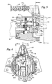
- Yoke 104 has a recess 106 having a diametral dimension 144 sized to fit to the outer race of bearing 102 in a slip or sliding fit. Yoke 104 further has an elongated slot 108 to receive a bushing 110 and an extension 101 of output shaft 98, which may be seen most clearly in Figures 5 and 6. Yoke 104 has an extension or pintle 112, extending therefrom. Pintle 112 is preferably cylindrical and has a diameter 114 less than the width 116 of the narrowest portion of slot 74 (see Fig. 2). Yoke 104 has a body portion 105 intermediate the extension 112 and a piston engaging connection 134.
- the body portion 105 of yoke 104 has a pair of shoe portions 66, 68 which are opposed to or facing each other, and spaced apart the diametral distance 144.
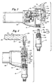
- Yoke 104 is installed by moving it transversely along the direction indicated by arrow 118 in Figure 3 until it is in the position shown in Figure 4.
- a bushing 120 is preferably pressed into a recess 122 in the yoke support portion 124 of handle 22.
- Cylindrical projection or shoulder 126 on removable support 124 is preferably sized to closely inter-fit with the circular portion of key hole slot 74 to align the yoke 104 for reciprocation along axis 78.
- pintle 112 is guided in a sliding bearing or sleeve bushing 120 which is centered by projection 126 in slot 74, as may be seen most clearly in Figure 6.
- shoe portions 66 and 68 of yoke 104 engage the eccentric (via the bearing 102) in a region in alignment with the axis of reciprocation 78, such that the prime mover will rotate the eccentric and reciprocate the yoke 104 by driving the shoe portions 66, 68 alternately back and forth along the axis of reciprocation 78.
- Bushing 110 riding in the slot 108 provides additional guidance for yoke 104 to maintain alignment along axis 78.
- Fluid section 12 is installed in housing 16 by interengaging threads 128 and threads 130 until a piston 132 is received in the recess or piston engaging connection 134 in yoke 104.
- a transverse pin 136 is then inserted into aligned mating apertures 138, 140 in the yoke 104 and piston 132, respectively.
- a spring clip 142 is then placed on yoke 104 to retain pin 136 in mating apertures 138, 140, all as shown in Figure 4.
- a lock nut 146 on fluid section 12 may be used to secure fluid section 12 to housing 16 in the desired alignment.
- the yoke support may be formed without handle 22, and may still be further modified by the omission of bushing 120, if desired, while still remaining within the scope of the invention.
Landscapes
- Engineering & Computer Science (AREA)
- General Engineering & Computer Science (AREA)
- Mechanical Engineering (AREA)
- Reciprocating Pumps (AREA)
Description
Claims (16)
- A portable piston paint pump having a reciprocating member (104) slideably supported in a housing (16) as a part of a rotary to reciprocating motion converting mechanism, comprising:a) a slot (74) in the housing (16) perpendicular to an axis of reciprocation of the reciprocating member (104) ;b) an extension (112) on the reciprocating member (104) extending through the slot (74) and projecting beyond the housing (16); andc) a removable support (124) secured to the housing (16) and aligned with the extension (112) of the reciprocating member (104) to support the extension (112) of the reciprocating member (104) in alignment with the housing (16) and wherein the removable support (124) allows installation and removal of the reciprocating member (104) by providing clearance for the extension (112) via the slot (74) when the removable support (124) is removed.
- The pump of claim 1 wherein the reciprocating member (104) is a Scotch yoke.
- The pump of claim 2 wherein the yoke (104) is formed of a nickel-aluminum-bronze alloy.
- The pump of one of claims 1 to 3 wherein the removable support (124) further comprises a bearing (120).
- The pump of claim 4 wherein the bearing (120) is a sleeve bushing.
- The pump of claim 1 wherein the slot (74) has an enlarged portion and the removable support (124) includes a shoulder (126) received in the enlarged portion of the slot (74) to locate the support (124) with respect to the housing.
- The pump of claim 1 wherein the removable support (124) further includes a handle (22) for lifting the portable piston paint pump.
- A method of installing a reciprocating member (104) in a portable piston paint pump comprising the steps of:a) aligning the reciprocating member (104) parallel to and spaced apart from an axis (78) of reciprocation of a housing (16) of the pump;b) moving the reciprocating member (104) perpendicularly to the axis (78) of reciprocation through a slot (74) in the housing (16) until the reciprocating member (104) engages a rotatable eccentric (100) adapted to reciprocate the receiprocating member;c) moving a removable support (124) along the axis (78) of reciprocation towards the reciprocating member (104) projecting through the slot (74) until the support (124) engages the reciprocating member (104) and contacts the housing (16) ; andd) securing the removable support (124) to the housing (16) to maintain the reciprocating member (104) in alignment with the axis (78) of reciprocation.
- The method of claim 8 further comprising the additional steps of:e) engaging a piston (132) with a portion (134) of the reciprocating member (104) distal of the removable support (124) by moving a fluid section (12) carrying the piston (132) along the axis (78) of reciprocation towards the reciprocating member (104); andf) engaging the fluid section (12) with the housing (16) to maintain the fluid section in alignment with the axis (78) of reciprocation.
- The method of claim 8 wherein the removable support (124) includes a bushing (120) and wherein step c) further comprises engaging the bushing (120) with the reciprocating member (104).
- The method of one of claims 8 to 10 wherein step d) further comprises engaging a shoulder (126) on the support (124) with a mating recess in the housing (16) to maintain the reciprocating member (104) in alignment with the axis (78) of reciprocation.
- The method of claim 11 wherein step d) still further comprises installing and tightening at least one threaded fastener projecting through the support (124) and threadably received in the housing (16) to secure the support to the housing.
- The pump of one of claims 1 to 7, wherein the reciprocating mechanism is a Scotch yoke and comprises:a) a prime mover (96, 88) having an output shaft (98) selectively rotatable about an axis (99) of rotation;b) an eccentric assembly (100, 102) carried on the output shaft (98) and having a shaft extension (101) projecting in alignment with the axis (99) of rotation of the output shaft;c) a Scotch yoke type reciprocatable member (104) located along the axis (78) of reciprocation perpendicular to the axis (99) of rotation and havingsuch that the prime mover (96, 88) rotates the eccentric assembly (100, 102) and reciprocates the reciprocatable member (104) by driving the shoe portions (66, 68) alternately back and forth along the axis (78) of reciprocation.i) an extension (112) at one end thereof aligned with the axis (78) of reciprocation,ii) a piston-engaging connection (134) at the other end thereof, andiii) a body portion (105) mediate the extension (112) and the piston-engaging connection (134) and carrying a slot (108) through which the shaft extension (101) projects, the body portion having a pair of opposed shoe portions (66, 68), each of which engages a region of the eccentric assembly (100, 102) in alignment with the axis (78) of reciprocation
- The pump of one of claims 1 to 5 or 13 wherein the slot (74) in the housing (16) further comprises an enlarged cylindrical recess concentric to the axis (78) of reciprocation and wherein the removable support (124) further comprises a cylindrical projection (126) congruent to and received in the cylindrical recess to positively locate the removable support (124) with respect to the axis (78) of reciprocation.
- The pump of one of claims 1 to 7, 13 or 14 wherein the eccentric assembly (100, 102) further comprises an eccentric member (100) surrounded by an anti-friction bearing (102) engaging the shoe portions (66, 68) of the body (105) of the yoke.
- The pump of one of claims 1 to 7 or 13 to 15 comprising a fluid section (12) for pressurizing paint to which a paint spray gun is connected for atomizing paint to be applied to a surface.
Applications Claiming Priority (3)
| Application Number | Priority Date | Filing Date | Title |
|---|---|---|---|
| US08/594,024 US5769321A (en) | 1996-02-20 | 1996-02-20 | Yoke support for piston paint pumps |
| US594024 | 1996-02-20 | ||
| PCT/US1996/016971 WO1997031186A1 (en) | 1996-02-20 | 1996-10-23 | Yoke support for piston paint pumps |
Publications (2)
| Publication Number | Publication Date |
|---|---|
| EP0882182A1 EP0882182A1 (en) | 1998-12-09 |
| EP0882182B1 true EP0882182B1 (en) | 2001-10-04 |
Family
ID=24377209
Family Applications (1)
| Application Number | Title | Priority Date | Filing Date |
|---|---|---|---|
| EP96936876A Expired - Lifetime EP0882182B1 (en) | 1996-02-20 | 1996-10-23 | Yoke support for piston paint pumps |
Country Status (5)
| Country | Link |
|---|---|
| US (1) | US5769321A (en) |
| EP (1) | EP0882182B1 (en) |
| JP (1) | JP2000505170A (en) |
| DE (1) | DE69615710D1 (en) |
| WO (1) | WO1997031186A1 (en) |
Families Citing this family (33)
| Publication number | Priority date | Publication date | Assignee | Title |
|---|---|---|---|---|
| EP1635062B1 (en) | 1999-08-31 | 2012-06-13 | Graco Minnesota Inc. | Airless spray pump |
| US6752067B1 (en) * | 1999-08-31 | 2004-06-22 | Graco Minnesota Inc. | Airless spray pump |
| EP1208287B1 (en) | 1999-08-31 | 2006-07-26 | Graco Minnesota Inc. | Airless spray pump |
| US6435846B1 (en) | 1999-10-22 | 2002-08-20 | Wagner Spray Tech Corporation | Piston pump having housing with a pump housing and a pump assembly drive housing formed therein |
| CA2387061C (en) * | 1999-10-22 | 2009-08-11 | Wagner Spray Tech Corporation | Piston pump |
| US6419456B1 (en) | 1999-10-22 | 2002-07-16 | Wagner Spray Tech Corporation | Switch for controlling the motor of a piston pump |
| US6467394B1 (en) * | 2000-08-14 | 2002-10-22 | Devilbiss Air Power Company | Oilless high pressure pump |
| US6779987B2 (en) * | 2000-08-14 | 2004-08-24 | Devilbiss Air Power Company | Pressure washer having oilless high pressure pump |
| US6488846B1 (en) * | 2001-06-12 | 2002-12-03 | Rudy Marangi | Paint sprayer filter system |
| US8147226B2 (en) * | 2006-02-01 | 2012-04-03 | Black & Decker Inc. | Valve assembly for pressure washer pump |
| US8182247B2 (en) * | 2008-05-27 | 2012-05-22 | Txam Pumps Llc | Pump with stabilization component |
| US20100072300A1 (en) * | 2008-09-24 | 2010-03-25 | Miller William S | Paint sprayer |
| US9545643B2 (en) | 2008-10-22 | 2017-01-17 | Graco Minnesota Inc. | Portable airless sprayer |
| US8596555B2 (en) | 2008-10-22 | 2013-12-03 | Graco Minnesota Inc. | Portable airless sprayer |
| USD616065S1 (en) | 2008-11-25 | 2010-05-18 | Graco Minnesota Inc. | Paint sprayer |
| USD596706S1 (en) | 2008-11-25 | 2009-07-21 | Graco Minnesota Inc. | Paint sprayer |
| US8651397B2 (en) * | 2009-03-09 | 2014-02-18 | Techtronic Power Tools Technology Limited | Paint sprayer |
| USD632762S1 (en) * | 2009-05-21 | 2011-02-15 | Graco Minnesota Inc. | Airless paint sprayer |
| USD639390S1 (en) * | 2010-10-27 | 2011-06-07 | Sk & Y Agricultural Equipments Co., Ltd. | Spray gun |
| CA2983096C (en) * | 2015-05-01 | 2024-11-12 | Graco Minnesota Inc. | Pump transmission carriage assembly |
| WO2016179015A1 (en) | 2015-05-01 | 2016-11-10 | Graco Minnesota Inc. | Two piece pump rod |
| US12140140B2 (en) * | 2016-07-29 | 2024-11-12 | Wagner Spray Tech Corporation | Aligning reciprocating motion in fluid delivery systems |
| US11007545B2 (en) | 2017-01-15 | 2021-05-18 | Graco Minnesota Inc. | Handheld airless paint sprayer repair |
| EP3762151B1 (en) | 2018-03-19 | 2024-08-21 | Wagner Spray Tech Corporation | Handheld fluid sprayer |
| EP3774069A1 (en) | 2018-04-10 | 2021-02-17 | Graco Minnesota Inc. | Handheld airless sprayer for paints and other coatings |
| TWI855085B (en) | 2019-05-31 | 2024-09-11 | 美商葛萊兒明尼蘇達股份有限公司 | Handheld fluid sprayer |
| USD937387S1 (en) * | 2019-12-31 | 2021-11-30 | Graco Minnesota Inc. | Compact spray gun |
| US10968903B1 (en) | 2020-06-04 | 2021-04-06 | Graco Minnesota Inc. | Handheld sanitary fluid sprayer having resilient polymer pump cylinder |
| US10926275B1 (en) | 2020-06-25 | 2021-02-23 | Graco Minnesota Inc. | Electrostatic handheld sprayer |
| USD1106268S1 (en) * | 2022-03-03 | 2025-12-16 | Wagner Spray Tech Co. | Paint pump housing |
| USD1069985S1 (en) * | 2023-01-10 | 2025-04-08 | Graco Minnesota Inc. | Spray gun system |
| USD1088052S1 (en) * | 2023-11-06 | 2025-08-12 | Wagner Spray Tech Corporation | Fluid pump |
| USD1096853S1 (en) * | 2023-11-06 | 2025-10-07 | Wagner Spray Tech Corporation | Fluid pump |
Family Cites Families (15)
| Publication number | Priority date | Publication date | Assignee | Title |
|---|---|---|---|---|
| US3288079A (en) * | 1964-09-24 | 1966-11-29 | Technicon Chromatography Corp | Pump |
| US3317141A (en) * | 1964-10-26 | 1967-05-02 | Mann Carl | Airless liquid spray gun having a diaphragm pump and filtering apparatus |
| US3904116A (en) * | 1975-01-09 | 1975-09-09 | Disston Inc | Portable cordless sprayer |
| US4184817A (en) * | 1977-12-01 | 1980-01-22 | Lear Siegler, Inc. | High pressure multi-cylinder pump |
| GB2044895B (en) * | 1979-03-16 | 1983-04-20 | Metering Pumps Ltd | Adjustable control |
| US4397610A (en) * | 1981-03-09 | 1983-08-09 | Graco Inc. | Reciprocable pump with variable speed drive |
| US4900233A (en) * | 1988-06-02 | 1990-02-13 | Sundstrand Corporation | Reciprocating compressor providing a lubricant free compressed gas |
| US5092185A (en) * | 1988-07-27 | 1992-03-03 | Balanced Engines, Inc. | Scotch yoke mechanism and power transfer system |
| US5248089A (en) * | 1988-08-15 | 1993-09-28 | Wagner Spray Tech Corporation | Combination carrying case/paint container |
| GB2229617B (en) * | 1989-04-14 | 1993-10-27 | Lin Hsien Chih | Rechargeable garden sprayer |
| US5211611A (en) * | 1989-08-01 | 1993-05-18 | American Power Equipment Company | Planocentric drive mechanism |
| US5244351A (en) * | 1992-09-30 | 1993-09-14 | Textron Inc. | System for protecting a liquid pump |
| US5292232A (en) * | 1993-01-19 | 1994-03-08 | Graco Inc. | Liquid pump pressure control system |
| US5303847A (en) * | 1993-04-05 | 1994-04-19 | Talk To Me Products, Inc. | Toy dispersing water from fingertip sheath |
| US5417309A (en) * | 1993-11-08 | 1995-05-23 | Brackett; Douglas C. | Lubrication system for a conjugate drive mechanism |
-
1996
- 1996-02-20 US US08/594,024 patent/US5769321A/en not_active Expired - Fee Related
- 1996-10-23 JP JP9530117A patent/JP2000505170A/en active Pending
- 1996-10-23 EP EP96936876A patent/EP0882182B1/en not_active Expired - Lifetime
- 1996-10-23 WO PCT/US1996/016971 patent/WO1997031186A1/en not_active Ceased
- 1996-10-23 DE DE69615710T patent/DE69615710D1/en not_active Expired - Lifetime
Also Published As
| Publication number | Publication date |
|---|---|
| JP2000505170A (en) | 2000-04-25 |
| WO1997031186A1 (en) | 1997-08-28 |
| DE69615710D1 (en) | 2001-11-08 |
| US5769321A (en) | 1998-06-23 |
| EP0882182A1 (en) | 1998-12-09 |
Similar Documents
| Publication | Publication Date | Title |
|---|---|---|
| US5769321A (en) | Yoke support for piston paint pumps | |
| EP2104777B1 (en) | Hydraulic tool with wobble plate transmission | |
| US20260085713A1 (en) | Hydraulic power tool | |
| US6193475B1 (en) | Compressor assembly | |
| US6213725B1 (en) | Compressor having an improved piston | |
| KR100341699B1 (en) | Portable tool with variable displacement hydraulic pump | |
| US6668613B2 (en) | Hydraulic compression tool and hydraulic compression tool motor | |
| US5794515A (en) | Swashplate control system for an axial piston pump | |
| US8177524B1 (en) | Manual locking clamp for piston paint pump | |
| US6135144A (en) | Pressure relief valve assembly | |
| JP3238784B2 (en) | Oil pump for chainsaw | |
| EP0297731A2 (en) | Pump with variable angle wobble plate | |
| US20030084556A1 (en) | Pump plunger installation tool | |
| CN109108612B (en) | Semi-automatic press fitting tool | |
| GB2359861A (en) | Hydraulic pump with ball joint shaft support | |
| US4968230A (en) | Lubricating-oil pump control | |
| CN211116444U (en) | Radial plunger pump | |
| US6327961B1 (en) | Connecting rod with integral grease reservoir and bleed hole | |
| US5848566A (en) | Connecting pin clip | |
| EP2280169B1 (en) | Airless spray pump | |
| US20020178907A1 (en) | Air compressor having a smooth and stable structure | |
| US20040165798A1 (en) | Eccentric bearing for a poppet drive system | |
| JP3163266B2 (en) | Stroke adjustment device for reciprocating pump | |
| US6401594B1 (en) | Connecting rod with integral grease reservoir | |
| JPS597589Y2 (en) | plunger pump |
Legal Events
| Date | Code | Title | Description |
|---|---|---|---|
| PUAI | Public reference made under article 153(3) epc to a published international application that has entered the european phase |
Free format text: ORIGINAL CODE: 0009012 |
|
| 17P | Request for examination filed |
Effective date: 19980814 |
|
| AK | Designated contracting states |
Kind code of ref document: A1 Designated state(s): DE |
|
| GRAG | Despatch of communication of intention to grant |
Free format text: ORIGINAL CODE: EPIDOS AGRA |
|
| GRAG | Despatch of communication of intention to grant |
Free format text: ORIGINAL CODE: EPIDOS AGRA |
|
| GRAG | Despatch of communication of intention to grant |
Free format text: ORIGINAL CODE: EPIDOS AGRA |
|
| GRAH | Despatch of communication of intention to grant a patent |
Free format text: ORIGINAL CODE: EPIDOS IGRA |
|
| 17Q | First examination report despatched |
Effective date: 20001208 |
|
| GRAH | Despatch of communication of intention to grant a patent |
Free format text: ORIGINAL CODE: EPIDOS IGRA |
|
| GRAA | (expected) grant |
Free format text: ORIGINAL CODE: 0009210 |
|
| AK | Designated contracting states |
Kind code of ref document: B1 Designated state(s): DE |
|
| REF | Corresponds to: |
Ref document number: 69615710 Country of ref document: DE Date of ref document: 20011108 |
|
| PG25 | Lapsed in a contracting state [announced via postgrant information from national office to epo] |
Ref country code: DE Free format text: LAPSE BECAUSE OF FAILURE TO SUBMIT A TRANSLATION OF THE DESCRIPTION OR TO PAY THE FEE WITHIN THE PRESCRIBED TIME-LIMIT Effective date: 20020105 |
|
| PLBE | No opposition filed within time limit |
Free format text: ORIGINAL CODE: 0009261 |
|
| STAA | Information on the status of an ep patent application or granted ep patent |
Free format text: STATUS: NO OPPOSITION FILED WITHIN TIME LIMIT |
|
| 26N | No opposition filed |