EP0881721A2 - Connector and method of attaching a wire thereto - Google Patents
Connector and method of attaching a wire thereto Download PDFInfo
- Publication number
- EP0881721A2 EP0881721A2 EP98303157A EP98303157A EP0881721A2 EP 0881721 A2 EP0881721 A2 EP 0881721A2 EP 98303157 A EP98303157 A EP 98303157A EP 98303157 A EP98303157 A EP 98303157A EP 0881721 A2 EP0881721 A2 EP 0881721A2
- Authority
- EP
- European Patent Office
- Prior art keywords
- slot
- wire
- terminal
- jig
- connector
- Prior art date
- Legal status (The legal status is an assumption and is not a legal conclusion. Google has not performed a legal analysis and makes no representation as to the accuracy of the status listed.)
- Withdrawn
Links
- 238000000034 method Methods 0.000 title claims description 10
- 238000009413 insulation Methods 0.000 abstract description 2
- 230000000694 effects Effects 0.000 description 2
- 239000002184 metal Substances 0.000 description 2
- 238000005452 bending Methods 0.000 description 1
- 238000002788 crimping Methods 0.000 description 1
- 238000010586 diagram Methods 0.000 description 1
- 238000003780 insertion Methods 0.000 description 1
- 230000037431 insertion Effects 0.000 description 1
- 230000002265 prevention Effects 0.000 description 1
- 229920003002 synthetic resin Polymers 0.000 description 1
- 239000000057 synthetic resin Substances 0.000 description 1
Images


Classifications
-
- H—ELECTRICITY
- H01—ELECTRIC ELEMENTS
- H01R—ELECTRICALLY-CONDUCTIVE CONNECTIONS; STRUCTURAL ASSOCIATIONS OF A PLURALITY OF MUTUALLY-INSULATED ELECTRICAL CONNECTING ELEMENTS; COUPLING DEVICES; CURRENT COLLECTORS
- H01R43/00—Apparatus or processes specially adapted for manufacturing, assembling, maintaining, or repairing of line connectors or current collectors or for joining electric conductors
- H01R43/01—Apparatus or processes specially adapted for manufacturing, assembling, maintaining, or repairing of line connectors or current collectors or for joining electric conductors for connecting unstripped conductors to contact members having insulation cutting edges
-
- H—ELECTRICITY
- H01—ELECTRIC ELEMENTS
- H01R—ELECTRICALLY-CONDUCTIVE CONNECTIONS; STRUCTURAL ASSOCIATIONS OF A PLURALITY OF MUTUALLY-INSULATED ELECTRICAL CONNECTING ELEMENTS; COUPLING DEVICES; CURRENT COLLECTORS
- H01R4/00—Electrically-conductive connections between two or more conductive members in direct contact, i.e. touching one another; Means for effecting or maintaining such contact; Electrically-conductive connections having two or more spaced connecting locations for conductors and using contact members penetrating insulation
- H01R4/24—Connections using contact members penetrating or cutting insulation or cable strands
- H01R4/2416—Connections using contact members penetrating or cutting insulation or cable strands the contact members having insulation-cutting edges, e.g. of tuning fork type
- H01R4/2445—Connections using contact members penetrating or cutting insulation or cable strands the contact members having insulation-cutting edges, e.g. of tuning fork type the contact members having additional means acting on the insulation or the wire, e.g. additional insulation penetrating means, strain relief means or wire cutting knives
- H01R4/2466—Connections using contact members penetrating or cutting insulation or cable strands the contact members having insulation-cutting edges, e.g. of tuning fork type the contact members having additional means acting on the insulation or the wire, e.g. additional insulation penetrating means, strain relief means or wire cutting knives the contact members having a channel-shaped part, the opposite sidewalls of which comprise insulation-cutting means
-
- Y—GENERAL TAGGING OF NEW TECHNOLOGICAL DEVELOPMENTS; GENERAL TAGGING OF CROSS-SECTIONAL TECHNOLOGIES SPANNING OVER SEVERAL SECTIONS OF THE IPC; TECHNICAL SUBJECTS COVERED BY FORMER USPC CROSS-REFERENCE ART COLLECTIONS [XRACs] AND DIGESTS
- Y10—TECHNICAL SUBJECTS COVERED BY FORMER USPC
- Y10T—TECHNICAL SUBJECTS COVERED BY FORMER US CLASSIFICATION
- Y10T29/00—Metal working
- Y10T29/49—Method of mechanical manufacture
- Y10T29/49002—Electrical device making
- Y10T29/49117—Conductor or circuit manufacturing
- Y10T29/49174—Assembling terminal to elongated conductor
- Y10T29/49181—Assembling terminal to elongated conductor by deforming
- Y10T29/49185—Assembling terminal to elongated conductor by deforming of terminal
- Y10T29/49188—Assembling terminal to elongated conductor by deforming of terminal with penetrating portion
- Y10T29/4919—Through insulation
Definitions
- the present invention relates to an electrical connector, and to a pressure contact method for attaching an electric wire thereto.
- Figures 5 and 6 of this specification show a connector which permits the electrical connection of a terminal fitting 41 and an electric wire 42.
- the electric wire 42 is inserted from above by means of a jig 44 into the terminal fitting 41 which is installed within a connector housing 40.
- the terminal fitting 41 employed in this type of connector has pressure contact blades 43 facing inwards from both sides of the central portion, the insulated electric wire 42 being pressed onto the blades 43 from above. When this pressing-in occurs, the core of the electric wire 42 and a portion of the pressure contact blades 43 come into contact since the blades 43 cut into the insulated covering.
- the present invention has been developed after taking the above problem into consideration, and aims to provide a connector and a pressure contact method for attaching an electric wire to a terminal fitting in which the widening of the terminal fitting is controlled at the time when the electric wire is pressed in.
- an electrical connector comprising a housing having a cavity therein, and an electrical terminal within said cavity, the terminal having blade members defining a slot to receive an electrical wire by pressure contact wherein said terminal is adapted for direct engagement with an assembly jig in the vicinity of said blade members whereby as said jig pushes a wire into said slot, said blade members are held against mutual outward movement tending to widen said slot.
- Such a connector has the advantage that the wire receiving slot is not widened on entry of the wire. Accordingly, the electrical connection is improved, and the terminal may be made of a thinner metal gauge.
- the blade members protrude from the housing so as to permit direct engagement with an assembly jig.
- the side walls of a connector housing may be cut away to facilitate this protrusion.
- the assembly jig includes depending limbs to both engage the blade members, and to push a wire into the slot.
- one limb may support blade members of adjacent terminals. These support limbs are preferably spring loaded and having a form locking engagement with the connector housing.
- the invention also provides a method of inserting a wire into a slot of a blade connector, the method comprising the steps of placing a wire over the slot, engaging the terminal in the vicinity of the blade members so as to prevent widening of the slot and pushing a wire into said slot.
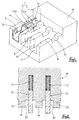
- Figure 1 is a diagonal view of a present embodiment showing a terminal fitting fitted to a connector housing.
- Figure 2 is a cross-sectional view through a pressure contact mould.
- Figure 3 is a partial cross-sectional view of the terminal fitting before an electric wire is pressed in.
- Figure 4 is a partial cross-sectional view of the terminal fitting after the electric wire is pressed in.
- Figure 5 is a partial cross-sectional view of a prior art example showing a terminal fitting before an electric wire is pressed in.
- Figure 6 is a partial cross-sectional view of the prior art example showing the terminal fitting after the electric wire is pressed in.
- a connector 1 shown in Figure 1 comprises a connector housing 2, a terminal fitting 7 and a cover (not shown) which is attached to the connector housing 2 from above.
- the female connector housing 2 is formed in a unified manner from synthetic resin in a schematically rectangular parallelepiped shape.
- the female terminal fitting 7 is attached to the female connector housing 2 which fits with a male connector housing (not shown). That is, the connector housing 2 is formed in such a way that the anterior portion is larger than the posterior portion, and that it has a hood member 6 which can be fitted with the corresponding male connector housing.
- the posterior end is open from above and its interior is divided into three cavities 5 by walls 9. Each cavity 5 houses a terminal fitting 7.
- the anterior ends of these terminal fittings 7 are not shown, but they are inserted into the hood member 6 as far as the anterior end thereof so as to be able to make contact with the terminal fittings housed within a corresponding connector housing.
- Cut-out portions 8 are formed on that section of the walls 9 where pressure contact blades 14A and 14B (to be described later) of the terminal fitting 7 are located, a portion of a pressure contact member 14 protruding beyond the cut-away walls 9. Further, the posterior ends of the walls 9 have relatively wide jig grooves 10 formed at the location of a barrel member 13 of the terminal fitting 7. When the terminal fitting 7 (to be explained below) is fixed into the cavity 5, the jig groove 10 is the only portion where a space occurs between the terminal fitting 7 and the cavity 5.
- the connector housing 2 can be fitted with a removable cover to close off each cavity 5.
- the terminal fitting 7 is formed from an electrically conductive metal plate which is bent by means of a press process.
- the anterior portion of the terminal fitting 7 has a contact member (not shown) which makes contact with a corresponding terminal fitting (also not shown), and the posterior portion has a barrel member 13 for making pressure contact with a wire 15.
- the barrel member 13 comprises a pair of left and right protrusions mutually displaced in the anterior-posterior direction, the upper edge of these protrusions being bent slight toward the interior.
- a crimping device (not shown) known as a crimper is inserted from above between the jig groove 10 and the barrel member 13, the bending of the aforementioned left and right protrusions facilitating this insertion.
- the central portion of the terminal fitting 7 is provided with a pressure contact member 14 which serves to effect pressure contact between the terminal fitting 7 and the electric wire 15.
- This pressure contact member 14 has a pair of left and right pressure contact blades 14A and 14B in the anterior-posterior direction on both sides of the terminal fitting 7. These pressure contact blades 14A and 14B are formed by being cut out from both side faces of the pressure contact member 14. Further, the pressure contact blades 14A and 14B form a pair separated by a specified distance and face one another, the facing edges having sharp blades and forming a slot 4. When the electric wire 15 presses down on the slot 4, the blades cut into the insulation 16 as far as the core wire 17, thus bringing the core wire 17 into contact with the pressure contact blades 14A and 14B (see Figures 3 and 4).
- the present embodiment employs a pressure contact mould 18 (see Figure 2) which can be raised and lowered.
- the pressure contact mould 18 has three horizontal columns formed in a parallel manner so as to correspond to the cavities 5. This allows the pressure contact operation to be performed simultaneously on the electric wires 15 with respect to each terminal fitting 7.
- Three pressing protrusions 19 are formed on the lower face of the pressure contact mould 18 which push the electric wire 15 in the direction of the terminal fitting 7.
- Each pressing protrusion 19 is formed so as to be slightly longer than at least the space in the anterior-posterior direction between the pressure contact blades 14A and 14B of the terminal fitting 7.
- the pressing protrusions 19 have a cut-away portion 23 in that position where the pressing protrusions 19 would otherwise make contact against the pressure contact blades 14A and 14B as a result of the pressure contact mould 18 being lowered. Consequently, at the time of the pressing operation, an impact is avoided between the pressing protrusions 19 and the pressure contact blades 14A and 14B, and the pressing protrusions 19 can push the electric wire 15 deeply into the pressure contact blades 14A and 14B.
- each pressing protrusion 19 On the lower face of the pressure contact mould 18 and on both sides of each pressing protrusion 19 are a pair of pressing members 20 which constitute a widening prevention member of the present invention, and which protrude further downwards than the pressing protrusions 19.
- These pressing members 20 are formed separately from the pressing protrusions 19 and are attached to the lower side of springs 21 located within groove members 22 of the main body of the pressure contact mould 18, the springs 21 pushing the pressing members 20 downwards.
- These pressing members 20 are attached in such a way that they can be pressed into the groove members 22.
- the pressing members 20 are provided directly above the cut-out portions 8 formed on the corresponding cut-away walls 9.
- the pressing members 20 When the electric wires 15 are pushed downwards by the pressing protrusions 19, the pressing members 20 come into contact with the outer sides of both side faces of the pressure contact member 14 of the terminal fitting 7, and the lower edges of the pressing protrusions 19 on the lower side of the pressure contact mould 18 make contact with the upper edges of the cut-away walls 9. In this manner, the pressing protrusions 19 surround both side faces of the pressure contact member 14 from the outside and thereby control the widening of the side faces of the pressure contact member 14.
- the pair of pressing members 20 When the pressure contact mould 18 is pushed onto the terminal fitting 7, the pair of pressing members 20 first surround the side faces of the pressure contact member 14 of the terminal fitting 7. Next, since the pressing members 20 make contact with the cut-away wall 9, they are pushed in the direction of the groove member 22. Finally, the pressing protrusion 19 pushes the electric wire 15 in the direction of the pressure contact member 14. At this juncture, the widening of the terminal fittings 7 is controlled because the pressing members 20 are holding the side walls of the pressure contact member 14 in a fixed position. After the pressing operation of the electric wires 15 is completed, the pressure contact mould 18 is raised and the return of the pressing members 20 to their original position is effected by the springs 21.
- the connector 1 is completed by attaching a cover (not shown) to the connector housing 2 from above.
- the pressure contact mould 18 is employed to press the electric wire 15 into the slot 4 of the terminal fitting 7 which is attached within the cavity 5 of the connector housing 2.
- the pressing-in operation of the electric wire 15 is performed after the pressing members 20 provided on the pressure contact mould 18 join with the cut-out portions 8 inside the side faces of the pressure contact member 14.
- the terminal fitting 7 does not widen when the electric wire 15 is pressed in. Consequently, an effective pressing connecting force can be maintained between the core wire 17 and the terminal fitting 7.
- the pressing members 20 join with the external sides of the pressure contact member 14 at the time of the pressing-in operation of the electric wire 15, the electric wire 15 can be pressed in and the widening of the terminal fitting 7 can be controlled all in a single operation.
Abstract
Description
Claims (10)
- An electrical connector comprising a housing (2) having a cavity (5) therein, and an electrical terminal (7) within said cavity (5), the terminal (7) having blade members (14A,14B) defining a slot (4) to receive an electrical wire (15) by pressure contact wherein said terminal (7) is adapted for direct engagement with an assembly jig (18) in the vicinity of said blade members (14A,14B) whereby as said jig pushes a wire into said slot, said blade members (14A,14B) are held against mutual outward movement tending to widen said slot (4).
- A connector according to claim 1 wherein said terminal (7) is exposed in said cavity (5) in the vicinity of said blade members (14A,14B).
- A connector according to claim 2 wherein said cavity comprises a recess having a base and two upstanding side walls, the upper edges of said side walls being cut away in the vicinity of said blade members (14A,14B) to permit engagement in use of said terminal (7) by an assembly jig (18).
- A connector according to claim 3 wherein said walls have a respective recess (8) in the upper edges thereof, said recesses (8) extending through the thickness of said walls.
- In combination, an electrical connector according to any preceding claim and an assembly jig (18), said jig having a first limb (19) adapted to urge a wire into said slot, and second limbs (20) adapted to engage the outer sides of said terminal (7) in the vicinity of respective blade members (14A,14B) to prevent widening of said slot.
- The combination of claim 5 wherein said second limbs (20) are resiliently urged in the direction of the axis of said slot.
- The combination of claim 5 or claim 6 wherein said connector has a plurality of aligned terminals (7), and opposite sides of a second limb (20) of said jig are adapted to engage adjacent terminals in the vicinity of blade members thereof.
- A method of inserting a wire into a blade connector comprising a connector housing and a terminal within said housing, said terminal having opposed blade members defining a wire-receiving slot, the method comprising the steps ofplacing a wire over said slot;engaging said terminal with a jig in the vicinity of said blade members to prevent widening of said slot; andpushing said wire into said slot with said jig.
- A method according to claim 8 and including the step of interlocking said jig and said connector prior to pushing the wire into said slot.
- A method according to claim 8 or claim 9 and including the step of providing the jig with support members to engage said terminal, and a pushing member to push said wire, said support members being movable relative to said pushing member as the wire is pushed into said slot.
Applications Claiming Priority (3)
| Application Number | Priority Date | Filing Date | Title |
|---|---|---|---|
| JP13720697A JP3303724B2 (en) | 1997-05-27 | 1997-05-27 | Pressure welding method of electric wires to connectors and terminal fittings |
| JP137206/97 | 1997-05-27 | ||
| JP13720697 | 1997-05-27 |
Publications (2)
| Publication Number | Publication Date |
|---|---|
| EP0881721A2 true EP0881721A2 (en) | 1998-12-02 |
| EP0881721A3 EP0881721A3 (en) | 2000-03-29 |
Family
ID=15193277
Family Applications (1)
| Application Number | Title | Priority Date | Filing Date |
|---|---|---|---|
| EP98303157A Withdrawn EP0881721A3 (en) | 1997-05-27 | 1998-04-23 | Connector and method of attaching a wire thereto |
Country Status (4)
| Country | Link |
|---|---|
| US (1) | US6176731B1 (en) |
| EP (1) | EP0881721A3 (en) |
| JP (1) | JP3303724B2 (en) |
| CN (1) | CN1211090A (en) |
Cited By (2)
| Publication number | Priority date | Publication date | Assignee | Title |
|---|---|---|---|---|
| EP1207595A2 (en) * | 2000-11-15 | 2002-05-22 | Autonetworks Technologies, Ltd. | Wire press-contact method and method of attaching press-contact terminal to connector housing |
| EP1331706A2 (en) * | 2002-01-24 | 2003-07-30 | J.S.T. Mfg. Co., Ltd. | Insulation displacement apparatus |
Families Citing this family (9)
| Publication number | Priority date | Publication date | Assignee | Title |
|---|---|---|---|---|
| JP3331185B2 (en) | 1999-03-19 | 2002-10-07 | タイコエレクトロニクスアンプ株式会社 | Pressure welding device and pressure welding method |
| JP2001237002A (en) * | 2000-02-22 | 2001-08-31 | Sumitomo Wiring Syst Ltd | Crimp terminal metal fitting |
| SE0302979D0 (en) | 2003-11-12 | 2003-11-12 | Amc Centurion Ab | Antenna device and portable radio communication device including such an antenna device |
| DE102007016070A1 (en) * | 2007-04-03 | 2008-10-09 | Lear Corp., Southfield | Electrical connection arrangement and method for using the electrical connection arrangement |
| JP2010080262A (en) * | 2008-09-26 | 2010-04-08 | Murata Mfg Co Ltd | L-shaped coaxial connector and method for manufacturing the same |
| JP5586354B2 (en) * | 2010-07-15 | 2014-09-10 | 矢崎総業株式会社 | Mold and crimping method |
| CN103269006B (en) * | 2013-05-14 | 2015-04-22 | 罗邦君 | Automatic installation device of switch socket junction box connecting sheet |
| CN107425344B (en) * | 2016-05-23 | 2019-07-16 | 泰科电子(上海)有限公司 | Connector |
| CN108599058B (en) * | 2018-04-24 | 2021-02-23 | 王云森 | Quick termination of circuit fundamental principle teaching |
Citations (6)
| Publication number | Priority date | Publication date | Assignee | Title |
|---|---|---|---|---|
| US3959868A (en) * | 1973-06-14 | 1976-06-01 | Bunker Ramo Corporation | Tool and adapter for electrical connector unit using insulation piercing contacts |
| US5018269A (en) * | 1988-07-14 | 1991-05-28 | Yazaki Corporation | Method for press-installing wires |
| FR2656469A1 (en) * | 1989-12-27 | 1991-06-28 | Francelco Sa | Electrical contact terminal and connector making use of it |
| FR2703520A1 (en) * | 1993-04-02 | 1994-10-07 | Francelco Sa | Electrical connector module and method of fitting such a module |
| US5575061A (en) * | 1994-02-14 | 1996-11-19 | Yazaki Corporation | Wire pressing method and apparatus for pressing a wire into a terminal |
| US5581879A (en) * | 1994-02-25 | 1996-12-10 | Yazaki Corporation | Wire press-fitting method and apparatus for pressure terminal |
Family Cites Families (7)
| Publication number | Priority date | Publication date | Assignee | Title |
|---|---|---|---|---|
| CH301575A (en) | 1950-09-11 | 1954-09-15 | Siemens Reiniger Werke Ag | Method and device for screen observation and radiographic recording of dorsally located parts or organs of the body, in particular the human kidney, with the same body position. |
| US2703520A (en) | 1951-03-12 | 1955-03-08 | Woodlin Metal Products Company | Roof stack |
| US4296988A (en) * | 1980-02-20 | 1981-10-27 | Amp Incorporated | Connector with improved terminal support |
| US4344665A (en) | 1980-10-31 | 1982-08-17 | Amp Incorporated | Connector for mass terminating individual conductors |
| JP2981350B2 (en) | 1992-09-30 | 1999-11-22 | ヒロセ電機株式会社 | Electrical connector positioning device |
| JP3179996B2 (en) * | 1995-02-09 | 2001-06-25 | 矢崎総業株式会社 | Method for manufacturing press-fit joint connector and method for press-fitting electric wire |
| JPH09147956A (en) * | 1995-11-27 | 1997-06-06 | Yazaki Corp | Terminal floating prevention structure |
-
1997
- 1997-05-27 JP JP13720697A patent/JP3303724B2/en not_active Expired - Fee Related
-
1998
- 1998-04-23 EP EP98303157A patent/EP0881721A3/en not_active Withdrawn
- 1998-05-14 CN CN98102148.4A patent/CN1211090A/en active Pending
- 1998-05-19 US US09/081,067 patent/US6176731B1/en not_active Expired - Fee Related
Patent Citations (6)
| Publication number | Priority date | Publication date | Assignee | Title |
|---|---|---|---|---|
| US3959868A (en) * | 1973-06-14 | 1976-06-01 | Bunker Ramo Corporation | Tool and adapter for electrical connector unit using insulation piercing contacts |
| US5018269A (en) * | 1988-07-14 | 1991-05-28 | Yazaki Corporation | Method for press-installing wires |
| FR2656469A1 (en) * | 1989-12-27 | 1991-06-28 | Francelco Sa | Electrical contact terminal and connector making use of it |
| FR2703520A1 (en) * | 1993-04-02 | 1994-10-07 | Francelco Sa | Electrical connector module and method of fitting such a module |
| US5575061A (en) * | 1994-02-14 | 1996-11-19 | Yazaki Corporation | Wire pressing method and apparatus for pressing a wire into a terminal |
| US5581879A (en) * | 1994-02-25 | 1996-12-10 | Yazaki Corporation | Wire press-fitting method and apparatus for pressure terminal |
Cited By (4)
| Publication number | Priority date | Publication date | Assignee | Title |
|---|---|---|---|---|
| EP1207595A2 (en) * | 2000-11-15 | 2002-05-22 | Autonetworks Technologies, Ltd. | Wire press-contact method and method of attaching press-contact terminal to connector housing |
| EP1207595A3 (en) * | 2000-11-15 | 2003-09-03 | Autonetworks Technologies, Ltd. | Wire press-contact method and method of attaching press-contact terminal to connector housing |
| EP1331706A2 (en) * | 2002-01-24 | 2003-07-30 | J.S.T. Mfg. Co., Ltd. | Insulation displacement apparatus |
| EP1331706A3 (en) * | 2002-01-24 | 2004-08-18 | J.S.T. Mfg. Co., Ltd. | Insulation displacement apparatus |
Also Published As
| Publication number | Publication date |
|---|---|
| JPH10326633A (en) | 1998-12-08 |
| US6176731B1 (en) | 2001-01-23 |
| CN1211090A (en) | 1999-03-17 |
| EP0881721A3 (en) | 2000-03-29 |
| JP3303724B2 (en) | 2002-07-22 |
Similar Documents
| Publication | Publication Date | Title |
|---|---|---|
| US4277124A (en) | Connector having wire-in-slot connecting means and crimped strain relief | |
| US4288141A (en) | Insulation displacement contact for an electrical connector | |
| JP2000048888A (en) | Electrical connector | |
| WO1997045896A1 (en) | Surface mountable electrical connector | |
| US6086413A (en) | Multiple wire connector | |
| WO1997008780A1 (en) | Method for making surface mountable connectors | |
| US6176731B1 (en) | Electrical connector housing with cavity and terminal fitting with insulation displacement contact blades and method of attaching a wire thereto | |
| KR100851709B1 (en) | electrical connector | |
| US3842392A (en) | Pre-loaded electrical connectors, assembly apparatus and method | |
| EP0279700B1 (en) | Electrical connector (cut-off through the cover) | |
| EP1134848B1 (en) | A connector and a set of terminal fittings | |
| US4884984A (en) | Crimp connector and method of attaching wire to it | |
| CN1722522B (en) | Electrical wire press-fit type connector | |
| US20220224025A1 (en) | Connection device and connector | |
| CN113169474B (en) | Socket contact element for an electrically conductive connection | |
| EP0926763A1 (en) | Pressure contact terminal fitting with its housing | |
| US4323296A (en) | Connector | |
| US20230119493A1 (en) | Connector and connector manufacturing method | |
| EP1580848A1 (en) | Connector for coaxial cables and electrical connecting system comprising such a connector | |
| US5186658A (en) | Electrical contact | |
| EP0446220B1 (en) | Electrical contact | |
| EP0600402B1 (en) | Electrical connector with improved terminal retention | |
| KR100316079B1 (en) | HF-plug type connector and assembly method of the connector | |
| US4486950A (en) | Method of making two row electrical connector | |
| JPH0548381Y2 (en) |
Legal Events
| Date | Code | Title | Description |
|---|---|---|---|
| PUAI | Public reference made under article 153(3) epc to a published international application that has entered the european phase |
Free format text: ORIGINAL CODE: 0009012 |
|
| 17P | Request for examination filed |
Effective date: 19980504 |
|
| AK | Designated contracting states |
Kind code of ref document: A2 Designated state(s): DE FR GB IT |
|
| AX | Request for extension of the european patent |
Free format text: AL;LT;LV;MK;RO;SI |
|
| PUAL | Search report despatched |
Free format text: ORIGINAL CODE: 0009013 |
|
| AK | Designated contracting states |
Kind code of ref document: A3 Designated state(s): AT BE CH CY DE DK ES FI FR GB GR IE IT LI LU MC NL PT SE |
|
| AX | Request for extension of the european patent |
Free format text: AL;LT;LV;MK;RO;SI |
|
| 17Q | First examination report despatched |
Effective date: 20000626 |
|
| AKX | Designation fees paid |
Free format text: DE FR GB IT |
|
| GRAG | Despatch of communication of intention to grant |
Free format text: ORIGINAL CODE: EPIDOS AGRA |
|
| RTI1 | Title (correction) |
Free format text: ELECTRICAL CONNECTOR AND ASSEMBLY JIG COMBINATION AND METHOD OF ATTACHING A WIRE TO THE CONNECTOR |
|
| GRAG | Despatch of communication of intention to grant |
Free format text: ORIGINAL CODE: EPIDOS AGRA |
|
| GRAG | Despatch of communication of intention to grant |
Free format text: ORIGINAL CODE: EPIDOS AGRA |
|
| GRAH | Despatch of communication of intention to grant a patent |
Free format text: ORIGINAL CODE: EPIDOS IGRA |
|
| GRAH | Despatch of communication of intention to grant a patent |
Free format text: ORIGINAL CODE: EPIDOS IGRA |
|
| STAA | Information on the status of an ep patent application or granted ep patent |
Free format text: STATUS: THE APPLICATION IS DEEMED TO BE WITHDRAWN |
|
| 18D | Application deemed to be withdrawn |
Effective date: 20021205 |