EP0881646B1 - Self-fusible insulated wire - Google Patents
Self-fusible insulated wire Download PDFInfo
- Publication number
- EP0881646B1 EP0881646B1 EP97909622A EP97909622A EP0881646B1 EP 0881646 B1 EP0881646 B1 EP 0881646B1 EP 97909622 A EP97909622 A EP 97909622A EP 97909622 A EP97909622 A EP 97909622A EP 0881646 B1 EP0881646 B1 EP 0881646B1
- Authority
- EP
- European Patent Office
- Prior art keywords
- resin
- bonding
- self
- insulated wire
- nylon
- Prior art date
- Legal status (The legal status is an assumption and is not a legal conclusion. Google has not performed a legal analysis and makes no representation as to the accuracy of the status listed.)
- Expired - Lifetime
Links
- 239000011347 resin Substances 0.000 claims abstract description 72
- 229920005989 resin Polymers 0.000 claims abstract description 72
- 238000002844 melting Methods 0.000 claims abstract description 59
- 229920006122 polyamide resin Polymers 0.000 claims abstract description 40
- 230000008018 melting Effects 0.000 claims abstract description 33
- 239000004677 Nylon Substances 0.000 claims abstract description 27
- 229920001778 nylon Polymers 0.000 claims abstract description 27
- 125000003277 amino group Chemical group 0.000 claims abstract description 20
- 125000003178 carboxy group Chemical group [H]OC(*)=O 0.000 claims abstract description 19
- 229920002302 Nylon 6,6 Polymers 0.000 claims abstract description 9
- 229920003189 Nylon 4,6 Polymers 0.000 claims abstract description 5
- 239000000203 mixture Substances 0.000 claims description 6
- 239000011342 resin composition Substances 0.000 claims description 2
- 238000004804 winding Methods 0.000 abstract description 37
- 239000004020 conductor Substances 0.000 abstract description 11
- 238000004519 manufacturing process Methods 0.000 abstract description 4
- 239000003960 organic solvent Substances 0.000 abstract description 4
- 239000011248 coating agent Substances 0.000 abstract 6
- 238000000576 coating method Methods 0.000 abstract 6
- 230000004927 fusion Effects 0.000 abstract 3
- 239000012212 insulator Substances 0.000 abstract 1
- 239000002966 varnish Substances 0.000 description 41
- 230000000052 comparative effect Effects 0.000 description 25
- RLSSMJSEOOYNOY-UHFFFAOYSA-N m-cresol Chemical compound CC1=CC=CC(O)=C1 RLSSMJSEOOYNOY-UHFFFAOYSA-N 0.000 description 14
- 238000004534 enameling Methods 0.000 description 11
- OKKJLVBELUTLKV-UHFFFAOYSA-N Methanol Chemical compound OC OKKJLVBELUTLKV-UHFFFAOYSA-N 0.000 description 9
- 239000004687 Nylon copolymer Substances 0.000 description 7
- 238000000113 differential scanning calorimetry Methods 0.000 description 7
- 238000000465 moulding Methods 0.000 description 7
- 229920003656 Daiamid® Polymers 0.000 description 5
- JHWNWJKBPDFINM-UHFFFAOYSA-N Laurolactam Chemical compound O=C1CCCCCCCCCCCN1 JHWNWJKBPDFINM-UHFFFAOYSA-N 0.000 description 5
- 229920000299 Nylon 12 Polymers 0.000 description 5
- 239000003822 epoxy resin Substances 0.000 description 5
- 239000000178 monomer Substances 0.000 description 5
- -1 pinene Chemical compound 0.000 description 5
- 229920000647 polyepoxide Polymers 0.000 description 5
- QTWJRLJHJPIABL-UHFFFAOYSA-N 2-methylphenol;3-methylphenol;4-methylphenol Chemical compound CC1=CC=C(O)C=C1.CC1=CC=CC(O)=C1.CC1=CC=CC=C1O QTWJRLJHJPIABL-UHFFFAOYSA-N 0.000 description 4
- CTQNGGLPUBDAKN-UHFFFAOYSA-N O-Xylene Chemical compound CC1=CC=CC=C1C CTQNGGLPUBDAKN-UHFFFAOYSA-N 0.000 description 4
- 239000004959 Rilsan Substances 0.000 description 4
- 238000001816 cooling Methods 0.000 description 4
- 238000000034 method Methods 0.000 description 4
- 239000012046 mixed solvent Substances 0.000 description 4
- ISWSIDIOOBJBQZ-UHFFFAOYSA-N phenol group Chemical group C1(=CC=CC=C1)O ISWSIDIOOBJBQZ-UHFFFAOYSA-N 0.000 description 4
- 239000002904 solvent Substances 0.000 description 4
- 239000008096 xylene Substances 0.000 description 4
- UHOVQNZJYSORNB-UHFFFAOYSA-N Benzene Chemical compound C1=CC=CC=C1 UHOVQNZJYSORNB-UHFFFAOYSA-N 0.000 description 3
- IMNFDUFMRHMDMM-UHFFFAOYSA-N N-Heptane Chemical compound CCCCCCC IMNFDUFMRHMDMM-UHFFFAOYSA-N 0.000 description 3
- 229920002292 Nylon 6 Polymers 0.000 description 3
- 239000004952 Polyamide Substances 0.000 description 3
- HEMHJVSKTPXQMS-UHFFFAOYSA-M Sodium hydroxide Chemical compound [OH-].[Na+] HEMHJVSKTPXQMS-UHFFFAOYSA-M 0.000 description 3
- YXFVVABEGXRONW-UHFFFAOYSA-N Toluene Chemical compound CC1=CC=CC=C1 YXFVVABEGXRONW-UHFFFAOYSA-N 0.000 description 3
- 229930003836 cresol Natural products 0.000 description 3
- 229920001519 homopolymer Polymers 0.000 description 3
- 229920003055 poly(ester-imide) Polymers 0.000 description 3
- 229920002647 polyamide Polymers 0.000 description 3
- 238000003825 pressing Methods 0.000 description 3
- 239000012488 sample solution Substances 0.000 description 3
- CXWXQJXEFPUFDZ-UHFFFAOYSA-N tetralin Chemical compound C1=CC=C2CCCCC2=C1 CXWXQJXEFPUFDZ-UHFFFAOYSA-N 0.000 description 3
- DSEKYWAQQVUQTP-XEWMWGOFSA-N (2r,4r,4as,6as,6as,6br,8ar,12ar,14as,14bs)-2-hydroxy-4,4a,6a,6b,8a,11,11,14a-octamethyl-2,4,5,6,6a,7,8,9,10,12,12a,13,14,14b-tetradecahydro-1h-picen-3-one Chemical compound C([C@H]1[C@]2(C)CC[C@@]34C)C(C)(C)CC[C@]1(C)CC[C@]2(C)[C@H]4CC[C@@]1(C)[C@H]3C[C@@H](O)C(=O)[C@@H]1C DSEKYWAQQVUQTP-XEWMWGOFSA-N 0.000 description 2
- KVNYFPKFSJIPBJ-UHFFFAOYSA-N 1,2-diethylbenzene Chemical compound CCC1=CC=CC=C1CC KVNYFPKFSJIPBJ-UHFFFAOYSA-N 0.000 description 2
- OGRAOKJKVGDSFR-UHFFFAOYSA-N 2,3,5-trimethylphenol Chemical compound CC1=CC(C)=C(C)C(O)=C1 OGRAOKJKVGDSFR-UHFFFAOYSA-N 0.000 description 2
- QWBBPBRQALCEIZ-UHFFFAOYSA-N 2,3-dimethylphenol Chemical compound CC1=CC=CC(O)=C1C QWBBPBRQALCEIZ-UHFFFAOYSA-N 0.000 description 2
- VXSCPERJHPWROZ-UHFFFAOYSA-N 2,4,5-trimethylphenol Chemical compound CC1=CC(C)=C(O)C=C1C VXSCPERJHPWROZ-UHFFFAOYSA-N 0.000 description 2
- NKTOLZVEWDHZMU-UHFFFAOYSA-N 2,5-xylenol Chemical compound CC1=CC=C(C)C(O)=C1 NKTOLZVEWDHZMU-UHFFFAOYSA-N 0.000 description 2
- NXXYKOUNUYWIHA-UHFFFAOYSA-N 2,6-Dimethylphenol Chemical compound CC1=CC=CC(C)=C1O NXXYKOUNUYWIHA-UHFFFAOYSA-N 0.000 description 2
- YCOXTKKNXUZSKD-UHFFFAOYSA-N 3,4-xylenol Chemical compound CC1=CC=C(O)C=C1C YCOXTKKNXUZSKD-UHFFFAOYSA-N 0.000 description 2
- TUAMRELNJMMDMT-UHFFFAOYSA-N 3,5-xylenol Chemical compound CC1=CC(C)=CC(O)=C1 TUAMRELNJMMDMT-UHFFFAOYSA-N 0.000 description 2
- QDQMEHXIUFCIGR-UHFFFAOYSA-N 4-ethyl-2-methylphenol Chemical compound CCC1=CC=C(O)C(C)=C1 QDQMEHXIUFCIGR-UHFFFAOYSA-N 0.000 description 2
- AYGDIAGADYTJRY-UHFFFAOYSA-N 5-ethyl-2-methylphenol Chemical compound CCC1=CC=C(C)C(O)=C1 AYGDIAGADYTJRY-UHFFFAOYSA-N 0.000 description 2
- 239000004953 Aliphatic polyamide Substances 0.000 description 2
- YNQLUTRBYVCPMQ-UHFFFAOYSA-N Ethylbenzene Chemical compound CCC1=CC=CC=C1 YNQLUTRBYVCPMQ-UHFFFAOYSA-N 0.000 description 2
- 239000002253 acid Substances 0.000 description 2
- 230000002411 adverse Effects 0.000 description 2
- 125000002723 alicyclic group Chemical group 0.000 description 2
- 125000001931 aliphatic group Chemical group 0.000 description 2
- 150000001338 aliphatic hydrocarbons Chemical class 0.000 description 2
- 229920003231 aliphatic polyamide Polymers 0.000 description 2
- 239000004760 aramid Substances 0.000 description 2
- 150000004945 aromatic hydrocarbons Chemical class 0.000 description 2
- 229920003235 aromatic polyamide Polymers 0.000 description 2
- 230000015572 biosynthetic process Effects 0.000 description 2
- 229920001577 copolymer Polymers 0.000 description 2
- RWGFKTVRMDUZSP-UHFFFAOYSA-N cumene Chemical compound CC(C)C1=CC=CC=C1 RWGFKTVRMDUZSP-UHFFFAOYSA-N 0.000 description 2
- NNBZCPXTIHJBJL-UHFFFAOYSA-N decalin Chemical compound C1CCCC2CCCCC21 NNBZCPXTIHJBJL-UHFFFAOYSA-N 0.000 description 2
- 238000000354 decomposition reaction Methods 0.000 description 2
- 230000002950 deficient Effects 0.000 description 2
- SNRUBQQJIBEYMU-UHFFFAOYSA-N dodecane Chemical compound CCCCCCCCCCCC SNRUBQQJIBEYMU-UHFFFAOYSA-N 0.000 description 2
- 230000000694 effects Effects 0.000 description 2
- 238000010438 heat treatment Methods 0.000 description 2
- 125000002887 hydroxy group Chemical group [H]O* 0.000 description 2
- XMGQYMWWDOXHJM-UHFFFAOYSA-N limonene Chemical compound CC(=C)C1CCC(C)=CC1 XMGQYMWWDOXHJM-UHFFFAOYSA-N 0.000 description 2
- 239000000314 lubricant Substances 0.000 description 2
- 239000012778 molding material Substances 0.000 description 2
- QWVGKYWNOKOFNN-UHFFFAOYSA-N o-cresol Chemical compound CC1=CC=CC=C1O QWVGKYWNOKOFNN-UHFFFAOYSA-N 0.000 description 2
- TVMXDCGIABBOFY-UHFFFAOYSA-N octane Chemical compound CCCCCCCC TVMXDCGIABBOFY-UHFFFAOYSA-N 0.000 description 2
- IWDCLRJOBJJRNH-UHFFFAOYSA-N p-cresol Chemical compound CC1=CC=C(O)C=C1 IWDCLRJOBJJRNH-UHFFFAOYSA-N 0.000 description 2
- HFPZCAJZSCWRBC-UHFFFAOYSA-N p-cymene Chemical compound CC(C)C1=CC=C(C)C=C1 HFPZCAJZSCWRBC-UHFFFAOYSA-N 0.000 description 2
- 238000006116 polymerization reaction Methods 0.000 description 2
- BGHCVCJVXZWKCC-UHFFFAOYSA-N tetradecane Chemical compound CCCCCCCCCCCCCC BGHCVCJVXZWKCC-UHFFFAOYSA-N 0.000 description 2
- 238000004448 titration Methods 0.000 description 2
- BPRYUXCVCCNUFE-UHFFFAOYSA-N 2,4,6-trimethylphenol Chemical compound CC1=CC(C)=C(O)C(C)=C1 BPRYUXCVCCNUFE-UHFFFAOYSA-N 0.000 description 1
- KUFFULVDNCHOFZ-UHFFFAOYSA-N 2,4-xylenol Chemical compound CC1=CC=C(O)C(C)=C1 KUFFULVDNCHOFZ-UHFFFAOYSA-N 0.000 description 1
- KUBDPQJOLOUJRM-UHFFFAOYSA-N 2-(chloromethyl)oxirane;4-[2-(4-hydroxyphenyl)propan-2-yl]phenol Chemical compound ClCC1CO1.C=1C=C(O)C=CC=1C(C)(C)C1=CC=C(O)C=C1 KUBDPQJOLOUJRM-UHFFFAOYSA-N 0.000 description 1
- LCHYEKKJCUJAKN-UHFFFAOYSA-N 2-propylphenol Chemical compound CCCC1=CC=CC=C1O LCHYEKKJCUJAKN-UHFFFAOYSA-N 0.000 description 1
- QQOMQLYQAXGHSU-UHFFFAOYSA-N 236TMPh Natural products CC1=CC=C(C)C(O)=C1C QQOMQLYQAXGHSU-UHFFFAOYSA-N 0.000 description 1
- XDTMQSROBMDMFD-UHFFFAOYSA-N Cyclohexane Chemical compound C1CCCCC1 XDTMQSROBMDMFD-UHFFFAOYSA-N 0.000 description 1
- 239000004593 Epoxy Substances 0.000 description 1
- LFQSCWFLJHTTHZ-UHFFFAOYSA-N Ethanol Chemical compound CCO LFQSCWFLJHTTHZ-UHFFFAOYSA-N 0.000 description 1
- 239000002033 PVDF binder Substances 0.000 description 1
- 239000004743 Polypropylene Substances 0.000 description 1
- 150000001241 acetals Chemical class 0.000 description 1
- 235000013871 bee wax Nutrition 0.000 description 1
- 239000012166 beeswax Substances 0.000 description 1
- 229940092738 beeswax Drugs 0.000 description 1
- 238000005452 bending Methods 0.000 description 1
- 238000007664 blowing Methods 0.000 description 1
- 239000004204 candelilla wax Substances 0.000 description 1
- 235000013868 candelilla wax Nutrition 0.000 description 1
- 229940073532 candelilla wax Drugs 0.000 description 1
- 239000004203 carnauba wax Substances 0.000 description 1
- 235000013869 carnauba wax Nutrition 0.000 description 1
- 239000011280 coal tar Substances 0.000 description 1
- 238000004040 coloring Methods 0.000 description 1
- 238000007334 copolymerization reaction Methods 0.000 description 1
- 230000001419 dependent effect Effects 0.000 description 1
- 230000006866 deterioration Effects 0.000 description 1
- 150000004985 diamines Chemical class 0.000 description 1
- 239000003085 diluting agent Substances 0.000 description 1
- 238000007598 dipping method Methods 0.000 description 1
- 238000005265 energy consumption Methods 0.000 description 1
- 150000002148 esters Chemical class 0.000 description 1
- 150000002170 ethers Chemical class 0.000 description 1
- 229920000840 ethylene tetrafluoroethylene copolymer Polymers 0.000 description 1
- IUJAMGNYPWYUPM-UHFFFAOYSA-N hentriacontane Chemical compound CCCCCCCCCCCCCCCCCCCCCCCCCCCCCCC IUJAMGNYPWYUPM-UHFFFAOYSA-N 0.000 description 1
- 229920001903 high density polyethylene Polymers 0.000 description 1
- 238000005470 impregnation Methods 0.000 description 1
- 239000012182 japan wax Substances 0.000 description 1
- 150000002576 ketones Chemical class 0.000 description 1
- 150000003951 lactams Chemical class 0.000 description 1
- 229920001684 low density polyethylene Polymers 0.000 description 1
- 230000001050 lubricating effect Effects 0.000 description 1
- 229920001179 medium density polyethylene Polymers 0.000 description 1
- 239000004200 microcrystalline wax Substances 0.000 description 1
- 235000019808 microcrystalline wax Nutrition 0.000 description 1
- 239000012170 montan wax Substances 0.000 description 1
- 239000012188 paraffin wax Substances 0.000 description 1
- 239000003208 petroleum Substances 0.000 description 1
- 229920001748 polybutylene Polymers 0.000 description 1
- 229920000306 polymethylpentene Polymers 0.000 description 1
- 239000011116 polymethylpentene Substances 0.000 description 1
- 229920000098 polyolefin Polymers 0.000 description 1
- 229920001155 polypropylene Polymers 0.000 description 1
- 229920001343 polytetrafluoroethylene Polymers 0.000 description 1
- 239000004810 polytetrafluoroethylene Substances 0.000 description 1
- 239000004814 polyurethane Substances 0.000 description 1
- 229920002635 polyurethane Polymers 0.000 description 1
- 229920002981 polyvinylidene fluoride Polymers 0.000 description 1
- 238000002360 preparation method Methods 0.000 description 1
- 239000000523 sample Substances 0.000 description 1
- 239000012176 shellac wax Substances 0.000 description 1
- 239000007787 solid Substances 0.000 description 1
- 239000012177 spermaceti Substances 0.000 description 1
- 229940084106 spermaceti Drugs 0.000 description 1
- 238000003756 stirring Methods 0.000 description 1
- PXXNTAGJWPJAGM-UHFFFAOYSA-N vertaline Natural products C1C2C=3C=C(OC)C(OC)=CC=3OC(C=C3)=CC=C3CCC(=O)OC1CC1N2CCCC1 PXXNTAGJWPJAGM-UHFFFAOYSA-N 0.000 description 1
- 239000001993 wax Substances 0.000 description 1
Images


Classifications
-
- H—ELECTRICITY
- H01—ELECTRIC ELEMENTS
- H01J—ELECTRIC DISCHARGE TUBES OR DISCHARGE LAMPS
- H01J9/00—Apparatus or processes specially adapted for the manufacture, installation, removal, maintenance of electric discharge tubes, discharge lamps, or parts thereof; Recovery of material from discharge tubes or lamps
- H01J9/236—Manufacture of magnetic deflecting devices for cathode-ray tubes
-
- C—CHEMISTRY; METALLURGY
- C08—ORGANIC MACROMOLECULAR COMPOUNDS; THEIR PREPARATION OR CHEMICAL WORKING-UP; COMPOSITIONS BASED THEREON
- C08L—COMPOSITIONS OF MACROMOLECULAR COMPOUNDS
- C08L77/00—Compositions of polyamides obtained by reactions forming a carboxylic amide link in the main chain; Compositions of derivatives of such polymers
-
- C—CHEMISTRY; METALLURGY
- C08—ORGANIC MACROMOLECULAR COMPOUNDS; THEIR PREPARATION OR CHEMICAL WORKING-UP; COMPOSITIONS BASED THEREON
- C08L—COMPOSITIONS OF MACROMOLECULAR COMPOUNDS
- C08L77/00—Compositions of polyamides obtained by reactions forming a carboxylic amide link in the main chain; Compositions of derivatives of such polymers
- C08L77/06—Polyamides derived from polyamines and polycarboxylic acids
-
- C—CHEMISTRY; METALLURGY
- C09—DYES; PAINTS; POLISHES; NATURAL RESINS; ADHESIVES; COMPOSITIONS NOT OTHERWISE PROVIDED FOR; APPLICATIONS OF MATERIALS NOT OTHERWISE PROVIDED FOR
- C09D—COATING COMPOSITIONS, e.g. PAINTS, VARNISHES OR LACQUERS; FILLING PASTES; CHEMICAL PAINT OR INK REMOVERS; INKS; CORRECTING FLUIDS; WOODSTAINS; PASTES OR SOLIDS FOR COLOURING OR PRINTING; USE OF MATERIALS THEREFOR
- C09D177/00—Coating compositions based on polyamides obtained by reactions forming a carboxylic amide link in the main chain; Coating compositions based on derivatives of such polymers
-
- C—CHEMISTRY; METALLURGY
- C09—DYES; PAINTS; POLISHES; NATURAL RESINS; ADHESIVES; COMPOSITIONS NOT OTHERWISE PROVIDED FOR; APPLICATIONS OF MATERIALS NOT OTHERWISE PROVIDED FOR
- C09D—COATING COMPOSITIONS, e.g. PAINTS, VARNISHES OR LACQUERS; FILLING PASTES; CHEMICAL PAINT OR INK REMOVERS; INKS; CORRECTING FLUIDS; WOODSTAINS; PASTES OR SOLIDS FOR COLOURING OR PRINTING; USE OF MATERIALS THEREFOR
- C09D177/00—Coating compositions based on polyamides obtained by reactions forming a carboxylic amide link in the main chain; Coating compositions based on derivatives of such polymers
- C09D177/06—Polyamides derived from polyamines and polycarboxylic acids
-
- H—ELECTRICITY
- H01—ELECTRIC ELEMENTS
- H01B—CABLES; CONDUCTORS; INSULATORS; SELECTION OF MATERIALS FOR THEIR CONDUCTIVE, INSULATING OR DIELECTRIC PROPERTIES
- H01B3/00—Insulators or insulating bodies characterised by the insulating materials; Selection of materials for their insulating or dielectric properties
- H01B3/18—Insulators or insulating bodies characterised by the insulating materials; Selection of materials for their insulating or dielectric properties mainly consisting of organic substances
- H01B3/30—Insulators or insulating bodies characterised by the insulating materials; Selection of materials for their insulating or dielectric properties mainly consisting of organic substances plastics; resins; waxes
- H01B3/303—Macromolecular compounds obtained by reactions forming a linkage containing nitrogen with or without oxygen or carbon in the main chain of the macromolecule, not provided for in groups H01B3/38 or H01B3/302
- H01B3/305—Polyamides or polyesteramides
-
- H—ELECTRICITY
- H01—ELECTRIC ELEMENTS
- H01F—MAGNETS; INDUCTANCES; TRANSFORMERS; SELECTION OF MATERIALS FOR THEIR MAGNETIC PROPERTIES
- H01F41/00—Apparatus or processes specially adapted for manufacturing or assembling magnets, inductances or transformers; Apparatus or processes specially adapted for manufacturing materials characterised by their magnetic properties
- H01F41/02—Apparatus or processes specially adapted for manufacturing or assembling magnets, inductances or transformers; Apparatus or processes specially adapted for manufacturing materials characterised by their magnetic properties for manufacturing cores, coils, or magnets
- H01F41/04—Apparatus or processes specially adapted for manufacturing or assembling magnets, inductances or transformers; Apparatus or processes specially adapted for manufacturing materials characterised by their magnetic properties for manufacturing cores, coils, or magnets for manufacturing coils
- H01F41/12—Insulating of windings
-
- H—ELECTRICITY
- H01—ELECTRIC ELEMENTS
- H01F—MAGNETS; INDUCTANCES; TRANSFORMERS; SELECTION OF MATERIALS FOR THEIR MAGNETIC PROPERTIES
- H01F5/00—Coils
- H01F5/06—Insulation of windings
-
- Y—GENERAL TAGGING OF NEW TECHNOLOGICAL DEVELOPMENTS; GENERAL TAGGING OF CROSS-SECTIONAL TECHNOLOGIES SPANNING OVER SEVERAL SECTIONS OF THE IPC; TECHNICAL SUBJECTS COVERED BY FORMER USPC CROSS-REFERENCE ART COLLECTIONS [XRACs] AND DIGESTS
- Y10—TECHNICAL SUBJECTS COVERED BY FORMER USPC
- Y10T—TECHNICAL SUBJECTS COVERED BY FORMER US CLASSIFICATION
- Y10T428/00—Stock material or miscellaneous articles
- Y10T428/29—Coated or structually defined flake, particle, cell, strand, strand portion, rod, filament, macroscopic fiber or mass thereof
- Y10T428/2913—Rod, strand, filament or fiber
- Y10T428/2933—Coated or with bond, impregnation or core
-
- Y—GENERAL TAGGING OF NEW TECHNOLOGICAL DEVELOPMENTS; GENERAL TAGGING OF CROSS-SECTIONAL TECHNOLOGIES SPANNING OVER SEVERAL SECTIONS OF THE IPC; TECHNICAL SUBJECTS COVERED BY FORMER USPC CROSS-REFERENCE ART COLLECTIONS [XRACs] AND DIGESTS
- Y10—TECHNICAL SUBJECTS COVERED BY FORMER USPC
- Y10T—TECHNICAL SUBJECTS COVERED BY FORMER US CLASSIFICATION
- Y10T428/00—Stock material or miscellaneous articles
- Y10T428/29—Coated or structually defined flake, particle, cell, strand, strand portion, rod, filament, macroscopic fiber or mass thereof
- Y10T428/2913—Rod, strand, filament or fiber
- Y10T428/2933—Coated or with bond, impregnation or core
- Y10T428/294—Coated or with bond, impregnation or core including metal or compound thereof [excluding glass, ceramic and asbestos]
-
- Y—GENERAL TAGGING OF NEW TECHNOLOGICAL DEVELOPMENTS; GENERAL TAGGING OF CROSS-SECTIONAL TECHNOLOGIES SPANNING OVER SEVERAL SECTIONS OF THE IPC; TECHNICAL SUBJECTS COVERED BY FORMER USPC CROSS-REFERENCE ART COLLECTIONS [XRACs] AND DIGESTS
- Y10—TECHNICAL SUBJECTS COVERED BY FORMER USPC
- Y10T—TECHNICAL SUBJECTS COVERED BY FORMER US CLASSIFICATION
- Y10T428/00—Stock material or miscellaneous articles
- Y10T428/29—Coated or structually defined flake, particle, cell, strand, strand portion, rod, filament, macroscopic fiber or mass thereof
- Y10T428/2913—Rod, strand, filament or fiber
- Y10T428/2933—Coated or with bond, impregnation or core
- Y10T428/294—Coated or with bond, impregnation or core including metal or compound thereof [excluding glass, ceramic and asbestos]
- Y10T428/2942—Plural coatings
- Y10T428/2947—Synthetic resin or polymer in plural coatings, each of different type
Definitions
- This invention relates to an insulated wire used in the manufacture of a coil, such as a deflection yoke for a television, or computer display unit, and more particularly, to a self-bonding insulated wire having a self-bonding layer as its outermost layer.
- a self-bonding insulated wire has a bonding outermost layer formed on a conductor, or on an insulating layer on the conductor.
- a self-supporting coil can easily be formed from it if, after coiling, its bonding outermost layer is melted or swollen by e.g. electrical heating, hot air blowing, or solvent treatment to fuse every two adjoining turns of the wire together. Therefore, this kind of insulated wire does not require any step of impregnation with an insulating varnish, or the like, but makes it possible to realize an improved productivity in the manufacture of a coil for an electric apparatus and a reduction of its cost, and has come to be widely used as a magnet wire for a domestic electric appliance, OA apparatus, or other electric equipment.
- the self-bonding insulated wire typically comprises a conductor, an insulating layer formed thereon by repeating a plurality of times the application and baking of an insulating varnish, such as a polyurethane, or polyesterimide varnish, and a bonding outermost layer formed thereon by applying and baking a bonding varnish. It has been usual to employ, for example, an epoxy resin varnish, or a copolyamide resin varnish as the bonding varnish.
- a self-bonding insulated wire made by using a polyamide resin varnish as the bonding varnish is particularly widely used owing to a good bonding strength exhibited by a coil formed from it by winding, bonding and press molding.
- a deflection yoke for a television, or computer display unit requires as a high-definition and high-frequency part thereof a coil which can resist heat (at a temperature of at least 105°C at present, but at least 120°C in the future) without making any change in dimensions, or a coil which hardly makes any change in dimensions as formed, but is close in dimensions to a winding die.
- a self-bonding insulated wire which has high levels of heat deformation resistance and bonding strength at a high temperature, and can form a coil which is substantially free from any deformation.
- a conventional self-bonding insulated wire having a bonding layer formed from an epoxy resin varnish can make a coil which is hardly deformed, but is close in dimensions to a winding die.
- This coil has, however, an undesirably low level of bonding strength and a heat deformation temperature which is as low as 90°C.
- a conventional self-bonding insulated wire having a bonding layer formed from a copolyamide resin varnish can make a coil having a good bonding strength and a heat deformation temperature which is as high as 120°C. Upon cooling to room temperature, however, the coil is deformed and becomes larger than the size defined by the winding die, and its deformation causes it to be distorted. If such a coil is used as a part of a deflection yoke in a high-definition display unit, or the like, it is likely to return from its distorted form and thereby cause misconvergence to occur on the screen.
- a conventional self-bonding insulated wire made by applying and baking a polyamide resin varnish on an insulated wire calls for a considerably strictly controlled baking job, since its properties are greatly dependent on the baking conditions, and the resin forming its bonding layer is easily decomposed if its baking temperature is higher than usual.
- a coil formed from a self-bonding insulated wire having a partly decomposed resin layer is heavily deformed by springback immediately after its formation, as compared with a normal one.
- a deformed deflection coil is difficult to incorporate in e.g. a television, or computer display unit.
- the deformation of the coil by the heat resulting from the use of e.g. a display unit causes misconvergence to occur on the screen.
- Japanese Patent Application Laid-Open No. Hei 7-182929 discloses a bonding varnish comprising 100 parts by weight of a copolyamide resin, and 5 to 50 parts by weight of nylon 12 having a specific relative viscosity. The presence of at least 5 parts by weight of nylon 12, however, has an adverse effect on the copolyamide resin, and is particularly undesirable as it brings about a lower bonding strength.
- a coil formed from a self-bonding insulated wire having a bonding layer composed of the proposed varnish is inferior in dimensional accuracy (or closeness in dimensions to the winding die used) and distorting resistance to a coil of a wire having a bonding layer of an epoxy resin.
- US-A-3 975 571 relates to a self-bonding magnet wire comprising a conductor and a baked mixture of nylon copolymer (A) and nylon copolymer (B), wherein the proportion of nylon copolymer (A) and nylon copolymer (B) is 50-95 parts of (A) to 50 to 5 parts of (B) (by weight).
- the nylon copolymer (A) being alcohol-insoluble and non-swellable by an alcohol at room temperature and containing nylon-12, and nylon copolymer (B) having a lower melting point than that of nylon copolymer (A).
- a self-bonding insulated wire having a bonding outermost layer formed from a resin composition comprising 100 parts by weight of a copolyamide resin having a melting point of 105°C to 150°C, or a mixture of two or more such resins, and at least two, but less than 10 parts by weight of a high-melting nylon resin having a melting point of 200°C to 300°C.
- the copolyamide resin is obtained by the copolymerization of two or more kinds of nylon homopolymers.
- the copolyamide resin used for the purpose of this invention has a melting point of 105°C to 150°C.
- the lower limit of 105°C is essential, since this kind of wire is already required to have a sufficiently high level of heat resistance to withstand a temperature of at least 105°C, and the upper limit of 150°C is essential, since the wire has its insulating layer deteriorated by heat if it is heated at a temperature over 150°C for melting the resin.
- copolyamide resins are X7079, T-170, T-250, T-350, T-430, T-450, T-470 and T-550 of Daicel-Hüls Ltd., and H-005, H-104, H-105, H-106, M-1186, M-1259, M-1422 and M-1425 of Nippon Rilsan Co., Ltd. One of these, or an appropriate combination thereof may be employed.
- Nylon 66 and nylon 46 are specific examples of the high-melting nylon resins having a melting point of 200°C to 300°C.
- Nylon 6 is another high-melting nylon resin, but nylon 66 or 46 is preferred, since nylon 6 is less suitable for a wire for a coil which is not deformed.
- the high-melting nylon resin having a melting point of 200°C to 300°C is used in the amount of at least two, but less than 10 parts by weight with 100 parts by weight of the copolyamide resin so as not to exert any adverse effect on the copolyamide resin.
- the copolyamide resin is preferably of the type that its terminal carboxyl groups have a lower molar ratio than its terminal amino groups, so that no decomposition of the polyamide resin may occur during the formation of the bonding layer, and so that a coil formed from the wire may not be deformed when exposed to a high temperature.
- the preferred molar ratio of its terminal carboxyl: amino groups is from 20: 80 to 0:100.
- the polyamide resin which has hitherto been used as a molding material is of the type that its terminal carboxyl groups have a higher molar ratio than its terminal amino groups, so that the resin may not easily be colored, while it is easy to manufacture.
- This type of resin is, however, easily decomposed at a high temperature, and if it is used to form a bonding layer on a self-bonding insulated wire, it is easily decomposed when it is baked. Coloring does not present any problem to a resin used to form a bonding layer on a self-bonding insulated wire, as opposed to a resin used as a molding material. If a polyamide resin containing a lower molar ratio of terminal carboxyl groups than terminal amino groups is used for a varnish for forming a bonding layer, the layer is easier to form, since a higher temperature can be employed for baking the resin without decomposing it, whereby an improved productivity can be achieved.
- a wire having such a bonding layer can make a coil having a good resistance to heat deformation at a high temperature. No such result can be obtained if the polyamide resin contains a higher molar ratio of terminal carboxyl groups than terminal amino groups.
- the terminal carboxyl groups in the polyamide resin preferably have a molar ratio of 20% or less relative to the total of the terminal carboxyl and amino groups.
- the polyamide resin containing a lower molar ratio of terminal carboxyl groups than terminal amino groups exhibits a high heat resistance for some reason that is not clear, but probably because the lower ratio of the terminal carboxyl groups makes less likely the decomposition of the resin by acid at room or elevated temperature.
- aliphatic polyamides are Daiamid 450 and Daiamid 470 of Daicel-Hüls Ltd., and M-1186 and H-105 of NIHON RILSAN K.K.. H-104, M-1422 and M-1425 of NIHON RILSAN K.K.. are examples of the copolyamide resins formed from the aliphatic and alicyclic polyamide monomer units.
- T-3000 and T-5000 of Daicel-Hüls Ltd. are examples of the copolyamide resins comprising aromatic polyamide monomer units.
- a 0.5% m-cresol solution of the polyamide resin preferably has a relative viscosity of 1.4 to 2.0 at 25°C.
- a polyamide resin having a relative viscosity of less than 1.4 has too low a molecular weight to produce any improved result in preventing any such deformation at room or elevated temperature as mentioned above.
- a polyamide resin having a relative viscosity exceeding 2.0 is suitable for use in achieving an improved resistance to heat deformation, but has so high a molecular weight that a varnish prepared from it is too viscous to be easily and efficiently applicable onto a conductor.
- the varnish used for forming the bonding layer of the self-bonding insulated wire according to this invention is prepared by dissolving the polyamide resin in an organic solvent.
- Any organic solvent can be used if it is a good solvent for the polyamide resin. It is, however, preferable to use a solvent having a phenolic hydroxyl group or groups, such as phenol, o-cresol, m-cresol, p-cresol, 2, 3-xylenol, 2, 4-xylenol, 2, 5-xylenol, 2, 6-xylenol, 3, 4-xylenol, 3, 5-xylenol, o-n-propylphenol, 2, 4, 6-trimethylphenol, 2, 3, 5-trimethylphenol, 2, 4, 5-trimethylphenol, 4-ethyl-2-methylphenol or 5-ethyl-2-methylphenol, or cresylic acid as a mixture thereof.
- the varnish may be of any concentration if it is properly applicable onto a conductor, but the use of a varnish having a lower concentration is preferred for a conductor having a smaller thickness so that it may not be broken during the application of the varnish.
- the varnish may further contain an appropriate lubricant to impart lubricating property to the wire surface.
- the lubricant can be selected from among, for example, polyolefins such as low-density, high-density and medium-density polyethylenes, polypropylene, polybutylene, polymethylpentene and an ethylene-propylene copolymer; fluororesins such as polytetrafluoroethylene, a tetrafluoro-ethylene-hexafluoropropylene copolymer, a tetrafluoroethylene ethylene copolymer and polyvinylidene fluoride; and waxes such as solid paraffin, microcrystalline wax, carnauba wax, bees wax, montan wax, ozokerite, ceresin, Japan wax, candelilla wax, shellac wax, spermaceti and enolin, and mixtures thereof.
- the self-bonding insulated wire has its bonding outermost layer formed by applying and baking the above varnish on the conductor directly, or after forming an insulating layer thereon.
- the varnish is applied continuously by e.g. die squeezing, and baked in a heating enameling oven having a temperature of 250°C to 500°C to form a bonding layer having a thickness of 0.005 to 0.015 mm.
- a coil which can be formed from the self-bonding insulated wire of this invention is free from any defective bending causing its loosening, can be left to stand at room temperature without becoming undesirably distorted, or deformed from its dimensions and shape as defined by the die used for its winding, and also has a high resistance to heat deformation at an elevated temperature.
- the coil is, therefore, particularly useful as, say, a deflection yoke for a television, since it is easy to incorporate in the television, and is not so affected by heat to cause any misconvergence on its screen.
- a bonding varnish having a resin content of 18% was prepared by dissolving 100 parts of X7079 of Daicel-Hüls Ltd. having a melting point of 130°C as a copolyamide resin and 5 parts of A-100 of Unitica, which was nylon 66 having a melting point of 260°C, as a high-melting nylon resin, in a mixed solvent consisting of cresol and xylene in a weight ratio of 70:30.
- the varnish was applied onto an insulated polyesterimide wire having a conductor diameter of 0.250 mm and a final outside diameter of 0.290 mm, and baked in an enameling oven having a length of 3 m and a temperature of 300°C, while the wire was fed therethrough at a speed of 36 m/min. Its application and baking were repeated three times to form a bonding layer having a thickness of 0.010 mm on the wire, and thereby make a self-bonding insulated wire embodying this invention.
- a self-bonding insulated wire embodying this invention was made by employing 5 parts of F5000 of Unitica, which was nylon 46 having a melting point of 290°C, as the high-melting nylon resin, and otherwise repeating Example 1.
- a bonding varnish having a resin content of 18% was prepared by dissolving X7079 of Daicel-Hüls Ltd. having a melting point of 130°C as the copolyamide resin in a mixed solvent consisting of cresol and xylene in a weight ratio of 70:30.
- a self-bonding insulated wire representing the prior art was made by employing the varnish and otherwise repeating Example 1.
- a self-bonding insulated wire representing the prior art was made by employing 5 parts of L1500 of Daicel-Hüls Ltd., nylon 12 having a melting point of 180°C, as the high-melting nylon resin, and otherwise repeating Example 1.
- figure 4 (a) shows the end of wire 11, at which its winding was started, and the end of wire 12, at which its winding was finished.
- figure 4 (b) the end of wire 11, at which its winding was started, is shown and a tension gauge is given reference numeral 5.
- the coil of the wire according to Comparative Example 3 as made by using an epoxy varnish as the bonding varnish was found loosened due to the lack of the wire in bonding strength, and also showed a large amount of heat deformation, though it showed a satisfactorily small amount of deformation and distortion as formed.
- the coil of the wire according to Comparative Example 4 as made by using a high-melting nylon resin having a melting point lower than 200°C showed some improvements in its neck diameter and distortion as formed, but it still failed to reach the target levels.
- the coil of the wire according to Comparative Example 5 was found loosened due to the lack of the wire in bonding strength despite the use of a larger amount of high-melting nylon resin having a melting point lower than 200°C.
- a bonding varnish having a resin content of 18% was prepared by dissolving a polyamide resin A having a molar ratio of terminal carboxyl : amino groups of 20:80, a relative viscosity of 1.7 as determined in a 0.5% m-cresol solution thereof at 25°C and a melting point of 110°C as determined by DSC (Daiamid 470-1 of Daicel-Hüls Ltd.) in a mixed solvent consisting of cresol and xylene in a weight ratio of 70:30.
- a self-bonding insulated wire embodying this invention was made by employing a polyamide resin B having a molar ratio of terminal carboxyl : amino groups of 20:80, a relative viscosity of 1.7 as determined in a 0.5% m-cresol solution thereof at 25°C and a melting point of 125°C as determined by DSC (M-1422-1 of NIHON RILSAN K.K..) and otherwise repeating Example 6.
- a self-bonding insulated wire embodying this invention was made by employing the polyamide resin B as described above and otherwise repeating Example 7.
- a self-bonding insulated wire representing the prior art was made by employing a polyamide resin C having a molar ratio of terminal carboxyl : amino groups of 80:20, a relative viscosity of 1.7 as determined in a 0.5% m-cresol solution thereof at 25°C and a melting point of 110°C as determined by DSC (Daiamid 470-2 of Daicel-Hüls Ltd.) and otherwise repeating Example 6.
- the coils of the wires according to Comparative Examples 6 to 8 and 9 to 11 each having a bonding layer formed from a polyamide resin varnish containing a lower molar ratio of terminal amino groups showed a worse degree of heat deformation with a rise in enameling oven temperature.
- a large increase in neck diameter was found in the coil of the wire according to Comparative Example 12 as made by employing a polyamide resin varnish having a low relative viscosity.
- the coils of the wires according to Examples 6 to 11 each having a bonding layer formed from a polyamide resin varnish having a higher molar ratio of terminal amino groups and an adequate relative viscosity did not show any substantial change in neck diameter, nor did they show any appreciable change in their good resistance to heat deformation irrespective of the enameling oven temperature varied in the range of 300°C to 360°C.
- a self-bonding insulated wire embodying this invention was made by employing an enameling oven temperature of 330°C and otherwise repeating Example 12.
- a self-bonding insulated wire embodying this invention was made by employing an enameling oven temperature of 360°C and otherwise repeating Example 12.
- a self-bonding insulated wire embodying this invention was made by employing 100 parts of polyamide resin D and 5 parts of A-100 of Unitica, nylon 66 having a melting point of 260°C, as a high-melting nylon resin to prepare a bonding varnish and otherwise repeating Comparative Example 9.
- a self-bonding insulated wire embodying this invention was made by employing an enameling oven temperature of 360°C and otherwise repeating Example 15.
- Each of the wires made as described in Examples 12 to 17 was used to form a coil shaped as shown in Figures 1 and 2, and having an upper flange diameter of 51 mm, a lower flange diameter of 122 mm, a height of 70 mm and a neck diameter of 40.5 to 41.0 mm.
- Three winding bobbins were installed in a winding machine.
- a deflection coil was made by winding each wire having a diameter of 0.25 mm by 220 turns, melting its bonding layer and press molding it in the winding machine set for operation with three seconds of application of an electric current at a voltage of 190 V, 15 seconds of pressing for cooling, and a die temperature of 40°C.
- the coils of the wires each having a bonding layer formed from the varnish prepared by adding a high-melting nylon resin to a polyamide resin having a higher molar ratio of terminal amino groups and an appropriate relative viscosity showed a still smaller change in neck diameter and a still better resistance to heat deformation than the coils of the wires having their bonding layers formed from varnishs not containing any high-melting nylon resin.
- the polyamide resin employed in Examples 15 to 17 had a lower molar ratio of terminal amino groups, but the addition of a high-melting nylon resin made it possible to form a satisfactory bonding layer on each of the wires according to Examples 15 to 17.
- the coils of those wires showed a smaller change in neck diameter and a better resistance to heat deformation than the coils of wires having their bonding layers formed from varnishes not containing any high-melting nylon resin.
Landscapes
- Chemical & Material Sciences (AREA)
- Engineering & Computer Science (AREA)
- Chemical Kinetics & Catalysis (AREA)
- Power Engineering (AREA)
- Organic Chemistry (AREA)
- Life Sciences & Earth Sciences (AREA)
- Materials Engineering (AREA)
- Wood Science & Technology (AREA)
- Physics & Mathematics (AREA)
- Spectroscopy & Molecular Physics (AREA)
- Manufacturing & Machinery (AREA)
- Health & Medical Sciences (AREA)
- Medicinal Chemistry (AREA)
- Polymers & Plastics (AREA)
- Organic Insulating Materials (AREA)
- Insulated Conductors (AREA)
- Adhesives Or Adhesive Processes (AREA)
- Paints Or Removers (AREA)
Abstract
Description
- This invention relates to an insulated wire used in the manufacture of a coil, such as a deflection yoke for a television, or computer display unit, and more particularly, to a self-bonding insulated wire having a self-bonding layer as its outermost layer.
- A self-bonding insulated wire has a bonding outermost layer formed on a conductor, or on an insulating layer on the conductor. A self-supporting coil can easily be formed from it if, after coiling, its bonding outermost layer is melted or swollen by e.g. electrical heating, hot air blowing, or solvent treatment to fuse every two adjoining turns of the wire together. Therefore, this kind of insulated wire does not require any step of impregnation with an insulating varnish, or the like, but makes it possible to realize an improved productivity in the manufacture of a coil for an electric apparatus and a reduction of its cost, and has come to be widely used as a magnet wire for a domestic electric appliance, OA apparatus, or other electric equipment. The self-bonding insulated wire typically comprises a conductor, an insulating layer formed thereon by repeating a plurality of times the application and baking of an insulating varnish, such as a polyurethane, or polyesterimide varnish, and a bonding outermost layer formed thereon by applying and baking a bonding varnish. It has been usual to employ, for example, an epoxy resin varnish, or a copolyamide resin varnish as the bonding varnish. A self-bonding insulated wire made by using a polyamide resin varnish as the bonding varnish is particularly widely used owing to a good bonding strength exhibited by a coil formed from it by winding, bonding and press molding.
- There is a demand for a self-bonding insulated wire having a high resistance to heat deformation even at a high temperature to make a small, heat-resistant high-voltage and high-frequency coil having an improved space factor for an electric apparatus. A deflection yoke for a television, or computer display unit, among others, requires as a high-definition and high-frequency part thereof a coil which can resist heat (at a temperature of at least 105°C at present, but at least 120°C in the future) without making any change in dimensions, or a coil which hardly makes any change in dimensions as formed, but is close in dimensions to a winding die. Thus, there is a strong demand for a self-bonding insulated wire which has high levels of heat deformation resistance and bonding strength at a high temperature, and can form a coil which is substantially free from any deformation.
- A conventional self-bonding insulated wire having a bonding layer formed from an epoxy resin varnish can make a coil which is hardly deformed, but is close in dimensions to a winding die. This coil has, however, an undesirably low level of bonding strength and a heat deformation temperature which is as low as 90°C.
- A conventional self-bonding insulated wire having a bonding layer formed from a copolyamide resin varnish can make a coil having a good bonding strength and a heat deformation temperature which is as high as 120°C. Upon cooling to room temperature, however, the coil is deformed and becomes larger than the size defined by the winding die, and its deformation causes it to be distorted. If such a coil is used as a part of a deflection yoke in a high-definition display unit, or the like, it is likely to return from its distorted form and thereby cause misconvergence to occur on the screen.
- A conventional self-bonding insulated wire made by applying and baking a polyamide resin varnish on an insulated wire calls for a considerably strictly controlled baking job, since its properties are greatly dependent on the baking conditions, and the resin forming its bonding layer is easily decomposed if its baking temperature is higher than usual. A coil formed from a self-bonding insulated wire having a partly decomposed resin layer is heavily deformed by springback immediately after its formation, as compared with a normal one. A deformed deflection coil is difficult to incorporate in e.g. a television, or computer display unit. Moreover, the deformation of the coil by the heat resulting from the use of e.g. a display unit causes misconvergence to occur on the screen.
- The use of a self-bonding resin having a higher level of heat resistance (or a higher softening temperature) has been proposed to overcome the problems as pointed out above, but the higher heat resistance requires a higher bonding temperature for satisfactory bonding, and thereby brings about an increase of energy consumption and the heat deterioration of the insulating layer. Japanese Patent Application Laid-Open No. Hei 7-182929, for example, discloses a bonding varnish comprising 100 parts by weight of a copolyamide resin, and 5 to 50 parts by weight of
nylon 12 having a specific relative viscosity. The presence of at least 5 parts by weight ofnylon 12, however, has an adverse effect on the copolyamide resin, and is particularly undesirable as it brings about a lower bonding strength. It has also been found that a coil formed from a self-bonding insulated wire having a bonding layer composed of the proposed varnish is inferior in dimensional accuracy (or closeness in dimensions to the winding die used) and distorting resistance to a coil of a wire having a bonding layer of an epoxy resin. - US-A-3 975 571 relates to a self-bonding magnet wire comprising a conductor and a baked mixture of nylon copolymer (A) and nylon copolymer (B), wherein the proportion of nylon copolymer (A) and nylon copolymer (B) is 50-95 parts of (A) to 50 to 5 parts of (B) (by weight). The nylon copolymer (A) being alcohol-insoluble and non-swellable by an alcohol at room temperature and containing nylon-12, and nylon copolymer (B) having a lower melting point than that of nylon copolymer (A).
- Under these circumstances, it is an object of this invention to provide a self-bonding insulated wire which can be formed by winding, bonding and press molding into a coil close in dimensions to a die used for its winding, and having a high resistance to heat deformation at an elevated temperature, and a high bonding strength.
- It is another object of this invention to provide a self-bonding insulated wire having a bonding layer formed by applying and baking a varnish consisting mainly of a polyamide resin without causing the polyamide resin to be decomposed, so that a coil formed from the wire may not undergo any heat deformation when exposed to a high temperature.
- These objects are attained by a self-bonding insulated wire having a bonding outermost layer formed from a resin composition comprising 100 parts by weight of a copolyamide resin having a melting point of 105°C to 150°C, or a mixture of two or more such resins, and at least two, but less than 10 parts by weight of a high-melting nylon resin having a melting point of 200°C to 300°C. The self-bonding insulated wire of this invention has a high bonding strength and a high resistance to heat deformation owing to the copolyamide resin forming its bonding layer, and can be formed into a coil not appreciably deformed, but close in dimensions to a die used for its winding, as a wire having a bonding layer of an epoxy resin can. The melting points of the polyamide and nylon resins are as determined by DSC (differential scanning calorimetry).
- The copolyamide resin is obtained by the copolymerization of two or more kinds of nylon homopolymers. The copolyamide resin used for the purpose of this invention has a melting point of 105°C to 150°C. The lower limit of 105°C is essential, since this kind of wire is already required to have a sufficiently high level of heat resistance to withstand a temperature of at least 105°C, and the upper limit of 150°C is essential, since the wire has its insulating layer deteriorated by heat if it is heated at a temperature over 150°C for melting the resin. Specific examples of the commercially available copolyamide resins are X7079, T-170, T-250, T-350, T-430, T-450, T-470 and T-550 of Daicel-Hüls Ltd., and H-005, H-104, H-105, H-106, M-1186, M-1259, M-1422 and M-1425 of Nippon Rilsan Co., Ltd.
One of these, or an appropriate combination thereof may be employed. - Nylon 66 and nylon 46 are specific examples of the high-melting nylon resins having a melting point of 200°C to 300°
C. Nylon 6 is another high-melting nylon resin, but nylon 66 or 46 is preferred, sincenylon 6 is less suitable for a wire for a coil which is not deformed. - The high-melting nylon resin having a melting point of 200°C to 300°C is used in the amount of at least two, but less than 10 parts by weight with 100 parts by weight of the copolyamide resin so as not to exert any adverse effect on the copolyamide resin. The addition of the high-melting resin in the amount of 10 parts by weight, or more seriously lowers the bonding property of the copolyamide resin, and in this connection, the preferred amount of the high-melting resin is not more than five parts by weight. It is a resin having a melting point of at least 200°C that is effective when its amount is limited as stated above. On the other hand, a resin having a melting point over 300°C is too poorly soluble in an organic solvent for easy and efficient preparation of any varnish.
- The copolyamide resin is preferably of the type that its terminal carboxyl groups have a lower molar ratio than its terminal amino groups, so that no decomposition of the polyamide resin may occur during the formation of the bonding layer, and so that a coil formed from the wire may not be deformed when exposed to a high temperature. The preferred molar ratio of its terminal carboxyl: amino groups is from 20: 80 to 0:100. The polyamide resin which has hitherto been used as a molding material is of the type that its terminal carboxyl groups have a higher molar ratio than its terminal amino groups, so that the resin may not easily be colored, while it is easy to manufacture. This type of resin is, however, easily decomposed at a high temperature, and if it is used to form a bonding layer on a self-bonding insulated wire, it is easily decomposed when it is baked. Coloring does not present any problem to a resin used to form a bonding layer on a self-bonding insulated wire, as opposed to a resin used as a molding material. If a polyamide resin containing a lower molar ratio of terminal carboxyl groups than terminal amino groups is used for a varnish for forming a bonding layer, the layer is easier to form, since a higher temperature can be employed for baking the resin without decomposing it, whereby an improved productivity can be achieved. A wire having such a bonding layer can make a coil having a good resistance to heat deformation at a high temperature. No such result can be obtained if the polyamide resin contains a higher molar ratio of terminal carboxyl groups than terminal amino groups. The terminal carboxyl groups in the polyamide resin preferably have a molar ratio of 20% or less relative to the total of the terminal carboxyl and amino groups. The polyamide resin containing a lower molar ratio of terminal carboxyl groups than terminal amino groups exhibits a high heat resistance for some reason that is not clear, but probably because the lower ratio of the terminal carboxyl groups makes less likely the decomposition of the resin by acid at room or elevated temperature.
- The polyamide resin is a product formed by, for example, the polymerization of lactams, or the polymerization of dibasic acid and diamine. A combination of two or more such resins can be used as a copolyamide resin. Examples of the polyamide resins are a copolyamide resin composed of aliphatic polyamide homopolymers, or monomer units, a copolyamide resin composed of aliphatic and alicyclic polyamide monomer units, and a copolyamide resin comprising aromatic polyamide homopolymers, or monomer units. Specific examples of the aliphatic polyamides are Daiamid 450 and Daiamid 470 of Daicel-Hüls Ltd., and M-1186 and H-105 of NIHON RILSAN K.K..
H-104, M-1422 and M-1425 of NIHON RILSAN K.K.. are examples of the copolyamide resins formed from the aliphatic and alicyclic polyamide monomer units. T-3000 and T-5000 of Daicel-Hüls Ltd. are examples of the copolyamide resins comprising aromatic polyamide monomer units. While these examples are not intended for limiting the polyamide resin used in making a self-bonding insulated wire according to this invention, it is advisable to select an adequate one for the purpose for which the wire, or a coil thereof will be used. A 0.5% m-cresol solution of the polyamide resin preferably has a relative viscosity of 1.4 to 2.0 at 25°C. A polyamide resin having a relative viscosity of less than 1.4 has too low a molecular weight to produce any improved result in preventing any such deformation at room or elevated temperature as mentioned above. A polyamide resin having a relative viscosity exceeding 2.0 is suitable for use in achieving an improved resistance to heat deformation, but has so high a molecular weight that a varnish prepared from it is too viscous to be easily and efficiently applicable onto a conductor. - The varnish used for forming the bonding layer of the self-bonding insulated wire according to this invention is prepared by dissolving the polyamide resin in an organic solvent. Any organic solvent can be used if it is a good solvent for the polyamide resin. It is, however, preferable to use a solvent having a phenolic hydroxyl group or groups, such as phenol, o-cresol, m-cresol, p-cresol, 2, 3-xylenol, 2, 4-xylenol, 2, 5-xylenol, 2, 6-xylenol, 3, 4-xylenol, 3, 5-xylenol, o-n-propylphenol, 2, 4, 6-trimethylphenol, 2, 3, 5-trimethylphenol, 2, 4, 5-trimethylphenol, 4-ethyl-2-methylphenol or 5-ethyl-2-methylphenol, or cresylic acid as a mixture thereof. As a diluent, it is possible to use, for example, any of aliphatic or aromatic hydrocarbons, ethers, acetals, ketones and esters. Examples of the aliphatic and aromatic hydrocarbons are n-heptane, n-octane, cyclohexane, decalin, dipentene, pinene, dodecane, tetradecane, benzene, toluene, xylene, ethylbenzene, diethylbenzene, isopropylbenzene, acylbenzene, p-cymene and tetralin, and mixtures thereof, and petroleum, coal tar or solvent naphtha.
- The varnish may be of any concentration if it is properly applicable onto a conductor, but the use of a varnish having a lower concentration is preferred for a conductor having a smaller thickness so that it may not be broken during the application of the varnish.
- The varnish may further contain an appropriate lubricant to impart lubricating property to the wire surface. The lubricant can be selected from among, for example, polyolefins such as low-density, high-density and medium-density polyethylenes, polypropylene, polybutylene, polymethylpentene and an ethylene-propylene copolymer; fluororesins such as polytetrafluoroethylene, a tetrafluoro-ethylene-hexafluoropropylene copolymer, a tetrafluoroethylene ethylene copolymer and polyvinylidene fluoride; and waxes such as solid paraffin, microcrystalline wax, carnauba wax, bees wax, montan wax, ozokerite, ceresin, Japan wax, candelilla wax, shellac wax, spermaceti and enolin, and mixtures thereof.
- The self-bonding insulated wire has its bonding outermost layer formed by applying and baking the above varnish on the conductor directly, or after forming an insulating layer thereon. The varnish is applied continuously by e.g. die squeezing, and baked in a heating enameling oven having a temperature of 250°C to 500°C to form a bonding layer having a thickness of 0.005 to 0.015 mm.
- A coil which can be formed from the self-bonding insulated wire of this invention is free from any defective bending causing its loosening, can be left to stand at room temperature without becoming undesirably distorted, or deformed from its dimensions and shape as defined by the die used for its winding, and also has a high resistance to heat deformation at an elevated temperature. The coil is, therefore, particularly useful as, say, a deflection yoke for a television, since it is easy to incorporate in the television, and is not so affected by heat to cause any misconvergence on its screen.
-
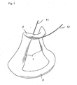
- Figure 1 is a schematic perspective view of a coil formed from a self-bonding insulated wire by winding, bonding and press molding;
- Figure 2 is a schematic front elevational view of the coil which is used for indicating its dimensions including its neck diameter;
- Figure 3 is a schematic view of the coil which is used for explaining a method of determining its distortion; and
- Figures 4(a) and 4(b) are schematic views of the coil which are used for explaining a method of measuring the bonding strength bearing on its end at which its winding was started.
- The invention will now be described more specifically by way of examples embodying it, as well as comparative examples representing the prior art. It is, however, to be understood that these examples are merely illustrative, and are not intended for limiting the scope of this invention. In the following description, "%" and "parts" are on a weight basis unless otherwise noted.
- A bonding varnish having a resin content of 18% was prepared by dissolving 100 parts of X7079 of Daicel-Hüls Ltd. having a melting point of 130°C as a copolyamide resin and 5 parts of A-100 of Unitica, which was nylon 66 having a melting point of 260°C, as a high-melting nylon resin, in a mixed solvent consisting of cresol and xylene in a weight ratio of 70:30. The varnish was applied onto an insulated polyesterimide wire having a conductor diameter of 0.250 mm and a final outside diameter of 0.290 mm, and baked in an enameling oven having a length of 3 m and a temperature of 300°C, while the wire was fed therethrough at a speed of 36 m/min. Its application and baking were repeated three times to form a bonding layer having a thickness of 0.010 mm on the wire, and thereby make a self-bonding insulated wire embodying this invention.
- A self-bonding insulated wire embodying this invention was made by employing 2 parts of nylon 66, and otherwise repeating Example 1.
- A self-bonding insulated wire embodying this invention was made by employing 9 parts of nylon 66, and otherwise repeating Example 1.
- A self-bonding insulated wire embodying this invention was made by employing 5 parts of F5000 of Unitica, which was nylon 46 having a melting point of 290°C, as the high-melting nylon resin, and otherwise repeating Example 1.
- A self-bonding insulated wire embodying this invention was made by employing 5 parts of A1030JR of Unitica, which was
nylon 6 having a melting point of 210°C, as the high-melting nylon resin, and otherwise repeating Example 1. - A bonding varnish having a resin content of 18% was prepared by dissolving X7079 of Daicel-Hüls Ltd. having a melting point of 130°C as the copolyamide resin in a mixed solvent consisting of cresol and xylene in a weight ratio of 70:30. A self-bonding insulated wire representing the prior art was made by employing the varnish and otherwise repeating Example 1.
- A self-bonding insulated wire representing the prior art was made by employing 15 parts of A-100 of Unitica as the high-melting nylon resin, and otherwise repeating Example 1.
- A self-bonding insulated wire representing the prior art was made by employing PKHH, an epoxy resin of Union Carbide, instead of the copolyamide resin, and otherwise repeating Comparative Example 1.
- A self-bonding insulated wire representing the prior art was made by employing 5 parts of L1500 of Daicel-Hüls Ltd.,
nylon 12 having a melting point of 180°C, as the high-melting nylon resin, and otherwise repeating Example 1. - A self-bonding insulated wire representing the prior art was made by employing 20 parts of
nylon 12, and otherwise repeating Comparative Example 4. - Figure 1 shows a schematic perspective view of a coil formed from a self-bonding insulated wire by winding, bonding and press-molding.
Reference numeral 1 relates to the winding,reference numeral 2 relates to the upper flange andreference numeral 3 relates to the lower flange. The end portion of wire at which its winding was started has thereference numeral 11, and the end portion of wire at which its winding was finished is indicated with thereference numeral 12. - In figure 2, a schematic front elevational view of the coil is shown, wherein its dimensions are indicated.
Upper flange 2 has an upper flange diameter du. Aneck 6 of winding 1 has a neck diameter dn.Lower flange 3 has a lower flange diameter dl. The coil has a height h. In figure 3 a schematic view of the coil is shown for explaining a method of determining its distortion. With reference to ahorizontal plane 4 the amount of twist atwist is shown. In figures 4 (a) and 4 (b) schematic views of the coil are shown for explaining a method of measuring the bonding strength bearing on its end at which its winding was started. More specifically, figure 4 (a) shows the end ofwire 11, at which its winding was started, and the end ofwire 12, at which its winding was finished. In figure 4 (b) the end ofwire 11, at which its winding was started, is shown and a tension gauge is givenreference numeral 5. - Each of the wires made as described in Examples 1 to 5 and Comparative Examples 1 to 5 was used to form a coil shaped as shown in Figures 1 and 2, and having an upper flange diameter of 51 mm, a lower flange diameter of 122 mm, a height of 70 mm and a neck diameter of 40.5 to 41.0 mm. Three winding bobbins were installed in a winding machine. A deflection coil was made by winding each wire having a diameter of 0.25 mm by 220 turns, melting its bonding layer and press molding it in the winding machine set for operation with three seconds of application of an electric current at a voltage of 190 V, 15 seconds of pressing for cooling, and a die temperature of 40°C. The coil removed from the die was left to stand at room temperature for 24 hours, and its neck diameter, the amount of its distortion and the bonding strength of the wire at its end at which its winding had been started were determined in the ways as shown in Figures 2 to 4(b). Then, the coil was left to stand in an oven having a constant temperature of 120°C for 24 hours, and after its removal to room temperature, it was checked for any change in its neck diameter. The results are shown in Table 1.

- As is obvious from Table 1, the coil of the wire according to Comparative Example 1 not containing any high-melting nylon resin in its bonding layer had a larger neck diameter as formed than that of the die, and a large amount of distortion, though the wire had a high bonding strength and the coil did not show any substantial deformation by heat. The coil of the wire according to Comparative Example 2 containing 15 parts of high-melting nylon resin in the bonding varnish was found loosened due to the low bonding strength of the wire, though it showed a satisfactorily small amount of deformation and distortion as formed, and also a satisfactorily small amount of heat deformation. The coil of the wire according to Comparative Example 3 as made by using an epoxy varnish as the bonding varnish was found loosened due to the lack of the wire in bonding strength, and also showed a large amount of heat deformation, though it showed a satisfactorily small amount of deformation and distortion as formed. The coil of the wire according to Comparative Example 4 as made by using a high-melting nylon resin having a melting point lower than 200°C showed some improvements in its neck diameter and distortion as formed, but it still failed to reach the target levels. The coil of the wire according to Comparative Example 5 was found loosened due to the lack of the wire in bonding strength despite the use of a larger amount of high-melting nylon resin having a melting point lower than 200°C. On the other hand, the coils formed from the self-bonding insulated wires according to Examples 1 to 5 of this invention were free from any appreciable loosening due to defective bonding, and were close in dimensions to the winding die after having been left to stand at room temperature, and also showed a high resistance to heat deformation at an elevated temperature of 120°C.
- A bonding varnish having a resin content of 18% was prepared by dissolving a polyamide resin A having a molar ratio of terminal carboxyl : amino groups of 20:80, a relative viscosity of 1.7 as determined in a 0.5% m-cresol solution thereof at 25°C and a melting point of 110°C as determined by DSC (Daiamid 470-1 of Daicel-Hüls Ltd.) in a mixed solvent consisting of cresol and xylene in a weight ratio of 70:30. The varnish was applied onto an insulated polyesterimide wire having a conductor diameter of 0.250 mm and a final outside diameter of 0.290 mm, and baked in an enameling oven having a length of 3 m and a temperature of 300°C, while the wire was fed therethrough at a speed of 36 m/min. Its application and baking were repeated three times to form a bonding layer having a thickness of 0.010 mm on the wire, and thereby make a self-bonding insulated wire embodying this invention.
- The molar ratio of the terminal carboxyl and amino groups in the polyamide resin was calculated from their concentrations which had been determined as described below. The concentration of the terminal amino groups was determined by dipping 0.1 to 0.5 g of a sample in 50 ml of a mixed solvent consisting of phenol and methanol in a volume ratio of 10:1, leaving it to stand for 12 hours, stirring it for several hours to dissolve it at room temperature, and subjecting the sample solution to automatic titration for reacting it with a 0. 01N methanol solution of HCl to determine the concentration of the NH2 groups in the sample solution. The concentration of the terminal carboxyl groups was determined by preparing a sample solution in the same way as described above, and subjecting it to automatic titration for reacting it with a 0.01N methanol solution of NaOH.
- A self-bonding insulated wire embodying this invention was made by employing an enameling oven temperature of 330°C and otherwise repeating Example 6.
- A self-bonding insulated wire embodying this invention was made by employing an enameling oven temperature of 360°C and otherwise repeating Example 6.
- A self-bonding insulated wire embodying this invention was made by employing a polyamide resin B having a molar ratio of terminal carboxyl : amino groups of 20:80, a relative viscosity of 1.7 as determined in a 0.5% m-cresol solution thereof at 25°C and a melting point of 125°C as determined by DSC (M-1422-1 of NIHON RILSAN K.K..) and otherwise repeating Example 6.
- A self-bonding insulated wire embodying this invention was made by employing the polyamide resin B as described above and otherwise repeating Example 7.
- A self-bonding insulated wire embodying this invention was made by employing the polyamide resin B as described above and otherwise repeating Example 8.
- A self-bonding insulated wire representing the prior art was made by employing a polyamide resin C having a molar ratio of terminal carboxyl : amino groups of 80:20, a relative viscosity of 1.7 as determined in a 0.5% m-cresol solution thereof at 25°C and a melting point of 110°C as determined by DSC (Daiamid 470-2 of Daicel-Hüls Ltd.) and otherwise repeating Example 6.
- A self-bonding insulated wire representing the prior art was made by employing the polyamide resin C as described above and otherwise repeating Example 7.
- A self-bonding insulated wire representing the prior art was made by employing the polyamide resin C as described above and otherwise repeating Example 8.
- A self-bonding insulated wire representing the prior art was made by employing a polyamide resin D having a molar ratio of terminal carboxyl : amino groups of 80:20, a relative viscosity of 1.7 as determined in a 0.5% m-cresol solution thereof at 25°C and a melting point of 125°C as determined by DSC (M-1442-2 of NIHON RILSAN K.K..) and otherwise repeating Example 9.
- A self-bonding insulated wire representing the prior art was made by employing the polyamide resin D as described above and otherwise repeating Example 10.
- A self-bonding insulated wire representing the prior art was made by employing the polyamide resin D as described above and otherwise repeating Example 11.
- A self-bonding insulated wire representing the prior art was made by employing a polyamide resin E having a molar ratio of terminal carboxyl : amino groups of 20:80, a relative viscosity of 1.3 as determined in a 0.5% m-cresol solution thereof at 25°C and a melting point of 110°C as determined by DSC (Daiamid 431 of Daicel-Hüls Ltd.) and otherwise repeating Example 6.
- Each of the wires made as described in Examples 6 to 11 and Comparative Examples 6 to 12 was used to form a coil shaped as shown in Figures 1 and 2, and having an upper flange diameter of 51 mm, a lower flange diameter of 122 mm, a height of 70 mm and a neck diameter of 40.5 to 41.0 mm. Three winding bobbins were installed in a winding machine. A deflection coil was made by winding each wire having a diameter of 0.25 mm by 220 turns, melting its bonding layer and press molding it in the winding machine set for operation with three seconds of application of an electric current at a voltage of 190 V, 15 seconds of pressing for cooling, and a die temperature of 40°C. The coil removed from the die was left to stand at room temperature for 24 hours, and its neck diameter, the amount of its distortion and the bonding strength of the wire at its end at which its winding had been started were determined in the ways as shown in Figures 2 to 4 (b). Then, each coil was left to stand in an oven having a constant temperature of 110°C, 120°C or 130°C for 24 hours, and after its removal to room temperature, it was checked for any change in its neck diameter. The results are shown in Table 2.

- As is obvious from Table 2, the coils of the wires according to Comparative Examples 6 to 8 and 9 to 11 each having a bonding layer formed from a polyamide resin varnish containing a lower molar ratio of terminal amino groups showed a worse degree of heat deformation with a rise in enameling oven temperature. A large increase in neck diameter was found in the coil of the wire according to Comparative Example 12 as made by employing a polyamide resin varnish having a low relative viscosity. On the other hand, the coils of the wires according to Examples 6 to 11 each having a bonding layer formed from a polyamide resin varnish having a higher molar ratio of terminal amino groups and an adequate relative viscosity did not show any substantial change in neck diameter, nor did they show any appreciable change in their good resistance to heat deformation irrespective of the enameling oven temperature varied in the range of 300°C to 360°C.
- A self-bonding insulated wire embodying this invention was made by employing 100 parts of polyamide resin B and 5 parts of A-100 of Unitica, nylon 66 having a melting point of 260°C, as a high-melting nylon resin to prepare a bonding varnish and otherwise repeating Example 9.
- A self-bonding insulated wire embodying this invention was made by employing an enameling oven temperature of 330°C and otherwise repeating Example 12.
- A self-bonding insulated wire embodying this invention was made by employing an enameling oven temperature of 360°C and otherwise repeating Example 12.
- A self-bonding insulated wire embodying this invention was made by employing 100 parts of polyamide resin D and 5 parts of A-100 of Unitica, nylon 66 having a melting point of 260°C, as a high-melting nylon resin to prepare a bonding varnish and otherwise repeating Comparative Example 9.
- A self-bonding insulated wire embodying this invention was made by employing an enameling oven temperature of 330°C and otherwise repeating Example 15.
- A self-bonding insulated wire embodying this invention was made by employing an enameling oven temperature of 360°C and otherwise repeating Example 15.
- Each of the wires made as described in Examples 12 to 17 was used to form a coil shaped as shown in Figures 1 and 2, and having an upper flange diameter of 51 mm, a lower flange diameter of 122 mm, a height of 70 mm and a neck diameter of 40.5 to 41.0 mm. Three winding bobbins were installed in a winding machine. A deflection coil was made by winding each wire having a diameter of 0.25 mm by 220 turns, melting its bonding layer and press molding it in the winding machine set for operation with three seconds of application of an electric current at a voltage of 190 V, 15 seconds of pressing for cooling, and a die temperature of 40°C. The coil removed from the die was left to stand at room temperature for 24 hours, and its neck diameter, the amount of its distortion and the bonding strength of the wire at its end at which its winding had been started were determined in the ways as shown in Figures 2 to 4(b). Then, each coil was left to stand in an oven having a constant temperature of 110°C, 120°C or 130°C for 24 hours, and after its removal to room temperature, it was checked for any change in its neck diameter. The results are shown in Table 3.

- As is obvious from Table 3, the coils of the wires each having a bonding layer formed from the varnish prepared by adding a high-melting nylon resin to a polyamide resin having a higher molar ratio of terminal amino groups and an appropriate relative viscosity (Examples 12 to 14) showed a still smaller change in neck diameter and a still better resistance to heat deformation than the coils of the wires having their bonding layers formed from varnishs not containing any high-melting nylon resin. The polyamide resin employed in Examples 15 to 17 had a lower molar ratio of terminal amino groups, but the addition of a high-melting nylon resin made it possible to form a satisfactory bonding layer on each of the wires according to Examples 15 to 17. The coils of those wires showed a smaller change in neck diameter and a better resistance to heat deformation than the coils of wires having their bonding layers formed from varnishes not containing any high-melting nylon resin.
Claims (6)
- A self-bonding insulated wire having a bonding outermost layer formed from a resin composition comprising 100 parts by weight of a copolyamide resin having a melting point of 105°C to 150°C, or a mixture of two or more such resins, and at least two, but less than 10 parts by weight of a high-melting nylon resin having a melting point of 200°C to 300°C.
- A self-bonding insulated wire as set forth in claim 1, wherein said high-melting nylon resin is a nylon resin having a melting point of at least 230°C.
- A self-bonding insulated wire as set forth in claim 1, wherein said high-melting nylon resin is nylon 66.
- A self-bonding insulated wire as set forth in claim 1, wherein said high-melting nylon resin is nylon 46.
- A self-bonding insulated wire as set forth in any of claims 1 to 4, wherein said copolyamide resin is a polyamide resin containing a lower molar ratio of terminal carboxyl groups than terminal amino groups.
- A self-bonding insulated wire as set forth in claim 5, wherein said ratio of said carboxyl : amino groups is from 20:80 to 0:100.
Applications Claiming Priority (7)
| Application Number | Priority Date | Filing Date | Title |
|---|---|---|---|
| JP311962/96 | 1996-11-22 | ||
| JP31196296A JP3903504B2 (en) | 1996-11-22 | 1996-11-22 | Self-bonding insulated wire |
| JP31196296 | 1996-11-22 | ||
| JP322688/96 | 1996-12-03 | ||
| JP32268896 | 1996-12-03 | ||
| JP32268896A JPH10162653A (en) | 1996-12-03 | 1996-12-03 | Self-fusing insulated wire |
| PCT/JP1997/003865 WO1998022955A1 (en) | 1996-11-22 | 1997-10-23 | Self-fusible insulated wire |
Publications (3)
| Publication Number | Publication Date |
|---|---|
| EP0881646A1 EP0881646A1 (en) | 1998-12-02 |
| EP0881646A4 EP0881646A4 (en) | 2002-06-12 |
| EP0881646B1 true EP0881646B1 (en) | 2005-09-21 |
Family
ID=26566968
Family Applications (1)
| Application Number | Title | Priority Date | Filing Date |
|---|---|---|---|
| EP97909622A Expired - Lifetime EP0881646B1 (en) | 1996-11-22 | 1997-10-23 | Self-fusible insulated wire |
Country Status (7)
| Country | Link |
|---|---|
| US (1) | US6231979B1 (en) |
| EP (1) | EP0881646B1 (en) |
| KR (1) | KR19990077131A (en) |
| DE (1) | DE69734235T2 (en) |
| MY (1) | MY124125A (en) |
| TW (1) | TW355794B (en) |
| WO (1) | WO1998022955A1 (en) |
Families Citing this family (8)
| Publication number | Priority date | Publication date | Assignee | Title |
|---|---|---|---|---|
| FR2760123B1 (en) * | 1997-02-24 | 1999-04-16 | Alsthom Cge Alcatel | ENAMELLED THREAD OF HIGH RESISTANCE TO PARTIAL DISCHARGES |
| JP3580725B2 (en) * | 1999-04-30 | 2004-10-27 | Ykk株式会社 | Method for manufacturing waterproof slide fastener |
| US6444916B2 (en) * | 2000-03-31 | 2002-09-03 | Kaneka Corporation | Self-bonding insulated wire and self-bonding litz wire comprising the same |
| US8193896B2 (en) * | 2008-08-15 | 2012-06-05 | Martin Weinberg | Polyamide electrical insulation for use in liquid filled transformers |
| CN101998785A (en) * | 2009-08-26 | 2011-03-30 | 深圳富泰宏精密工业有限公司 | Housing of electronic device and manufacturing method thereof |
| JP5454297B2 (en) * | 2010-03-30 | 2014-03-26 | 日立金属株式会社 | Insulated wire |
| US9728323B2 (en) | 2010-08-19 | 2017-08-08 | Martin Weinberg | Polyamide electrical insulation for use in liquid filled transformers |
| WO2016068101A1 (en) * | 2014-10-27 | 2016-05-06 | 宇部興産株式会社 | Polyamide composition and molding obtained therefrom |
Family Cites Families (7)
| Publication number | Priority date | Publication date | Assignee | Title |
|---|---|---|---|---|
| JPS50158886A (en) | 1974-06-14 | 1975-12-23 | ||
| JPS5136869B2 (en) * | 1974-10-25 | 1976-10-12 | ||
| JPS53106486A (en) * | 1977-02-28 | 1978-09-16 | Sumitomo Electric Ind Ltd | Self-fused insulating wire and coil obtained from it |
| US4420536A (en) * | 1981-11-23 | 1983-12-13 | Essex Group, Inc. | Self-bonding magnet wire |
| US5202187A (en) * | 1990-04-12 | 1993-04-13 | E. I. Du Pont De Nemours And Company | Coated wire |
| US5296556A (en) * | 1990-10-30 | 1994-03-22 | Union Camp Corporation | Three-component curable resin compositions |
| JP3367583B2 (en) * | 1995-03-10 | 2003-01-14 | 東京特殊電線株式会社 | Self-fusing magnet wire |
-
1997
- 1997-10-23 US US09/101,773 patent/US6231979B1/en not_active Expired - Fee Related
- 1997-10-23 EP EP97909622A patent/EP0881646B1/en not_active Expired - Lifetime
- 1997-10-23 DE DE69734235T patent/DE69734235T2/en not_active Expired - Fee Related
- 1997-10-23 WO PCT/JP1997/003865 patent/WO1998022955A1/en not_active Ceased
- 1997-10-23 KR KR1019980705268A patent/KR19990077131A/en not_active Ceased
- 1997-10-27 TW TW086115888A patent/TW355794B/en active
- 1997-11-21 MY MYPI97005612A patent/MY124125A/en unknown
Also Published As
| Publication number | Publication date |
|---|---|
| US6231979B1 (en) | 2001-05-15 |
| DE69734235D1 (en) | 2005-10-27 |
| TW355794B (en) | 1999-04-11 |
| EP0881646A4 (en) | 2002-06-12 |
| MY124125A (en) | 2006-06-30 |
| EP0881646A1 (en) | 1998-12-02 |
| WO1998022955A1 (en) | 1998-05-28 |
| DE69734235T2 (en) | 2006-07-06 |
| KR19990077131A (en) | 1999-10-25 |
Similar Documents
| Publication | Publication Date | Title |
|---|---|---|
| US6231979B1 (en) | Self-fusible insulated wire | |
| US4163826A (en) | Self-bonding magnet wires and coils made therefrom | |
| KR870000348B1 (en) | Insulated wire | |
| US6444916B2 (en) | Self-bonding insulated wire and self-bonding litz wire comprising the same | |
| US5219658A (en) | Self-bonding insulated wire and coils formed therefrom | |
| JP3903504B2 (en) | Self-bonding insulated wire | |
| JPH11306865A (en) | Self-fusing insulated wire | |
| JP3487340B2 (en) | Self-fusing wire, multi-core self-fusing wire, and deflection yoke coil using these | |
| US20060009581A1 (en) | Self-bonding insulated wire | |
| JP2002008453A (en) | Self-fusing insulated wire and self-fusing litz wire using it | |
| KR100335341B1 (en) | Self-bonding enamel wire and litz wire | |
| JP4761637B2 (en) | Self-bonding electrically insulating paint and self-bonding insulated wire using the same | |
| JPH02223107A (en) | Self-fusion insulated electric wire | |
| JP2582680B2 (en) | Solderable self-fusing polyesterimide insulated wire with an inner coating to prevent co-cracking | |
| JPH10162653A (en) | Self-fusing insulated wire | |
| JP4794719B2 (en) | Self-bonding insulated wire | |
| JPH08249936A (en) | Self-bonding magnet wire for alcohol winding or hot air winding | |
| JPS6366348B2 (en) | ||
| JP2003016847A (en) | Self-fusing insulated wire | |
| JP3114940B2 (en) | Self-fusing enameled wire | |
| JPH0766697B2 (en) | Heat resistant self-bonding enameled wire | |
| KR100303861B1 (en) | vanish composition | |
| JP3546472B2 (en) | Self-fusing enameled wire | |
| JPS62135569A (en) | Self-welding insulating paint and insulated wire | |
| JPH10172355A (en) | Insulated wire with surface lubricity |
Legal Events
| Date | Code | Title | Description |
|---|---|---|---|
| PUAI | Public reference made under article 153(3) epc to a published international application that has entered the european phase |
Free format text: ORIGINAL CODE: 0009012 |
|
| 17P | Request for examination filed |
Effective date: 19980812 |
|
| AK | Designated contracting states |
Kind code of ref document: A1 Designated state(s): DE FR GB NL |
|
| A4 | Supplementary search report drawn up and despatched |
Effective date: 20020503 |
|
| AK | Designated contracting states |
Kind code of ref document: A4 Designated state(s): DE FR GB NL |
|
| RIC1 | Information provided on ipc code assigned before grant |
Free format text: 7H 01B 7/02 A, 7H 01B 3/30 B, 7C 09D 177/06 B, 7C 09J 177/06 B, 7C 08L 77/06 B, 7H 01F 5/06 B, 7H 01J 29/76 B, 7C 09D 177/00 B |
|
| 17Q | First examination report despatched |
Effective date: 20040405 |
|
| GRAP | Despatch of communication of intention to grant a patent |
Free format text: ORIGINAL CODE: EPIDOSNIGR1 |
|
| GRAS | Grant fee paid |
Free format text: ORIGINAL CODE: EPIDOSNIGR3 |
|
| RIN1 | Information on inventor provided before grant (corrected) |
Inventor name: TAMURA, KAZUSHIGE Inventor name: UKAWA, TAKESHI Inventor name: NISHIDA, SHIGEO Inventor name: NAGAMINE, SEIICHI |
|
| GRAA | (expected) grant |
Free format text: ORIGINAL CODE: 0009210 |
|
| RAP1 | Party data changed (applicant data changed or rights of an application transferred) |
Owner name: KANEKA CORPORATION |
|
| AK | Designated contracting states |
Kind code of ref document: B1 Designated state(s): DE FR GB NL |
|
| REG | Reference to a national code |
Ref country code: GB Ref legal event code: FG4D |
|
| RIN1 | Information on inventor provided before grant (corrected) |
Inventor name: TAMURA, KAZUSHIGE Inventor name: UKAWA, TAKESHI Inventor name: NISHITA, SHIGEO Inventor name: NAGAMINE, SEIICHI |
|
| REF | Corresponds to: |
Ref document number: 69734235 Country of ref document: DE Date of ref document: 20051027 Kind code of ref document: P |
|
| ET | Fr: translation filed | ||
| PLBE | No opposition filed within time limit |
Free format text: ORIGINAL CODE: 0009261 |
|
| STAA | Information on the status of an ep patent application or granted ep patent |
Free format text: STATUS: NO OPPOSITION FILED WITHIN TIME LIMIT |
|
| 26N | No opposition filed |
Effective date: 20060622 |
|
| PGFP | Annual fee paid to national office [announced via postgrant information from national office to epo] |
Ref country code: NL Payment date: 20061015 Year of fee payment: 10 |
|
| PGFP | Annual fee paid to national office [announced via postgrant information from national office to epo] |
Ref country code: GB Payment date: 20061018 Year of fee payment: 10 |
|
| PGFP | Annual fee paid to national office [announced via postgrant information from national office to epo] |
Ref country code: DE Payment date: 20061019 Year of fee payment: 10 |
|
| GBPC | Gb: european patent ceased through non-payment of renewal fee |
Effective date: 20071023 |
|
| NLV4 | Nl: lapsed or anulled due to non-payment of the annual fee |
Effective date: 20080501 |
|
| PG25 | Lapsed in a contracting state [announced via postgrant information from national office to epo] |
Ref country code: DE Free format text: LAPSE BECAUSE OF NON-PAYMENT OF DUE FEES Effective date: 20080501 |
|
| REG | Reference to a national code |
Ref country code: FR Ref legal event code: ST Effective date: 20080630 |
|
| PG25 | Lapsed in a contracting state [announced via postgrant information from national office to epo] |
Ref country code: NL Free format text: LAPSE BECAUSE OF NON-PAYMENT OF DUE FEES Effective date: 20080501 |
|
| PGFP | Annual fee paid to national office [announced via postgrant information from national office to epo] |
Ref country code: FR Payment date: 20061010 Year of fee payment: 10 |
|
| PG25 | Lapsed in a contracting state [announced via postgrant information from national office to epo] |
Ref country code: GB Free format text: LAPSE BECAUSE OF NON-PAYMENT OF DUE FEES Effective date: 20071023 |
|
| PG25 | Lapsed in a contracting state [announced via postgrant information from national office to epo] |
Ref country code: FR Free format text: LAPSE BECAUSE OF NON-PAYMENT OF DUE FEES Effective date: 20071031 |