EP0881076A1 - Ink key control system in a printing press - Google Patents
Ink key control system in a printing press Download PDFInfo
- Publication number
- EP0881076A1 EP0881076A1 EP98301254A EP98301254A EP0881076A1 EP 0881076 A1 EP0881076 A1 EP 0881076A1 EP 98301254 A EP98301254 A EP 98301254A EP 98301254 A EP98301254 A EP 98301254A EP 0881076 A1 EP0881076 A1 EP 0881076A1
- Authority
- EP
- European Patent Office
- Prior art keywords
- ink
- film thickness
- matrix
- plate
- equation
- Prior art date
- Legal status (The legal status is an assumption and is not a legal conclusion. Google has not performed a legal analysis and makes no representation as to the accuracy of the status listed.)
- Granted
Links
- 238000007639 printing Methods 0.000 title claims description 38
- 238000000034 method Methods 0.000 claims abstract description 76
- 238000005315 distribution function Methods 0.000 claims abstract description 32
- 239000011159 matrix material Substances 0.000 claims description 72
- 239000000758 substrate Substances 0.000 claims description 35
- 230000003287 optical effect Effects 0.000 claims description 25
- 238000000354 decomposition reaction Methods 0.000 claims description 3
- 230000000694 effects Effects 0.000 abstract description 26
- 238000012937 correction Methods 0.000 abstract description 11
- 238000007645 offset printing Methods 0.000 abstract description 7
- 230000001419 dependent effect Effects 0.000 abstract description 4
- 239000000976 ink Substances 0.000 description 482
- 239000013598 vector Substances 0.000 description 34
- 230000008859 change Effects 0.000 description 18
- 238000005259 measurement Methods 0.000 description 17
- 239000007787 solid Substances 0.000 description 14
- 238000012360 testing method Methods 0.000 description 10
- 238000013461 design Methods 0.000 description 8
- 238000013459 approach Methods 0.000 description 5
- 239000003086 colorant Substances 0.000 description 5
- 238000001739 density measurement Methods 0.000 description 5
- 230000008569 process Effects 0.000 description 5
- 239000002184 metal Substances 0.000 description 4
- 238000012544 monitoring process Methods 0.000 description 4
- 238000012545 processing Methods 0.000 description 4
- 238000012546 transfer Methods 0.000 description 4
- 238000006243 chemical reaction Methods 0.000 description 3
- 238000005094 computer simulation Methods 0.000 description 3
- 239000000463 material Substances 0.000 description 3
- 238000012935 Averaging Methods 0.000 description 2
- 238000004364 calculation method Methods 0.000 description 2
- 239000010432 diamond Substances 0.000 description 2
- 238000005461 lubrication Methods 0.000 description 2
- 230000001151 other effect Effects 0.000 description 2
- 239000000049 pigment Substances 0.000 description 2
- 230000035945 sensitivity Effects 0.000 description 2
- 230000000007 visual effect Effects 0.000 description 2
- 238000011179 visual inspection Methods 0.000 description 2
- 230000003321 amplification Effects 0.000 description 1
- 238000004458 analytical method Methods 0.000 description 1
- 230000008901 benefit Effects 0.000 description 1
- 238000004422 calculation algorithm Methods 0.000 description 1
- 230000002301 combined effect Effects 0.000 description 1
- 238000010276 construction Methods 0.000 description 1
- 230000003247 decreasing effect Effects 0.000 description 1
- 230000001934 delay Effects 0.000 description 1
- 238000010586 diagram Methods 0.000 description 1
- 229910003460 diamond Inorganic materials 0.000 description 1
- 238000006073 displacement reaction Methods 0.000 description 1
- 238000005516 engineering process Methods 0.000 description 1
- 238000002474 experimental method Methods 0.000 description 1
- 239000012530 fluid Substances 0.000 description 1
- 238000012986 modification Methods 0.000 description 1
- 230000004048 modification Effects 0.000 description 1
- 238000003199 nucleic acid amplification method Methods 0.000 description 1
- 238000000424 optical density measurement Methods 0.000 description 1
- 238000003908 quality control method Methods 0.000 description 1
- 230000004044 response Effects 0.000 description 1
- 230000006641 stabilisation Effects 0.000 description 1
- 238000011105 stabilization Methods 0.000 description 1
- 235000019640 taste Nutrition 0.000 description 1
- 230000007704 transition Effects 0.000 description 1
- 239000002699 waste material Substances 0.000 description 1
Images


Classifications
-
- B—PERFORMING OPERATIONS; TRANSPORTING
- B41—PRINTING; LINING MACHINES; TYPEWRITERS; STAMPS
- B41F—PRINTING MACHINES OR PRESSES
- B41F31/00—Inking arrangements or devices
- B41F31/02—Ducts, containers, supply or metering devices
- B41F31/04—Ducts, containers, supply or metering devices with duct-blades or like metering devices
- B41F31/045—Remote control of the duct keys
-
- B—PERFORMING OPERATIONS; TRANSPORTING
- B41—PRINTING; LINING MACHINES; TYPEWRITERS; STAMPS
- B41F—PRINTING MACHINES OR PRESSES
- B41F31/00—Inking arrangements or devices
Definitions
- the present invention relates generally to a system and method for controlling the ink feed in a web-offset printing press in order to achieve and maintain target values of color. More particularly, the invention relates to a system for controlling the ink feed and compensating for the lateral ink flow due to the movement of the vibrator rollers, the ink back-flow to the ink reservoir, the nonlinear relationship between ink thickness and ink density, and the inverse relationship between the plate coverage and the time constant required for achieving acceptable color quality.
- a web-offset printing press includes an inking assembly for each color of ink used in the printing process.
- Each inking assembly includes an ink reservoir as well as a blade disposed along the outer surface of an ink fountain roller.
- the amount of ink supplied to the roller train of the press and ultimately to a substrate such as paper is adjusted by changing the spacing between the edge of the blade and the outer surface of the ink fountain roller.
- the blade is divided into a plurality of blade segments, and the position of each blade segment relative to the ink fountain roller is independently adjustable by movement of an adjusting screw, or ink key, to thereby control the amount of ink fed to a corresponding vertical strip or zone of the substrate.
- electronic equivalents of an ink key also exist, such as the equivalent disclosed in U.S. Pat. No. 5,129,320, issued July 14, 1992 to Fadner.
- the term "ink key" is intended to include any device which controls the amount of ink fed to a corresponding vertical strip or zone of the substrate.
- ink is also spread laterally from one vertical zone to adjacent vertical zones due to the movement of vibrator rollers, which oscillate in a lateral direction relative to the substrate.
- the amount of ink on the ink fountain roller itself is also adjustable by changing the angle that the ink fountain roller rotates each stroke. Typically, this occurs by adjusting a ratchet assembly, as is known in the art.
- ink keys In order to preset the initial positions of the ink keys, it is common for a printing press operator to examine printed copies or proofs of the image to be printed and to note the amount of color necessary in respective vertical zones of the image to be printed. Based on this visual examination as well as experience with the press, ink, and type of substrate (typically paper), the operator will preset the ink keys to approximate the settings that will be required once the press is running.
- low-tack yellow ink has a low pigment strength and requires a greater amount of ink to produce an image with a given optical density.
- uncoated paper requires more ink than does coated paper to achieve an image having a given optical density.
- the press operator In addition to presetting the ink keys, once the press is running, it is common for a press operator to continually monitor the printed output and to make appropriate ink key adjustments in order to achieve appropriate quality control of the color of the printed image. For example, if the color in a zone is too weak, the operator adjusts the corresponding ink key to allow more ink flow to that zone; if the color is too strong, the corresponding ink key is adjusted to decrease the ink flow. During operation of the printing press, further color adjustments may be necessary to compensate for changing press conditions, or to account for the personal preferences of the customer.
- Plate coverage is the ratio of the inked area to the total plate area, and provides a measure of the amount of ink required to print the desired image.
- U.S. Pat. No. 3,958,509 describes a method wherein the plate coverage of each ink key zone is determined by photo-electronic scanning of a portion of the printing plate. The ink key positions are calculated to be proportional to the plate coverage in a corresponding zone.
- U.S. Pat. Nos. 4,210,818, 4,187,435, and 4,180,741 also describe systems wherein ink keys are adjusted according to the plate coverage in a corresponding zone.
- the plate coverage is determined using a light source to illuminate an image area such as a photographic film of the image or a printing plate to be printed and using light sensors to measure the light reflected from the film.
- the ink key positions are calculated to be proportional to the plate coverage in a corresponding zone.
- Recent computer-to-plate technology has enabled the digital representation of an image to be directly transferred to a printing plate. Use of this digital pre-press data will also permit plate coverage to be easily and more accurately obtained.
- a web-offset printing system 10 for printing a multi-color image upon a web 12 is illustrated.
- four printing units 14, 16, 18, and 20 each print one color of the image upon the web 12. This type of printing is commonly referred to as web-offset printing.
- Each printing unit 14, 16, 18, 20 includes an upper blanket cylinder 22, an upper printing plate cylinder 24, a lower blanket cylinder 26, and a lower printing plate cylinder 28 to permit printing on both sides of web 12.
- colors 31, 32, 33, and 34 on units 14, 16, 18, and 20 respectively are typically black (K), cyan (C), magenta (M), and yellow (Y).
- K black
- C cyan
- M magenta
- Y yellow
- the location of printing units 14, 16, 18, and 20 relative to each other is determined by the printer, and may vary.
- Each printing unit 14, 16, 18, and 20 includes an associated inking assembly 36 as shown in Fig. 2.
- Inking assembly 36 operates to supply ink to the web 12 in order to print images.
- Inking assembly 36 includes an ink reservoir 38 disposed adjacent an ink fountain roller 40 (also known as the ink ball) which extends laterally across the web.
- a blade 42 extends along the ink fountain roller 40 and is segmented so that the spacing of each segment relative to the ink fountain roller 40 can be independently adjusted.
- each blade segment 44 has an edge 46 which is moved toward and away from the outer surface 48 of the ink fountain roller 40 by adjustment of an associated ink flow adjustment device 50.
- a portion of the ink fountain roller 40 forms one main wall of the ink reservoir 38.
- the other principal wall of the reservoir 38 is provided by the blade segments 44.
- Ink passes from the ink reservoir 38 through the space between the surface of the ink fountain roller 40 and the lower edge 46 of the blade segment 44, and the spacing of the blade edge 46 to the ink fountain roller 40 acts to control the thickness of the ink film provided to the outer surface 48 of ink fountain roller 40.
- a plurality of the ink flow adjustment devices 50 are disposed at equally-spaced lateral locations along the inking assembly 36 to press against the blade segments 44 at those locations to establish and adjust the size of the space between the roller 40 and the blade segment 44.
- Each ink flow adjustment device 50 includes an ink key 54 having screw threads engaging threads in a fixed portion of the frame of the inking assembly 36.
- the ink key 54 has a tip portion 56 which pushes against the associated blade segment 44 to deflect it and to thereby provide locally adjustable control of the spacing and the ink feed.
- the ink key 54 is driven by a bi-directional actuator motor 58 which operates to move the ink key 54 toward and away from the ink fountain roller 40.
- a potentiometer 60 has a movable arm mechanically connected with the ink key 54.
- the potentiometer 60 has a pair of outside electrical terminals and an inside electrical terminal located between the outside electrical terminals.
- the inside terminal of the potentiometer is mechanically connected to the movable arm of the potentiometer 60.
- the position of the movable arm of the potentiometer 60 depends upon the position of the ink key 54.
- the potentiometer 60 is energized at its outside electrical terminals so that an electrical signal indicative of the position of the ink key is produced at the inside electrical terminal of the potentiometer.
- the inside terminal of the potentiometer is electrically connected to line 64.
- the electrical signal on line 64 is connected as an input signal to the control console and processing unit 68 as shown in Fig. 4.
- the motor 58 is responsive to a signal on line 66 to position the ink key 54 as required.
- Ink key control system 70 operates to set the position of the ink keys to control the position of blade segments 44 in order to control the amount of ink fed to corresponding ink key zones on the web 12.
- a control console and processing unit 68 receives data on line 72 from a pre-press data system 74.
- the data on line 72 provides information regarding the plate coverage of the desired image.
- optical plate scanners can be used to provide the data on line 72.
- optical plate scanners typically provide appropriate plate calibration, uniformity corrections, and geometrical corrections.
- the data on line 72 could also be in a digital format from a system such as a CREO digital computer-to-plate system (CTP).
- CTP digital computer-to-plate system
- the data on line 72 could be from a CTP file wherein the total image area is obtained simply by summing together the image areas.
- the data on line 72 from a CREO digital computer-to-plate system is typically an image in the conventional form of Tagged-Image-File-Format (TIFF) which represents the plate, typically in a 300 dot-per-inch format. This format provides far more resolution than is required for ink setting, and such large amounts of data are unwieldy.
- TIFF Tagged-Image-File-Format
- the software program Photoshop (Version 4.0) is used to convert the bit-mapped TIFF files created by the platesetter into gray level images of lower resolution, finally output as raw files, which will be read in by the coverage calculation program in Appendix 1.
- control console and processing unit 68 in response to the plate coverage data and an appropriate inking system model as more fully described below, generates signals on line 66 to drive motors 58 to independently control the position of each blade segment 44.
- control console and processing unit 68 sends a signal via line 76 to rotation control unit 78.
- Rotation control unit 78 operates via a ratchet assembly (not shown) to control the amount of rotation of the ink fountain roller 40 during each stroke, as is known in the art.
- An appropriate inking system model takes into account several different aspects of the inking system, from the ink reservoir 38 to the web 12.
- One aspect of the ink key control system 70 which is included in the model is the relationship between the actual ink key opening and the displayed ink key value at unit 68.
- signals on line 66 from unit 68 are sent to corresponding motors 58 which move the associated blade segments 44.
- the position of each blade segment 44 is measured by means of an associated potentiometer 60 and displayed as a value on an LED display 80. (See e.g., U.S. Pat. No. 4,008,664).
- the relationship between the actual ink key openings, for example, as measured with a feeler gauge, and the displayed ink key values at display 80 is shown in Fig. 5.
- FIG. 6(a)-6(c) Another aspect included in the inking system model is the relationship between the ink film thickness on the ink fountain roller and the ink key opening. This relationship is illustrated in Figs. 6(a)-6(c) for the ink colors cyan, magenta, and yellow.
- Ink film thickness on the ink fountain roller was measured using a laser displacement sensor such as an Omron Z4M-W40 instrument. This sensor uses a small laser spot less than 1 mm in diameter with triangulation to measure relative differences in height and has a resolution of 1.5 micron (.06 mil).
- the results for cyan, magenta, and yellow inks suggest a linear relationship between the ink film thickness on the ink fountain roller and the ink key openings, although with different slopes, z.
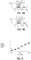
- Fig. 7 is an illustration of a side view of a roller train 96 of a lower printing unit of a Harris M1000B printing press.
- Ink is supplied from the inking assembly 36 via the ink fountain roller 40 to a ductor roller 98 which continuously moves back and forth from contact with the ink fountain roller 40 and roller 100.
- Ink is then supplied from roller 100 to the various other rollers 102-124. Because it is not feasible to measure the ink film thickness on the ductor roller 98, the assumption is made that the relationship between the ink film thickness on the ink fountain roller 40 and the ink film thickness on the ductor roller 98 is also linear.
- the rotation control unit 78 sets the ratchet setting to linearly control the angle that the ink fountain roller 40 rotates during each stroke.
- the rotation angle along with the positions of the blade segments 44, determine the amount of ink transferred to the ductor roller 98.
- the relationship between rotation angle and the amount of ink transferred to ductor roller 98 is also assumed to be linear.
- Another necessary aspect of the model is the relationship between the ink required at the ductor roller and the plate coverage (without considering the effect of the vibrator rollers).
- Various plate coverage equations can be used.
- a model-based plate coverage equation can be derived as described below.
- rollers 100, 104, 114, and 118 are vibrator rollers which also oscillate back and forth in a lateral direction with respect to the web 12, thereby operating to spread ink from one ink key zone to adjacent ink key zones.
- Outer surfaces S -1 , S 0 , S 1 ,...,S 28 of rollers 98-124 have associated ink film thicknesses t -1 , t 0 , t 1 , ..., t 28 .
- the ink film thickness on the web surface S 29 is designated as t 29 .
- the complete roller train 96 (from the ductor roller 98 to the web 12) is modelled based on the assumption of continuity of ink film thickness. Rollers 100 and 102 and associated surfaces S 1 -S 4 as well as ink film thicknesses t 1 -t 4 are shown in Fig. 8. Ink is transferred from roller 100 to roller 102.
- roller 100 is made of metal
- roller 102 is made of rubber.
- Equations similar to Equation 4 and Equation 5 are sufficient to describe the ink film thickness on each roller surface in the roller train 96, except for the ink film thickness on the plate cylinder, roller 122.
- the surface of the plate cylinder 122 includes a printing plate comprising the image to be printed.
- a different set of equations are applicable to the nip point between a form roller 106, 110, 120 and the plate cylinder 122. Although form rollers 106, 110, and 120 perform similar functions, roller 120 will be used in this example. Referring to Fig. 9, ink is transferred from the form roller 120 to the plate cylinder 122. For the areas of the plate cylinder 122 which have solid coverage, the nip equations remain the same as Equations 4 and 5.
- Equations 4-8 equations are formed for each nip point of the roller train 96 and the set of resulting simultaneous equations is solved for ink film thickness at each surface S -1 - S 29 .
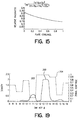
- Fig. 10 is essentially another way of displaying the data of Fig. 14, with the data normalized differently.
- Fig. 10 shows a series of curves depicting ink film thickness (in arbitrary units) at each surface S -1 - S 29 of the roller train 96. Each curve corresponds to a different value of plate coverage from 0% to 100%.
- Fig. 10 demonstrates that if the ink film thickness is desired to be 1 arbitrary unit on the web surface S 29 , then the ink film thickness fed to the roller 98 has to be approximately 3 to 7 units, depending on the plate coverage.
- Fig. 15 illustrates a plot of this equation, i.e., relative ink film thickness on paper versus plate coverage.
- the results of taking the reciprocal of t 29 and normalizing are shown by the data points indicated by diamonds in Fig. 11. This is the model-based plate coverage equation.
- the relationship between the diamond data points can be approximated by a straight line, line 180.
- Equation 10 indicates that an ink feed of 46% of that required for full coverage is needed even for 0% plate coverage. This contradicts the conventional paradigm that no ink is needed if there is 0% coverage.
- the conventional paradigm of how much ink feed is required for 0% coverage is illustrated as line 182 in Fig. 11. Line 182 is a proportional plate coverage equation. According to the conventional paradigm, the ink key should not be opened if the plate coverage is zero. However, the conventional paradigm is not accurate because it ignores the fact that the ink is not only being transferred forward to the web 12, but that part of the ink is also transferred back to the ink reservoir 38.
- the difference between the ink supplied to the ductor roller 98 and the ink returned to the reservoir 38 must equal the ink supplied to the web in order to take into account the total amount of ink.
- the ink key opening is directly related to the ink supply and not to the ink consumption. It should also be noted that in order to print uniformly across the web, the ink film thickness has to be maintained uniformly across the form rollers (which transfer ink to the printing plates), even if there is only a tiny dot to be printed in a certain ink key zone.
- Equation 10 was derived from data obtained on a Harris M1000B press; however, the same approach can be applied to any inking train arrangement.
- direct measurement can be made, for example, by utilizing a sequence of plates with progressively higher coverage.
- an empirically-based plate coverage equation can be determined by taking a series of measurements using plates having for example, three portions, each portion having a different percentage solid ink coverage. The portions should be wide enough so that the vibrator rollers do no influence the results. Also, the plate should have solid coverage so dot gain problems do not influence the results.
- the first plate is used to print images and measurements are taken at points in the middle of each portion. The press conditions should remain the same while another similar plate having different plate coverage percentage values is used to print images, and more measurements are taken.
- the sensitivity of E, the relative ink utilization factor, to changes in the split ratio, k was investigated by calculating corresponding lines for various values of the split ratio.
- k was set to .2, .5, and .8, corresponding to ink favoring metal rollers, rubber and metal rollers equally favoring ink, and ink favoring rubber rollers, respectively.
- the results are illustrated in Fig. 12 and demonstrate that the assumption of a fixed split ratio of .5 does not drastically affect the results of Fig. 11.
- the relationship between the optical density of an ink film and the ink film thickness on the web is another aspect of the inking system model.
- a first-order approximation of that relationship is that the optical density is proportional to ink film thickness on the web.
- the first-order approximation fails to account for the phenomena of saturation.
- the saturation density, D t depends most strongly upon the smoothness of the substrate. Uncoated paper will have a much lower saturation density than coated paper. Another factor which affects the saturation density is the particular ink used. For example, yellow ink has a lower saturation density than black ink.
- the constant m is the ink strength parameter, which depends largely upon the tinctorial strength of the ink, that is, the amount of pigment.
- Equation 11 is commonly known as the Tollenaar-Ernst formula.
- the ratchet assembly was set to various percentages, e.g. 10%, 20%, 30%,...,90%, a solid image was printed and its optical density measured.
- Tollenaar-Ernst formula was used to model the relationship between ink film thickness and density.
- One skilled in the art will be aware of other, similar equations, which empirically describe this relationship. For example, six different equations are provided in Chou, Shem, "Relationship Between Ink Mileage and Ink Transfer", in the 1991 TAGA Proceedings.
- Equations 10 and 12 The inking system model so far described by Equations 10 and 12 is best illustrated as shown in Fig. 17.
- the description of the model at this point is not complete because the effect of the lateral movement of the vibrator rollers on the ink flow has not been taken into account.
- the effect of the vibrator rollers on ink flow can be modelled using an ink key distribution function which is convolved with the ink key openings.
- a convolution model is one in which it is assumed that opening a given ink key will result in a fixed percentage of ink being transferred to each of the neighboring ink key zones.
- the convolution model further assumes that the percentage of ink deposited on a particular zone is independent of the magnitude of the ink key opening as well as independent of plate coverage.
- Fig. 17 therefore depicts a portion of the inking system model wherein the ink key openings convolved with an ink key distribution function (at block 186) provides information regarding the amount of ink supplied to the plate cylinder.
- the relative ink utilization factor, E which is a function of plate coverage in each ink key zone, is implemented at block 188, and provides information regarding the ink thickness required at the web.
- An ink saturation block 190 relates ink film thickness to density values.
- the form of the ink key distribution function was determined by conducting various tests on a Harris M1000B printing press using the printing plate test design of Fig. 18.
- the test design consists of a series of vertical strips, each of which corresponds to one ink key on the press.
- the width of each strip is four centimeters, which corresponds to the width of the blade segment 44 controlled by each ink key (i.e., the width of the associated ink key zone).
- the odd-numbered ink key strips in the test design have solid coverages which extend for varying lengths of the plate.
- the even-numbered ink key strips have varying halftone coverages which extend the full length of the plate.
- the test design thus includes two ink key zones for each step in coverage amount (i.e., 0%, 10%, 20%, ..., 100%).
- One ink key strip achieves a given plate coverage by solid coverage over a percentage of the plate length, and the other achieves the same plate coverage by a corresponding halftone percentage extending the full plate length.
- ink key #13 corresponds to a solid strip extending the length of the plate and which is sandwiched by a pair of 90% halftone strips.
- the optical densities of the corresponding ink key zones of the printed image were then measured.
- solid curve 200 in Fig. 19 the optical density of the solid strip was measured to be 2.1, and the densities for the neighboring halftone strips were approximately .15. This demonstrates that ink does not flow to the neighboring zones just because of the demand from zones of high coverage or because of roller pressure. Instead, ink is distributed to neighboring zones exclusively by the forceful motion of the vibrator rollers.
- the vibrator rollers have a lateral travel of roughly 1.5 inches.
- the ink distribution with the vibrator rollers enabled is illustrated as curve 202 of Fig. 19.
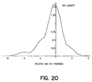
- Fig. 20 is a more detailed plot of curve 202 of Fig. 19.
- Solid ink density is plotted versus relative ink key position, with the zero point of the plot corresponding to the center of the ink key which was opened (key #13). Densities were measured every one centimeter in the printed image corresponding to the solid black bar at the bottom of the test design. It appears that curve 202 is stretched out with respect to curve 200 for at least two to three key zones on each side of the zone corresponding to ink key #13, due to the fact that there were four vibrator rollers in a Harris M1000B printing press.
- curve 202 is asymmetrical due to the coverage differences between zones.
- Curve 204 illustrates plate coverage plotted versus ink key number. After correcting curve 202 for differences in plate coverage, a more symmetrical ink spread curve is obtained, as more fully described below.
- the measured density data illustrated in Fig. 20 is corrected first for the effects of ink saturation, and then for plate coverage.
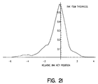
- Fig. 21 illustrates the results of applying Equation 13 (i.e., the inverse of the saturation ink formula) to the data of Fig. 20 to obtain a plot of ink film thickness versus ink key position (relative to ink key #13).
- Equation 10 takes into account the relative efficiency of each ink key zone's use of a given ink film thickness. Areas of very low plate coverage will use the ink which is spread by the vibrator rollers "more efficiently" than ink key zones having a higher plate coverage. A low coverage area will therefore require a relatively smaller ink key opening. Therefore, to calculate the required ink key setting to achieve a predetermined solid ink density, a multiplication by the relative ink utilization factor (which is dependent on plate coverage) is required.
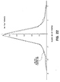
- the solid line in Fig. 22 shows the results of applying Equation 10 to the curve of Fig. 21 (or applying both Equation 10 and Equation 13 to the original data of Fig. 20).
- the dotted line in Fig. 22 represents a symmetrified version of the data, obtained by averaging corresponding points on either side of the peak.
- This dotted line represents the ink key distribution function 206.
- This is the spread of ink from a source of ink which is the width of an ink key zone. This is not a "point spread function" due to the ink spread from a single point of ink.
- the ink key distribution function 206 is the convolution of the true point spread function with a pulse function which is the width of an ink key zone.
- Vector V is obtained by averaging the data in Fig. 23 over the width corresponding to each ink key zone (four centimeters), and then scaling so that the addition of all vector elements adds up to 1.
- the elements in vector V can then be interpreted as the fraction of ink which is distributed to a specific ink key zone.
- Each ink key results in its own distribution of ink, which is proportional to the ink key opening.
- 46% of the ink provided by a given ink key is passed directly into its corresponding ink key zone, 20% is passed to the immediate neighboring zones, and 4% is passed to the next set of neighbors, and so on.
- Fig. 25 is an illustration of the complete inking system model.
- Another way to view the relationship between the ink film thickness on the ductor roller and the ink key distribution function is in terms of convolution, rather than the matrix multiplication of Equation 14.
- the inking system model represented in Fig. 25 can be used to calculate an expected ink optical density given the displayed ink key settings. In this case, calculations proceed from left to right.
- the inking system model can also be used to calculate required ink key settings given required densities and plate coverages, c, for each ink key zone, in which case, calculations proceed from right to left in Fig. 25.
- calculations proceed from right to left in Fig. 25.
- In order to determine the required ink key openings from data representing zonal plate coverage and required densities requires a deconvolution or matrix multiplication involving the inverted matrix VM, as further described below.
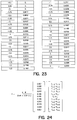
- a 24 by 24 element matrix, VM is formed as the vibrator matrix, where VM ij represents the portion of ink from ink key j which reaches the plate in ink key zone i.
- matrix VM is a Toeplitz matrix, that is, a matrix in which each row is a shifted version of the row above. Each row contains the elements of the vector V.
- Matrix VM is illustrated in Fig. 26.
- inverted matrix VM is invertible, a solution for ink key openings is obtainable because the ink key openings are linearly related to the ink film thickness on the ductor roller.
- inverted matrix VM may be slightly ill-conditioned. This means that the matrix may amplify noise.
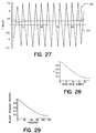
- Fig. 27 illustrates this effect.
- Line 212 is a plot of T when L is a vector of all ones.
- Line 214 is a plot of T when L is a vector with alternating ones and minus ones.
- Fig. 27 shows that the result obtained by multiplying matrix VM by a vector of all ones is not increased in magnitude, however, multiplying by a vector of alternating ones and minus ones results in a vector which is increased in magnitude by about 7.5. This presents a problem if noise happens to alternate between two values of equal magnitude, in which case the noise level will be magnified by a factor of 7.5.
- Singular value decomposition is a tool which can be used to lessen the noise amplification of straight matrix inversion.
- the SVD approach is to convert the matrix into one which is similar, but not as ill-conditioned as the original. This is accomplished by removing components of the matrix which cause the ill-conditioning, to create a new matrix.
- the inverse of the new matrix is called the pseudo-inverse.
- the value ⁇ is known as the eigenvalue.
- an N x N matrix will have N eigenvalues.
- Ax ⁇ x .
- Multiplication of an eigenvector x by a matrix A will scale that eigenvector by ⁇ . If noise is in the direction of one of the eigenvectors of VM -1 , then ⁇ predicts how much the noise will be amplified (or reduced).
- Fig. 28 illustrates the eigenvalues, plotted in descending order.
- the smallest eigenvalue is .134, which has a corresponding eigenvector which looks a lot like line 214 of Fig. 27.
- the largest etgenvalue is .982, which has a corresponding eigenvector like the line 212 in Fig. 27.
- Equation 17 Another approach to solving Equation 17 for T takes advantage of the convolution theorem.
- the convolution theorem states that convolution in the spatial domain is equivalent to multiplication in the frequency domain.
- Equation 20 To actually use Equation 20, one needs to compute the Fourier transforms of L and V . This can be efficiently accomplished by means of a fast Fourier transform (FFT), but for smaller vectors, efficiency is not critical. Then division is performed, point by point, between the two frequency space vectors l and v . The result of the division then needs to be converted back to the spatial domain by an inverse Fourier transform.
- FFT fast Fourier transform
- Fig. 29 illustrates the Fourier transform of the ink key distribution function. This is the function which is the divisor in frequency space in Equation 20. Note that at very low frequencies, there is no appreciable attenuation. However, at the higher frequencies, when dividing by a value of .14 results in a multiplication of about 7.5.
- Wiener deconvolution Another technique building off the FFT approach is called Wiener deconvolution, which solves the question of optimality in the presence of noise.
- Wiener deconvolution technique would essentially curb the effects which occur at the higher frequencies.
- G T i (I i - b i ) R
- Equation 22 can be solved for any particular ink key zone i to obtain an estimate of the value of G.
- an improved estimate may be obtained by computing a weighted average of the calculated estimates of G over some combination of the ink key zones.
- Equation 21 there are still two unknown variables in Equation 21, namely R, the ratchet setting, and I i , the ink key settings. It is possible to solve for an ink key setting vector I for any choice of ratchet setting R.
- One means for determining vector I is to allow the press operator to select an appropriate ratchet setting based on his or her judgement and the plate coverage.
- a more accurate and less labor intensive method for ratchet setting is to automate the process.
- any ratchet setting is acceptable.
- Ratchet settings which are too low may require ink key openings which are beyond the physical limits of the ink key.
- setting the ratchet too high leads to very low ink key openings, and a greater sensitivity of ink film thickness to changes in ink key opening. This reduces the precision in the ink key opening.
- the optimal condition is met when the ratchet setting is as low as possible without forcing the ink key openings beyond a certain fraction of the physical limit.
- This fraction H is necessary to allow room for subsequent adjustment.
- the value of H depends upon the extent that the model and parameters accurately depict the individual press, the extent that the model and parameters accurately depict the individual press, the extent that the solid ink densities may need to be varied from "ideal densities" in order to satisfy personal tastes, and the extent that the individual press may experience process variation in color.
- the limit H may take on a value of .8.
- I i T i /(G R) + B i
- the inking system model described above and illustrated in Fig. 25 is equally applicable to a color control system on an operational press.
- Color quality is typically monitored on-press by measuring the optical density of a series of color bars printed on the web.
- the measured density may vary from a desired value for a variety of reasons. For example, both paper grade and paper characteristics have an effect on color quality. Additionally, on web startup, the desired color quality may need to be adjusted somewhat. Other reasons for adjusting color while a press is running include the personal preferences of a print customer who is monitoring the press run.
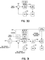
- a color control system utilizing a conventional proportional-integral-derivative (PID) control loop is illustrated in Figure 30.
- measurements of color density are obtained by a color monitoring system (CMS) 220 and are compared to desired values at block 222.
- CMS color monitoring system
- the results of the comparison are fed to a PID loop 224, which produces control signals which are fed to the ink keys, and the ink keys are adjusted accordingly.
- the adjusted ink flow works its way through the ink-roller train and is deposited on the web.
- the control loop is repeated.
- the conventional control loop shown in Fig. 30 does not take into account the nonlinear relationship between ink density and ink thickness on the web and thus suffers from a significant nonlinearity.
- the ink film thickness is very low, a unit change in ink film thickness will result in a fairly large change in density.
- the same change in ink film thickness results in a fairly small change in density.
- the system gain may be four times as great at extremely low thickness as compared to that at nominal thickness.
- FIG. 31 A color control system which accounts for the ink density saturation effect, as well as other effects, is illustrated in Fig. 31.
- a color monitoring system which accurately measures the optical density of a printed image while the press is running is described in allowed U.S. Pat. App. Serial No. 08/434,928, invented by John C. Seymour, Jeffrey P. Rappette, Frank N. Vroman, Chia-Lin Chu, Bradly S. Moersfelder, Michael A. Gill and Karl R. Voss.
- a video camera is utilized to acquire sequential images in different ink key zones across the web. The video camera is moved laterally across the web in a series of steps to acquire images at different zones at intervals of approximately one second.
- control loop of Fig. 31 has been converted from a "density control loop" as described in the conventional model to an "ink film thickness control loop".
- a conversion circuit 230 converts the desired ink density into a desired ink film thickness
- a conversion circuit 232 converts the measured ink density into an ink film thickness value. Conversion circuits 230 and 232 incorporate the relationship of Equation 12.
- the ideal PID loop parameters will depend upon the gain of the system. If the PID parameters are too low, then the control loop will converge slowly. If the parameters are too high, the control loop will overcorrect, and oscillate. Ideally, the PID parameters represent a compromise between these conditions.
- the conventional control system does not take into account the relative ink utilization factor which is dependent on plate coverage.
- An adjustment of an ink key by a predetermined amount in an area of low plate coverage will result in a larger change in ink film thickness on the web (corresponding to a higher change in optical density) as compared to the same ink key adjustment in an area of high plate coverage.
- the variables P, I, and D are the "standard" PID parameters corresponding to 100% coverage, and the primed variables are the corresponding corrected variables. These corrections are accomplished by block 238, and take into account Equation 10.
- the effects of the vibrator rollers are also included in the color control system of Fig. 31.
- this is a deconvolution or deblurring problem, in which one seeks to find the ink key settings given an ink key distribution function and a desired ink distribution.
- the ink density measurements for a respective ink key zones reach the PID loop serially in time rather than all at once.
- the problem would be one of trying to determine the optimal corrections based on a vector of ink film thickness errors.
- the vector of density errors is constrained to have all but one of the elements set to zero.
- one method to obtain the ink key settings is by determining the inverse of the ink key distribution function and convolving it with the ink film thickness error vector at block 240. Because the elements of the inking system model are linear, the result of taking the keys one at a time and summing them is the same as taking them on all at once.
- the control algorithm may call for an ink key setting which is beyond the physical limits of an ink key.
- the requested ink key setting may be for an opening greater than 100%, or for a setting which is negative.
- requested ink key openings which are out of range are merely clipped, so that they do not go beyond the extreme values.
- the correction is straightforward. If, for example, the requested ink key opening is 120%, the current ratchet setting must be increased to at least 1.2 times its current value. In this case, the new ink key opening would be set to 100%. Alternatively, it may be preferred to increase the ratchet setting 10% higher in order to allow for some further range of adjustment.
- an ink key opening is requested to go negative, it may not be possible to attain the target densities.
- One example is an ink key zone with very low coverage which is adjacent to an ink key zone with very high coverage.
- the ink spread by the vibrator rollers from the adjacent ink key zone may already be excessive. Clipping the ink key opening (that is, setting it to zero) will avoid requesting the ink key to move beyond its limit, but it may not yield optimal densities.
- the suboptimal densities result from the fact that compensation for the effects of the vibrator rollers will require changes in ink key openings for a multiplicity of ink keys. If only a single ink key is clipped, there may not be adequate compensation. As a worst case example, if an above-target density measurement is made in ink key zone i , and that ink key is already at zero, it is not necessary to move the neighboring ink keys to compensate for an ink key change which could not be made.
- ink key changes which improve upon these suboptimal conditions are vector clipping.
- measurements are made in one ink key zone at a time. Due to the compensation for the effects of the vibrator rollers, each density measurement gives rise to a vector of ink key changes, spread out over a multiplicity of ink keys. If any of these ink key changes results in an ink key which is out of range, then the magnitude of each individual ink key change is multiplied by a constant small enough so that no ink key is requested to go out of range. Thus, the entire ink key opening change vector is scaled to keep all the ink key openings within range.
- Equation 25 represents the pure delay time for the ink to pass through the ink train and flow onto the paper.
- PID loop 236 uses an integral term which is inversely proportional to the sum of the flow of ink due to coverage in the zone of interest, plus the ink back-flow amount.
- the examples disclosed have shown the well-known mechanical ink-key, the invention is equally applicable to other devices which regulate the flow of ink. Furthermore, although the examples are based on the Harris-Heidelberg M1000B print unit, the invention is equally applicable to other ink-train designs.
Landscapes
- Inking, Control Or Cleaning Of Printing Machines (AREA)
Abstract
Description


Claims (42)
- A method for determining initial settings for a plurality of ink control devices in a printing press wherein the ink control devices control the amount of ink supplied to respective zones of a first roller, wherein ink is transferred from the first roller to a roller train and then to a substrate to print an image, wherein the ink control devices are associated with respective ink key zones on the substrate, and wherein the roller train includes a plate cylinder, the method comprising,determining a non-proportional plate coverage equation which relates a plate coverage value to the corresponding ink film thickness on the plate cylinder needed to obtain a predetermined ink film thickness on the substrate, andcomputing an initial setting for each ink control device based on the non-proportional plate coverage equation given a plate coverage value for each respective ink key zone.
- The method of claim 1 wherein the non-proportional plate coverage equation is a linear plate coverage equation having a nonzero offset.
- The method of claim 1 wherein the non-proportional plate coverage equation is a model-based plate coverage equation.
- The method of claim 1 wherein the non-proportional plate coverage equation is an empirically derived plate coverage equation.
- A method for determining initial settings for a plurality of ink control devices in a printing press wherein the ink control devices control the amount of ink supplied to respective zones of a first roller, wherein ink is transferred from the first roller to a roller train and then to a substrate to print an image, wherein the ink control devices are associated with respective ink key zones on the substrate, and wherein the roller train includes a plate cylinder, the method comprising,determining a plate coverage equation which relates a plate coverage value to the corresponding ink film thickness on the plate cylinder needed to obtain a predetermined ink film thickness on the substrate,determining a non-proportional ink saturation density equation which relates the ink density on the substrate to the ink film thickness on the substrate, andcomputing an initial setting for each ink control device based on the plate coverage equation given a plate coverage value for each respective ink key zone and a desired optical density of ink on the substrate, wherein the desired optical density of ink is converted to a desired ink film thickness on the substrate according to the ink saturation density equation.
- The method of claim 5 wherein the plate coverage equation is a non-proportional plate coverage equation.
- The method of claim 6 wherein the non-proportional plate coverage equation is a linear plate coverage equation with a nonzero offset.
- The method of claim 6 wherein the non-proportional plate coverage equation is a model-based plate coverage equation.
- The method of claim 6 wherein the non-proportional plate coverage equation is an empirically derived plate coverage equation.
- The method of claim 5 wherein the plate coverage equation is a proportional plate coverage equation.
- A method for determining initial settings for a plurality of ink control devices in a printing press wherein the ink control devices control the amount of ink supplied to respective zones of a first roller, wherein ink is transferred from the first roller to a roller train and then to a substrate to print an image, wherein the ink control devices are associated with respective ink key zones on the substrate, and wherein the roller train includes a plate cylinder and a vibrator roller that moves back and forth in a lateral direction with respect to the longitudinal direction of movement of the substrate, the method comprising,determining an ink key distribution function which relates the amount of ink supplied by a single ink control device to the distribution of ink on the substrate in a plurality of affected ink key zones due to the lateral movement of the vibrator roller, andcomputing an initial setting for each ink control device based on the ink key distribution function given a plate coverage value for a respective ink key zone and a desired optical density of ink on the substrate.
- The method of claim 11 wherein the step of computing an initial setting for each ink key control device includes performing a deconvolution of the ink key distribution function with the desired ink film thicknesses on the plate cylinder for the respective ink key zones to obtain a desired ink film thickness on the first roller for each respective ink key zone.
- The method of claim 12 wherein the step of performing a deconvolution includes the use of Fourier transforms.
- The method of claim 13 wherein the step of performing a deconvolution includes the use of fast Fourier transforms.
- The method of claim 12 wherein the step of performing a deconvolution includes performing a Wiener deconvolution.
- The method of claim 11 wherein the step of computing an initial setting for each ink control device includes representing the desired ink film thickness on the plate cylinder for each respective ink key zone as a first array, representing the ink key distribution function as a first matrix, inverting the first matrix to obtain a second matrix, and performing a matrix multiplication of the second matrix with the first array to obtain a desired ink film thickness on the first roller for each respective ink key zone.
- The method of claim 16 wherein the first matrix is a Toeplitz matrix.
- The method of claim 16 wherein the first matrix is spatially variant.
- The method of claim 11 wherein the step of computing an initial setting for each ink control device includes representing the desired ink film thickness on the plate cylinder for each respective ink key zone as a first array, representing the ink key distribution function as a first matrix, generating a second matrix from the first matrix using singular value decomposition, and performing a matrix multiplication of the second matrix with the first array to obtain a desired ink film thickness on the first roller for each respective ink key zone.
- The method of claim 19 wherein the second matrix is spatially variant.
- The method of claim 11 further including the step of determining a plate coverage equation which relates a plate coverage value to the corresponding ink film thickness on the plate cylinder needed to obtain a predetermined ink film thickness on the substrate, and wherein the step of computing the initial setting for each ink control device includes the use of the plate coverage equation for determining the desired ink film thickness on the plate cylinder given a desired ink film thickness on the substrate and a plate coverage value for each respective ink key zone.
- The method of claim 21 wherein the plate coverage equation is a non-proportional plate coverage equation.
- The method of claim 21 wherein the non-proportional plate coverage equation is a linear plate coverage equation with a nonzero offset.
- The method of claim 21 wherein the non-proportional plate coverage equation is a model-based plate coverage equation.
- The method of claim 21 wherein the non-proportional plate coverage equation is an empirically derived plate coverage equation.
- The method of claim 21 wherein the plate coverage equation is a proportional plate coverage equation.
- The method of claim 21 further including the step of determining an ink saturation density function which relates the optical density of ink on the substrate to the ink film thickness on the substrate, and wherein the step of computing an initial setting for each ink control device includes computing a desired ink film thickness on the substrate for each respective ink key zone given a desired optical density of ink on the substrate.
- The method of claim 27 wherein the plate coverage equation is a non-proportional plate coverage equation.
- The method of claim 27 wherein the non-proportional plate coverage equation is a linear plate coverage equation with a nonzero offset.
- The method of claim 27 wherein the non-proportional plate coverage equation is a model-based plate coverage equation.
- The method of claim 27 wherein the nonproportional plate coverage equation is an empirically derived plate coverage equation.
- The method of claim 27 wherein the plate coverage equation is a proportional plate coverage equation.
- The method of claim 21 wherein the step of computing an initial setting for each ink control device includes performing a deconvolution of the ink key distribution function with the desired ink film thicknesses on the plate cylinder for the ink key zones to obtain a desired ink film thickness on the first roller for each respective ink key zone.
- The method of claim 33 wherein the step of performing a deconvolution includes the use of Fourier transforms.
- The method of claim 33 wherein the step of performing a deconvolution includes performing a Wiener deconvolution.
- The method of claim 21 wherein the step of computing an initial setting for each ink control device includes representing the desired ink film thickness on the plate cylinder for each respective ink key zone as a first array, representing the ink key distribution function as a first matrix, inverting the first matrix to obtain a second matrix, and performing a matrix multiplication of the second matrix with the first array to obtain a desired ink film thickness on the first roller for each respective ink key zone.
- The method of claim 36 wherein the second array is a Toeplitz matrix.
- The method of claim 21 wherein the step of computing an initial setting for each ink control device includes representing the desired ink film thickness on the plate cylinder for each respective ink key zone as a first array, representing the ink key distribution function as a first matrix, generating a second matrix from the first matrix using singular value decomposition, and performing a matrix multiplication of the second matrix with the first array to obtain a desired ink film thickness on the first roller for each respective ink key zone.
- The method of claim 11 further including the step of determining an ink saturation density function which relates the optical density of ink on the substrate to the ink film thickness on the substrate, and wherein the step of computing an initial setting for each ink control device includes computing a desired ink film thickness on the substrate for each respective ink key zone given a desired optical density of ink on the substrate.
- The method of claim 39 wherein the step of computing an initial setting for each ink control device includes performing a deconvolution of the ink key distribution function with the desired ink film thicknesses on the plate cylinder for the ink key zones to obtain a desired ink film thickness on the first roller for each respective ink key zone.
- The method of claim 40 wherein the step of performing a deconvolution includes the use of Fourier transforms.
- The method of claim 39 wherein the step of computing an initial setting for each ink control device includes representing the desired ink film thickness on the plate cylinder for each respective ink key zone as a first array, representing the ink key distribution function as a first matrix, inverting the first matrix to obtain a second matrix, and performing a matrix multiplication of the second matrix with the first array to obtain a desired ink film thickness on the first roller for each respective ink key zone.
Applications Claiming Priority (4)
| Application Number | Priority Date | Filing Date | Title |
|---|---|---|---|
| US4557097P | 1997-05-05 | 1997-05-05 | |
| US45570P | 1997-05-05 | ||
| US997288 | 1997-12-23 | ||
| US08/997,288 US5967049A (en) | 1997-05-05 | 1997-12-23 | Ink key control in a printing press including lateral ink spread, ink saturation, and back-flow compensation |
Publications (3)
| Publication Number | Publication Date |
|---|---|
| EP0881076A1 true EP0881076A1 (en) | 1998-12-02 |
| EP0881076B1 EP0881076B1 (en) | 2003-01-02 |
| EP0881076B2 EP0881076B2 (en) | 2009-03-11 |
Family
ID=26722934
Family Applications (1)
| Application Number | Title | Priority Date | Filing Date |
|---|---|---|---|
| EP98301254A Expired - Lifetime EP0881076B2 (en) | 1997-05-05 | 1998-02-20 | Ink key control system in a printing press |
Country Status (4)
| Country | Link |
|---|---|
| US (1) | US5967049A (en) |
| EP (1) | EP0881076B2 (en) |
| JP (1) | JP3364430B2 (en) |
| DE (1) | DE69810385T2 (en) |
Cited By (7)
| Publication number | Priority date | Publication date | Assignee | Title |
|---|---|---|---|---|
| EP1167033A1 (en) * | 2000-06-28 | 2002-01-02 | Heidelberger Druckmaschinen Aktiengesellschaft | Method for presetting an inking unit |
| US6546870B2 (en) | 1999-12-06 | 2003-04-15 | Heidelberger Druckmaschinen Ag | Method for controlling a quantity of ink in a printing machine |
| US6679171B2 (en) | 2000-03-03 | 2004-01-20 | Heidelberger Druckmaschinen Ag | Method of controlling an ink layer on a printing form of a printing machine |
| DE102013100916A1 (en) | 2013-01-30 | 2014-07-31 | Manroland Web Systems Gmbh | Method for controlling a parameter of an inking unit |
| DE10159698B4 (en) * | 2000-12-14 | 2015-03-26 | Heidelberger Druckmaschinen Ag | A method of adjusting an amount of ink supplied to a printing cylinder of a printing press |
| CN109760407A (en) * | 2019-03-09 | 2019-05-17 | 深圳市正鑫源实业有限公司 | The control method and its letterpress system of intelligent letterpress force of impression |
| CN111902290A (en) * | 2018-01-19 | 2020-11-06 | 鲍尔公司 | System and method for monitoring and adjusting decorator for containers |
Families Citing this family (39)
| Publication number | Priority date | Publication date | Assignee | Title |
|---|---|---|---|---|
| US6318266B1 (en) * | 1995-04-11 | 2001-11-20 | Scitex Corporation Ltd. | Ink flow rate indicator |
| DE19802920B4 (en) * | 1998-01-27 | 2008-01-31 | Man Roland Druckmaschinen Ag | Method and device for color control in printing machines |
| DE19822662C2 (en) * | 1998-05-20 | 2003-12-24 | Roland Man Druckmasch | Process for color reproduction on an image data oriented printing machine |
| DE19826810A1 (en) * | 1998-06-16 | 1999-12-23 | Koenig & Bauer Ag | Method and device for ink supply |
| JP3339835B2 (en) * | 1999-03-10 | 2002-10-28 | リョービ株式会社 | Ink supply control device and ink supply control method for printing press |
| EP1060886B1 (en) * | 1999-06-19 | 2002-07-31 | Koenig & Bauer Aktiengesellschaft | Method and device for feeding ink to ink fountains in printing machines |
| DE10009661B4 (en) * | 1999-06-19 | 2007-10-04 | Koenig & Bauer Aktiengesellschaft | Method and device for feeding printing ink in ink boxes of printing machines |
| JP3561459B2 (en) * | 2000-03-01 | 2004-09-02 | リョービ株式会社 | Ink supply control device |
| DE10152470B4 (en) * | 2000-11-23 | 2014-08-14 | Heidelberger Druckmaschinen Ag | Method for color presetting in multicolor printing |
| US6796240B2 (en) | 2001-06-04 | 2004-09-28 | Quad/Tech, Inc. | Printing press register control using colorpatch targets |
| JP3943873B2 (en) * | 2001-07-26 | 2007-07-11 | 大日本スクリーン製造株式会社 | Ink and water supply amount control device in printing machine and printing system provided with the same |
| JP2003154630A (en) * | 2001-08-06 | 2003-05-27 | Fuji Photo Film Co Ltd | Ink supplying device and printer |
| JP3880831B2 (en) * | 2001-10-10 | 2007-02-14 | 大日本スクリーン製造株式会社 | Ink preset method |
| JP2003118085A (en) * | 2001-10-10 | 2003-04-23 | Dainippon Screen Mfg Co Ltd | Printer |
| US6792863B2 (en) * | 2001-10-15 | 2004-09-21 | Dainippon Screen Mfg Co., Ltd. | Printing apparatus for automatically controlling ink supply device |
| JP4024593B2 (en) * | 2002-05-22 | 2007-12-19 | 大日本スクリーン製造株式会社 | Ink supply control device and printing device |
| US7187472B2 (en) | 2002-09-03 | 2007-03-06 | Innolutions, Inc. | Active color control for a printing press |
| US6938550B2 (en) * | 2002-10-31 | 2005-09-06 | R. R. Donnelley & Sons, Co. | System and method for print screen tonal control and compensation |
| US7017492B2 (en) * | 2003-03-10 | 2006-03-28 | Quad/Tech, Inc. | Coordinating the functioning of a color control system and a defect detection system for a printing press |
| JP4437392B2 (en) * | 2003-09-22 | 2010-03-24 | 大日本スクリーン製造株式会社 | Ink supply method and ink supply apparatus |
| US20050072328A1 (en) * | 2003-10-03 | 2005-04-07 | Gilliam Ronald D. | Automated system to control printing contact pressure |
| US7481509B2 (en) * | 2003-10-31 | 2009-01-27 | Hewlett-Packard Development Company, L.P. | Ink thickness consistency in digital printing presses |
| DE102004011239C5 (en) * | 2004-03-09 | 2023-07-27 | manroland sheetfed GmbH | Process for automatic color presetting on at least one inking unit of a printing press |
| US20050226466A1 (en) * | 2004-04-06 | 2005-10-13 | Quad/Tech, Inc. | Image acquisition assembly |
| US7423280B2 (en) * | 2004-08-09 | 2008-09-09 | Quad/Tech, Inc. | Web inspection module including contact image sensors |
| FI118759B (en) * | 2005-07-01 | 2008-03-14 | Upm Kymmene Oyj | Method and apparatus for controlling the quality of the imprint |
| US7477420B2 (en) * | 2005-09-07 | 2009-01-13 | Innolutions, Inc. | Barless closed loop color control |
| FR2895310B1 (en) * | 2005-12-23 | 2009-04-17 | Goss Int Montataire Sa | INK DEVICE AND CORRESPONDING ADJUSTMENT METHOD |
| JP2008120070A (en) * | 2006-10-18 | 2008-05-29 | Dainippon Screen Mfg Co Ltd | Printing machine controlling method and printing machine |
| DE102008041430B4 (en) * | 2008-08-21 | 2011-12-08 | Koenig & Bauer Aktiengesellschaft | Method for checking at least one measured value determined in a running printing process of a printing machine for its plausibility |
| DE102009033905A1 (en) * | 2008-08-22 | 2010-02-25 | Heidelberger Druckmaschinen Ag | Inking and dampening analysis |
| US8132887B2 (en) * | 2010-03-02 | 2012-03-13 | Innolutions, Inc. | Universal closed loop color control |
| US9138982B2 (en) * | 2011-04-27 | 2015-09-22 | Xerox Corporation | Image data based temperature control of a keyless inker |
| DE102012215114B4 (en) * | 2012-08-24 | 2015-03-19 | Koenig & Bauer Aktiengesellschaft | Method for inspecting a printed product |
| CN103350568B (en) * | 2013-07-22 | 2015-02-04 | 上海闻江电气控制设备有限公司 | Method for presetting ink amount of printing machine by adoption of mouse curve |
| EP3184303B1 (en) * | 2013-09-25 | 2018-09-05 | I. Mer Co., Ltd. | Ink supply device for printing machine |
| US10976263B2 (en) | 2016-07-20 | 2021-04-13 | Ball Corporation | System and method for aligning an inker of a decorator |
| US11034145B2 (en) | 2016-07-20 | 2021-06-15 | Ball Corporation | System and method for monitoring and adjusting a decorator for containers |
| CN113635671B (en) * | 2021-08-12 | 2023-02-03 | 深圳市凯印科技有限公司 | Intelligent ink presetting method and system |
Citations (2)
| Publication number | Priority date | Publication date | Assignee | Title |
|---|---|---|---|---|
| US3958509A (en) * | 1974-06-13 | 1976-05-25 | Harris Corporation | Image scan and ink control system |
| US4655135A (en) * | 1981-10-16 | 1987-04-07 | Harris Graphics Corporation | Adaptive control system for press presetting |
Family Cites Families (19)
| Publication number | Priority date | Publication date | Assignee | Title |
|---|---|---|---|---|
| US4008664A (en) * | 1973-07-23 | 1977-02-22 | Harris-Intertype Corporation | Ink key control system |
| JPS5952069B2 (en) * | 1977-12-15 | 1984-12-18 | 凸版印刷株式会社 | Ink usage prediction device |
| US4180741A (en) * | 1978-06-07 | 1979-12-25 | Harris Corporation | Apparatus for determining image areas for printing with calibration |
| GB2024457B (en) † | 1978-06-07 | 1983-01-06 | Harris Corp | Printing press ready and control system |
| US4187435A (en) * | 1978-06-07 | 1980-02-05 | Harris Corporation | Apparatus for determining image areas for printing with correction for extraneous matter |
| US4210818A (en) * | 1978-06-07 | 1980-07-01 | Harris Corporation | Apparatus for determining image areas for printing |
| US4512662A (en) * | 1981-07-06 | 1985-04-23 | Tobias Philip E | Plate scanner for printing plates |
| DE3220800C2 (en) * | 1982-06-03 | 1986-10-30 | M.A.N.- Roland Druckmaschinen AG, 6050 Offenbach | Device for scanning printing plates |
| DE3302798C2 (en) * | 1983-01-28 | 1987-03-05 | M.A.N.- Roland Druckmaschinen AG, 6050 Offenbach | Device for presetting on printing machines |
| DE3465930D1 (en) * | 1983-11-04 | 1987-10-15 | Gretag Ag | Method and device for controlling the ink supply in an offset printing machine, and offset printing machine provided with such a device |
| US5052298A (en) * | 1985-05-09 | 1991-10-01 | Graphics Microsystems | Ink control system |
| DE3910330A1 (en) * | 1988-03-30 | 1989-10-12 | Dainippon Printing Co Ltd | Printing machine |
| DE3829341A1 (en) * | 1988-08-30 | 1990-03-08 | Roland Man Druckmasch | DATA COLLECTION FOR COLOR CONTROL SYSTEMS |
| DE4004056A1 (en) * | 1990-02-10 | 1991-08-14 | Roland Man Druckmasch | Inking control esp. for offset rotary printing machine - applies colour pattern corrections before addn. of values extracted by scanning system from original colour documents |
| US5129320A (en) * | 1991-03-27 | 1992-07-14 | Rockwell International Corporation | Method for controlling viscous ink application in a printing press |
| US5138944A (en) * | 1991-09-03 | 1992-08-18 | Heidelberg Harris Inc. | Method and apparatus for setting respective positions of ink keys |
| US5224421A (en) * | 1992-04-28 | 1993-07-06 | Heidelberg Harris, Inc. | Method for color adjustment and control in a printing press |
| FI95888C (en) * | 1993-04-26 | 1996-04-10 | Valtion Teknillinen | Printing quality control procedure |
| JPH07227958A (en) * | 1994-02-17 | 1995-08-29 | Komori Corp | Ink supply amount control method and apparatus of printing press |
-
1997
- 1997-12-23 US US08/997,288 patent/US5967049A/en not_active Expired - Lifetime
-
1998
- 1998-02-20 EP EP98301254A patent/EP0881076B2/en not_active Expired - Lifetime
- 1998-02-20 DE DE69810385T patent/DE69810385T2/en not_active Expired - Fee Related
- 1998-05-06 JP JP12370398A patent/JP3364430B2/en not_active Expired - Fee Related
Patent Citations (2)
| Publication number | Priority date | Publication date | Assignee | Title |
|---|---|---|---|---|
| US3958509A (en) * | 1974-06-13 | 1976-05-25 | Harris Corporation | Image scan and ink control system |
| US4655135A (en) * | 1981-10-16 | 1987-04-07 | Harris Graphics Corporation | Adaptive control system for press presetting |
Cited By (9)
| Publication number | Priority date | Publication date | Assignee | Title |
|---|---|---|---|---|
| US6546870B2 (en) | 1999-12-06 | 2003-04-15 | Heidelberger Druckmaschinen Ag | Method for controlling a quantity of ink in a printing machine |
| US6679171B2 (en) | 2000-03-03 | 2004-01-20 | Heidelberger Druckmaschinen Ag | Method of controlling an ink layer on a printing form of a printing machine |
| EP1167033A1 (en) * | 2000-06-28 | 2002-01-02 | Heidelberger Druckmaschinen Aktiengesellschaft | Method for presetting an inking unit |
| US6477954B1 (en) | 2000-06-28 | 2002-11-12 | Heidelberger Druckmaschinen Ag | Ink key presetting system for offset printing machines |
| DE10159698B4 (en) * | 2000-12-14 | 2015-03-26 | Heidelberger Druckmaschinen Ag | A method of adjusting an amount of ink supplied to a printing cylinder of a printing press |
| DE102013100916A1 (en) | 2013-01-30 | 2014-07-31 | Manroland Web Systems Gmbh | Method for controlling a parameter of an inking unit |
| EP2762316A2 (en) | 2013-01-30 | 2014-08-06 | manroland web systems GmbH | Method for controlling a parameter of an inking system |
| CN111902290A (en) * | 2018-01-19 | 2020-11-06 | 鲍尔公司 | System and method for monitoring and adjusting decorator for containers |
| CN109760407A (en) * | 2019-03-09 | 2019-05-17 | 深圳市正鑫源实业有限公司 | The control method and its letterpress system of intelligent letterpress force of impression |
Also Published As
| Publication number | Publication date |
|---|---|
| DE69810385D1 (en) | 2003-02-06 |
| JP3364430B2 (en) | 2003-01-08 |
| DE69810385T2 (en) | 2003-10-30 |
| US5967049A (en) | 1999-10-19 |
| JPH10315439A (en) | 1998-12-02 |
| EP0881076B2 (en) | 2009-03-11 |
| EP0881076B1 (en) | 2003-01-02 |
Similar Documents
| Publication | Publication Date | Title |
|---|---|---|
| EP0881076B1 (en) | Ink key control system in a printing press | |
| US6318260B1 (en) | Ink key control in a printing press including lateral ink spread, ink saturation, and back-flow compensation | |
| US5967050A (en) | Markless color control in a printing press | |
| EP1000739A2 (en) | Color control system and method for a printing press | |
| EP1712361B1 (en) | Ink separation device for printing press ink feed control | |
| JPH054330A (en) | Ink control and method for preconditioning ink amount adjusting element for each zone | |
| EP1464493B2 (en) | A printing press | |
| JP2000313103A (en) | Method for adjusting inking in printing by press | |
| US20190240971A1 (en) | System and method for controlling color characteristics of a printed image | |
| US7000544B2 (en) | Measurement and regulation of inking in web printing | |
| JP2003136681A (en) | Ink controlling model for control of ink feed in machine for processing body to be printed | |
| EP1977899A1 (en) | Picture tone controller of printer and picture tone control method | |
| JP2008247047A (en) | Method for adjusting quantity of ink and apparatus for printing printed matter to be printed | |
| US5148747A (en) | Process for setting a production run ink zone profile | |
| US6742452B2 (en) | Method for presetting an ink feed in multi-color printing | |
| Englund et al. | Ink flow control by multiple models in an offset lithographic printing process | |
| US7450272B2 (en) | Method and system for printing management | |
| EP0922580A2 (en) | Color control system for a printing press | |
| US20080094646A1 (en) | Method and apparatus for estimating ink strike-through in printing press | |
| US5592880A (en) | Method of supplying or feeding dampening solution | |
| JP3121999B2 (en) | How to supply printing ink | |
| Răzvan-George | Real time quality control of the heatset offset printing process | |
| JP4192507B2 (en) | Integrated printing color tone control method and apparatus | |
| US20120145020A1 (en) | Device for regulating the application of dampening solution and ink in a printing press | |
| JPH11240141A (en) | Half-tone dot wall forming control device |
Legal Events
| Date | Code | Title | Description |
|---|---|---|---|
| PUAI | Public reference made under article 153(3) epc to a published international application that has entered the european phase |
Free format text: ORIGINAL CODE: 0009012 |
|
| AK | Designated contracting states |
Kind code of ref document: A1 Designated state(s): DE FR GB IT NL |
|
| AX | Request for extension of the european patent |
Free format text: AL;LT;LV;MK;RO;SI |
|
| 17P | Request for examination filed |
Effective date: 19990401 |
|
| AKX | Designation fees paid |
Free format text: AT BE CH DE DK LI |
|
| RBV | Designated contracting states (corrected) |
Designated state(s): DE FR GB IT NL |
|
| GRAG | Despatch of communication of intention to grant |
Free format text: ORIGINAL CODE: EPIDOS AGRA |
|
| GRAG | Despatch of communication of intention to grant |
Free format text: ORIGINAL CODE: EPIDOS AGRA |
|
| GRAH | Despatch of communication of intention to grant a patent |
Free format text: ORIGINAL CODE: EPIDOS IGRA |
|
| 17Q | First examination report despatched |
Effective date: 20020121 |
|
| GRAH | Despatch of communication of intention to grant a patent |
Free format text: ORIGINAL CODE: EPIDOS IGRA |
|
| GRAA | (expected) grant |
Free format text: ORIGINAL CODE: 0009210 |
|
| AK | Designated contracting states |
Kind code of ref document: B1 Designated state(s): DE FR GB IT NL |
|
| PG25 | Lapsed in a contracting state [announced via postgrant information from national office to epo] |
Ref country code: NL Free format text: LAPSE BECAUSE OF FAILURE TO SUBMIT A TRANSLATION OF THE DESCRIPTION OR TO PAY THE FEE WITHIN THE PRESCRIBED TIME-LIMIT Effective date: 20030102 Ref country code: FR Free format text: LAPSE BECAUSE OF FAILURE TO SUBMIT A TRANSLATION OF THE DESCRIPTION OR TO PAY THE FEE WITHIN THE PRESCRIBED TIME-LIMIT Effective date: 20030102 |
|
| REG | Reference to a national code |
Ref country code: GB Ref legal event code: FG4D Free format text: 20030102 |
|
| REF | Corresponds to: |
Ref document number: 69810385 Country of ref document: DE Date of ref document: 20030206 Kind code of ref document: P |
|
| PGFP | Annual fee paid to national office [announced via postgrant information from national office to epo] |
Ref country code: FR Payment date: 20030225 Year of fee payment: 6 |
|
| PGFP | Annual fee paid to national office [announced via postgrant information from national office to epo] |
Ref country code: NL Payment date: 20030227 Year of fee payment: 6 |
|
| PLBQ | Unpublished change to opponent data |
Free format text: ORIGINAL CODE: EPIDOS OPPO |
|
| PLBI | Opposition filed |
Free format text: ORIGINAL CODE: 0009260 |
|
| PLAX | Notice of opposition and request to file observation + time limit sent |
Free format text: ORIGINAL CODE: EPIDOSNOBS2 |
|
| EN | Fr: translation not filed | ||
| 26 | Opposition filed |
Opponent name: ABB SCHWEIZ AG Effective date: 20030929 |
|
| PLAX | Notice of opposition and request to file observation + time limit sent |
Free format text: ORIGINAL CODE: EPIDOSNOBS2 |
|
| PLBB | Reply of patent proprietor to notice(s) of opposition received |
Free format text: ORIGINAL CODE: EPIDOSNOBS3 |
|
| PGFP | Annual fee paid to national office [announced via postgrant information from national office to epo] |
Ref country code: GB Payment date: 20080227 Year of fee payment: 11 |
|
| PGFP | Annual fee paid to national office [announced via postgrant information from national office to epo] |
Ref country code: DE Payment date: 20080331 Year of fee payment: 11 |
|
| PGFP | Annual fee paid to national office [announced via postgrant information from national office to epo] |
Ref country code: IT Payment date: 20080227 Year of fee payment: 10 |
|
| PUAH | Patent maintained in amended form |
Free format text: ORIGINAL CODE: 0009272 |
|
| STAA | Information on the status of an ep patent application or granted ep patent |
Free format text: STATUS: PATENT MAINTAINED AS AMENDED |
|
| 27A | Patent maintained in amended form |
Effective date: 20090311 |
|
| AK | Designated contracting states |
Kind code of ref document: B2 Designated state(s): DE FR GB IT NL |
|
| PG25 | Lapsed in a contracting state [announced via postgrant information from national office to epo] |
Ref country code: IT Free format text: LAPSE BECAUSE OF NON-PAYMENT OF DUE FEES Effective date: 20080220 |
|
| GBPC | Gb: european patent ceased through non-payment of renewal fee |
Effective date: 20090220 |
|
| PG25 | Lapsed in a contracting state [announced via postgrant information from national office to epo] |
Ref country code: DE Free format text: LAPSE BECAUSE OF NON-PAYMENT OF DUE FEES Effective date: 20090901 |
|
| PG25 | Lapsed in a contracting state [announced via postgrant information from national office to epo] |
Ref country code: GB Free format text: LAPSE BECAUSE OF NON-PAYMENT OF DUE FEES Effective date: 20090220 |