EP0879960A2 - High pressure fuel pump - Google Patents
High pressure fuel pump Download PDFInfo
- Publication number
- EP0879960A2 EP0879960A2 EP98109088A EP98109088A EP0879960A2 EP 0879960 A2 EP0879960 A2 EP 0879960A2 EP 98109088 A EP98109088 A EP 98109088A EP 98109088 A EP98109088 A EP 98109088A EP 0879960 A2 EP0879960 A2 EP 0879960A2
- Authority
- EP
- European Patent Office
- Prior art keywords
- high pressure
- bellows
- pressure fuel
- fuel pump
- piston
- Prior art date
- Legal status (The legal status is an assumption and is not a legal conclusion. Google has not performed a legal analysis and makes no representation as to the accuracy of the status listed.)
- Granted
Links
- 239000000446 fuel Substances 0.000 title claims abstract description 97
- 239000004809 Teflon Substances 0.000 claims abstract description 6
- 229920006362 Teflon® Polymers 0.000 claims abstract description 6
- 239000000463 material Substances 0.000 claims abstract description 6
- 230000002093 peripheral effect Effects 0.000 claims description 5
- 229910000906 Bronze Inorganic materials 0.000 claims description 3
- OAICVXFJPJFONN-UHFFFAOYSA-N Phosphorus Chemical compound [P] OAICVXFJPJFONN-UHFFFAOYSA-N 0.000 claims description 3
- 239000010974 bronze Substances 0.000 claims description 3
- KUNSUQLRTQLHQQ-UHFFFAOYSA-N copper tin Chemical compound [Cu].[Sn] KUNSUQLRTQLHQQ-UHFFFAOYSA-N 0.000 claims description 3
- 238000007599 discharging Methods 0.000 claims description 3
- 239000011347 resin Substances 0.000 claims description 3
- 229920005989 resin Polymers 0.000 claims description 3
- 238000002485 combustion reaction Methods 0.000 description 4
- 239000003502 gasoline Substances 0.000 description 4
- 239000004519 grease Substances 0.000 description 4
- 238000012986 modification Methods 0.000 description 4
- 230000004048 modification Effects 0.000 description 4
- 238000007789 sealing Methods 0.000 description 3
- 239000002828 fuel tank Substances 0.000 description 2
- 239000002184 metal Substances 0.000 description 2
- 229910052751 metal Inorganic materials 0.000 description 2
- 238000000034 method Methods 0.000 description 2
- 229910052782 aluminium Inorganic materials 0.000 description 1
- XAGFODPZIPBFFR-UHFFFAOYSA-N aluminium Chemical compound [Al] XAGFODPZIPBFFR-UHFFFAOYSA-N 0.000 description 1
- 238000007796 conventional method Methods 0.000 description 1
- 239000000314 lubricant Substances 0.000 description 1
- 238000004519 manufacturing process Methods 0.000 description 1
- 238000003825 pressing Methods 0.000 description 1
Images


Classifications
-
- F—MECHANICAL ENGINEERING; LIGHTING; HEATING; WEAPONS; BLASTING
- F04—POSITIVE - DISPLACEMENT MACHINES FOR LIQUIDS; PUMPS FOR LIQUIDS OR ELASTIC FLUIDS
- F04B—POSITIVE-DISPLACEMENT MACHINES FOR LIQUIDS; PUMPS
- F04B53/00—Component parts, details or accessories not provided for in, or of interest apart from, groups F04B1/00 - F04B23/00 or F04B39/00 - F04B47/00
- F04B53/04—Draining
-
- F—MECHANICAL ENGINEERING; LIGHTING; HEATING; WEAPONS; BLASTING
- F04—POSITIVE - DISPLACEMENT MACHINES FOR LIQUIDS; PUMPS FOR LIQUIDS OR ELASTIC FLUIDS
- F04B—POSITIVE-DISPLACEMENT MACHINES FOR LIQUIDS; PUMPS
- F04B1/00—Multi-cylinder machines or pumps characterised by number or arrangement of cylinders
- F04B1/12—Multi-cylinder machines or pumps characterised by number or arrangement of cylinders having cylinder axes coaxial with, or parallel or inclined to, main shaft axis
- F04B1/14—Multi-cylinder machines or pumps characterised by number or arrangement of cylinders having cylinder axes coaxial with, or parallel or inclined to, main shaft axis having stationary cylinders
- F04B1/141—Details or component parts
-
- F—MECHANICAL ENGINEERING; LIGHTING; HEATING; WEAPONS; BLASTING
- F04—POSITIVE - DISPLACEMENT MACHINES FOR LIQUIDS; PUMPS FOR LIQUIDS OR ELASTIC FLUIDS
- F04B—POSITIVE-DISPLACEMENT MACHINES FOR LIQUIDS; PUMPS
- F04B1/00—Multi-cylinder machines or pumps characterised by number or arrangement of cylinders
- F04B1/12—Multi-cylinder machines or pumps characterised by number or arrangement of cylinders having cylinder axes coaxial with, or parallel or inclined to, main shaft axis
- F04B1/14—Multi-cylinder machines or pumps characterised by number or arrangement of cylinders having cylinder axes coaxial with, or parallel or inclined to, main shaft axis having stationary cylinders
- F04B1/141—Details or component parts
- F04B1/146—Swash plates; Actuating elements
-
- F—MECHANICAL ENGINEERING; LIGHTING; HEATING; WEAPONS; BLASTING
- F04—POSITIVE - DISPLACEMENT MACHINES FOR LIQUIDS; PUMPS FOR LIQUIDS OR ELASTIC FLUIDS
- F04B—POSITIVE-DISPLACEMENT MACHINES FOR LIQUIDS; PUMPS
- F04B53/00—Component parts, details or accessories not provided for in, or of interest apart from, groups F04B1/00 - F04B23/00 or F04B39/00 - F04B47/00
- F04B53/14—Pistons, piston-rods or piston-rod connections
- F04B53/143—Sealing provided on the piston
-
- F—MECHANICAL ENGINEERING; LIGHTING; HEATING; WEAPONS; BLASTING
- F05—INDEXING SCHEMES RELATING TO ENGINES OR PUMPS IN VARIOUS SUBCLASSES OF CLASSES F01-F04
- F05C—INDEXING SCHEME RELATING TO MATERIALS, MATERIAL PROPERTIES OR MATERIAL CHARACTERISTICS FOR MACHINES, ENGINES OR PUMPS OTHER THAN NON-POSITIVE-DISPLACEMENT MACHINES OR ENGINES
- F05C2201/00—Metals
- F05C2201/04—Heavy metals
- F05C2201/0469—Other heavy metals
- F05C2201/0475—Copper or alloys thereof
- F05C2201/0478—Bronze (Cu/Sn alloy)
-
- F—MECHANICAL ENGINEERING; LIGHTING; HEATING; WEAPONS; BLASTING
- F05—INDEXING SCHEMES RELATING TO ENGINES OR PUMPS IN VARIOUS SUBCLASSES OF CLASSES F01-F04
- F05C—INDEXING SCHEME RELATING TO MATERIALS, MATERIAL PROPERTIES OR MATERIAL CHARACTERISTICS FOR MACHINES, ENGINES OR PUMPS OTHER THAN NON-POSITIVE-DISPLACEMENT MACHINES OR ENGINES
- F05C2225/00—Synthetic polymers, e.g. plastics; Rubber
- F05C2225/04—PTFE [PolyTetraFluorEthylene]
Definitions
- the present invention relates to a high pressure fuel pump, and more particularly, to a high pressure fuel pump for increasing a fuel pressure supplied to an internal combustion engine.
- a high pressure fuel pump there is a conventionally known plunger pump which pressurizes a fuel by a plunger sliding in a cylinder.
- a plunger pump which pressurizes a fuel by a plunger sliding in a cylinder.
- a gasoline having a relatively low viscosity as the fuel a fuel leaked from a clearance between the cylinder and the plunger enters into a mechanical sliding portion which reciprocates the plunger through a driving shaft. Therefore, since the mechanical sliding portion can not be lubricated using grease or oil, a product in which the mechanical sliding portion is lubricated by gasoline has become commercially practical. However, a product in which the gasoline is used as a lubricant does not have sufficient mechanical efficiency and durability.
- the former publication discloses an axial swash plate bellows type fuel pump in which a thrust bearing is mounted to an inclined brim portion of a rotating shaft to form a swash plate, and a plurality of pump chambers constituted by bellows are sequentially expanded and contracted by rotating the swash plate, thereby pressurizing the fuel supplied into the pump chambers.
- the pump chamber is constituted by the bellows, it is possible to prevent the fuel from leaking from the pump chamber.
- the pump in order to reduce a discharge pulse, the pump has a plurality of plungers and is formed into an axial plunger shape in generally. In this case, if a seal diaphragm is provided for every plunger, its size is increased and is not practical.
- a bellows is disposed such as to surround the piston such that opposite ends of the bellows are fixed, through a seal member, to an outer end of the piston and to a portion of the body in the vicinity of the cylinder and a fuel leaked from a sliding clearance between the piston and the cylinder is sealed by the bellows.
- a space surrounded by the bellows and a return passage is connected to each other directly or through a groove so that a large internal pressure is not applied to the bellows.
- the bellows can be made of low-priced material having smaller operating resistance and excellent adhesion property with respect to the piston operation such as Teflon.
- the bellows is formed at its outer end at the side of the body with a recess, and a portion of a bellows-holding plate is fitted in the recess so that the plurality of fuel pumps can be disposed compactly.
- a rotating shaft is provided at its tip end with: a disc-like swash plate obliquely coupled to the rotating shaft; thrust ball bearings disposed around the disc-like swash plate; and piston shoe guide plates each swings by a force transmitted through the thrust ball bearing when the rotating shaft is rotated; and each of the piston shoe guide plates is slidably supported by a spherical portion provided at a tip end of a rod which stands on a center of a body of the high pressure fuel pump.
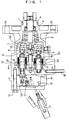
- Fig.1 is a sectional view of a high pressure fuel pump according to an embodiment of the present invention.
- a case 1 of the high pressure fuel pump is provided at its outer end with fixtures for mounting the case 1 to a portion of a cylinder head of an internal combustion engine (not shown), e.g., holes 2a and 2b through which bolts are passed.
- the case 1 rotatably supports a rotating shaft 4 through a bearing 3 on a center line within the case 1.
- An oil seal 5 is provided between the case 1 and the rotating shaft 4.
- the rotating shaft 4 is connected at its outer end with a camshaft (not shown) mounted to the cylinder head and is rotated.
- a rotating disc 7 is mounted to an inner end of the rotating shaft 4 such that the rotating disc 7 is inclined with respect to the rotating shaft.
- the rotating disc 7 is referred to as a swash plate 7 hereinafter.
- One of bearing races (9a) of the thrust ball bearing 9 is fixed to the swash plate 7, and the other bearing race 9b is fixed to a piston shoe guide plate 8 provided such as to oppose to the swash plate 7.
- a pump head 11 and a body 12 are coupled to each other by a bolt 13.
- the body 12 is provided on its center axis with a rod 14.
- the rod 14 is provided at its end projecting toward the swash plate 7 with a spherical portion 16.
- the rod 14 is pressed in a direction of the rotating shaft 4 by a spring 15 around the rod 14.
- the piston shoe guide plate 8 is provided at its central portion with a spherical receiving portion 20.
- the spherical receiving portion 20 accommodates the spherical tip end 16 of the rod 14.
- the piston shoe guide plate 8 is pushed and supported toward the swash plate 7 by the rod 14.
- the spherical receiving portion 20 can be made of material suitable for sliding movement, such as phosphor bronze.
- a supply passage 17 is a passage for supplying a fuel
- an output passage 18 is a passage for outputting a compressed fuel
- a return passage 19 is a passage for returning, to a fuel tank (not shown), a fuel leaked from a clearance between a cylinder and a piston of a fuel pump which will be described later.
- each of the fuel pumps 21 to 25 includes a cylinder 31 and a piston 32 reciprocating in the cylinder 31, a spherical portion 33 is mounted to an outer end of the piston 32, and a bellows 34 is provided outside the cylinder 31 and the piston 32 for completely sealing a fuel leaked from the clearance between the cylinder 31 and the piston 32.
- the bellows 34 is preferably made of resin such as Teflon.
- One end 34a of the bellows 34 is mounted to the piston 32 through an O-ring 35, and the other end 34b is mounted to the body 12 through another O-ring 36.
- the one end 34a is pushed toward the piston 32 through the O-ring 35 by a backup guide plate 37, and the other end 34b is guided by the cylinder 31.
- the cylinder 31 opposed to the other end 34b is formed at its outer peripheral surface with a fuel introducing passage 38 comprising a spiral groove. A fuel leaked from the sliding clearance between the cylinder 31 and the piston 32 is sent to the return passage 19 through the clearance between the bellows 34 and an outer wall of the cylinder 31 and through the introducing passage 38 comprising the spiral groove.
- the shape of the introducing passage 38 should not be limited to the spiral groove, and may be formed into other shape.
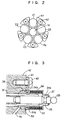
- each of the bellows 34 mounted to the five fuel pumps 21 to 25 is fixed to the body 12 by a bellows-holding plate 41 comprising a notched plate which opens in a circumferential direction so that the bellows 34 should not be loosed out from the body 12.
- the bellows-holding plate 41 is fixed to the body 12 by a screw 42. Since the bellows-holding plate 41 is designed such that it is fitted into a recess 34c formed in the other end 34b of the bellows 34, the five fuel pumps 21 to 25 can be disposed close to the rod 14 as shown in Fig.2. As a result, the high pressure fuel pump can be made smaller.
- the spherical portion 33 fixed to the outer tip end of the piston 32 of each of the fuel pumps 21 to 25 is accommodated in the piston shoe 43 of the piston shoe guide plate 8 as shown in Fig. 4.
- the piston shoe guide plate 8 is made of light metal such as aluminum for reducing the weight.
- the spherical receiving portion 20 is preferably made of material suitable for sliding movement such as phosphor bronze as described above.
- Intake valves 51 and discharge valves 52 respectively corresponding to the fuel pumps 21 to 25 are disposed in the pump head 11 shown in Fig.1.
- a fuel discharged from the discharge valve 52 is received from the output passage 18 through a cylindrical passage which is not shown, and is sent to the internal combustion engine.
- the five fuel pumps 21 to 25 sequentially conduct a cycle of drawing, compressing and discharging of fuel, cycle by cycle. As a result, the discharge pulse can be lowered.
- the drawing of fuel can be conducted by opening the intake valve 51 for drawing a fuel such as gasoline sent from the fuel tank through he supply passage 17.
- Fuel sequentially pressurized by the five fuel pumps 21 to 25 are collected to the cylindrical passage through respective discharge valves 52, and are sent to the internal combustion engine through the output passage 18.
- the bellows 34 can be made of low-priced and light resin such as Teflon.
- the thrust ball bearing 9 is interposed between the swash plate 7 coupled to the rotating shaft 4 and the piston shoe guide plate 8, the rotating force of the rotating shaft 4 can be absorbed by the thrust ball bearing 9. Therefore, a relative sliding motion of the piston shoe 43 is reduced, and the durability is enhanced. Furthermore, since the spherical portion 16 provided at the tip end of the rod 14 is received by the spherical receiving portion 20, the precession of the piston shoe guide plate 8 can be made more smoothly, and the durability of the piston shoe guide plate 8 can be enhanced.
- a modification of the spherical receiving portion 20 is explained with reference to Fig.5.
- This modification is characterized in that the spherical portion 16 provided at the tip end of the rod 14 is directly received by a spherical receiving portion which is integrally formed with the piston shoe guide 8.
- the spherical receiving portion 20 which was separate from the piston shoe guide plate 8 can be omitted, which can further reduce the price.
- FIG. 6 A second embodiment of the present invention will be described next with reference to Figs.6 and 7. Elements similar to those shown in Figs.2 and 3 are designated denoted by the same reference numerals.
- the one end 34a of the bellows 34 is mounted to the piston 32 by the plate-holding member 46, and the other end 34b is mounted to the body 12 by a screw 42 through the bellows-holding plate 45.
- the return passage 19 includes an entrance between an end of the cylinder 31 and the other end 34b of the bellows 34. Therefore, unlike the first embodiment, it is unnecessary to provide the spiral introducing passage 38 in the outer periphery of the cylinder 31.
- the second embodiment is inferior to the first embodiment in that the high pressure fuel pump can not be made smaller.
- the fuel leaked from the sliding clearance between the piston and the cylinder can be sealed completely by the bellows, it is possible to lubricate, using grease or oil, the mechanical sliding portion which translates the rotation of the driving shaft into the reciprocation of the piston, and it is possible to enhance the mechanical efficiency and the reliability.
- the bellows can be made of low-priced material such as Teflon. Therefore, the manufacturing cost of the high pressure fuel pump can be lowered.
- the bellows-holding member having an opening outside is formed in the bellows-holding plate, and the bellows-holding member is fitted to the recess formed in the outside of the end at the side of the body of the bellows, the plurality of fuel pumps can be disposed compactly, and the small high pressure fuel pump can be produced.
- the piston shoe guide plate recurringly pressing the pistons of the plurality of fuel pumps is swingably supported by the spherical portion provided at the tip end of the rod which stands at the center of the body of the high pressure fuel pump, it is possible to provide a reliable high pressure fuel pump having a long lifetime.
Landscapes
- Engineering & Computer Science (AREA)
- Mechanical Engineering (AREA)
- General Engineering & Computer Science (AREA)
- Reciprocating Pumps (AREA)
- Diaphragms And Bellows (AREA)
Abstract
Description
Claims (12)
- A high pressure fuel pump, in which a plurality of fuel pumps disposed circularly are recurringly operated to output high pressure fuel, comprising: a cylinder which is at least partially fixed to a body of said high pressure fuel pump; a piston reciprocating within said cylinder for drawing, compressing and discharging a fuel; and a bellows disposed such as to surround said piston such that opposite ends of said bellows are fixed, through a seal member, to an outer end of said piston and to a portion of said body in the vicinity of said cylinder.
- A high pressure fuel pump according to claim 1, wherein a leaked-fuel return passage having an entrance in a space surrounded by said bellows is provided.
- A high pressure fuel pump according to claim 1, wherein an end of said bellows at the side of said body includes an inner peripheral surface which is in contact with an outer periphery of a portion of said cylinder, a groove is formed in a contact portion of said outer periphery of the portion of said cylinder with said inner peripheral surface, and a fuel leaked from the sliding clearance between said piston and said cylinder is introduced into said leaked-fuel return passage through said groove.
- A high pressure fuel pump according to claim 3, wherein said groove is formed into a spiral shape.
- A high pressure fuel pump according to any one of claims 1 to 3, wherein said bellows is made of resin such as Teflon.
- A high pressure fuel pump according to claim 4 or 5, wherein said bellows is formed at its outer end at the side of said body with a recess, and a portion of a bellows-holding plate is fitted in said recess so that said plurality of fuel pumps can be disposed compactly.
- A high pressure fuel pump according to claim 6, wherein said bellows-holding plate includes an outwardly opened arc portion having a size corresponding to said recess formed at said outer end of said bellows at the side of said body, and said bellows-holding plate is fixed to said body.
- A high pressure fuel pump, in which a plurality of fuel pumps disposed circularly are recurringly operated to output high pressure fuel, wherein a rotating shaft is provided at its tip end with: a disc-like swash plate obliquely coupled to said rotating shaft; thrust ball bearings disposed around said disc-like swash plate; and piston shoe guide plates each swings by a force transmitted through said thrust ball bearing when said rotating shaft is rotated; and each of said piston shoe guide plates is slidably supported by a spherical portion provided at a tip end of a rod which stands on a center of a body of said high pressure fuel pump.
- A high pressure fuel pump according to claim 8, wherein said spherical portion provided at the tip end of said rod is accommodated in a spherical receiving portion provided at a center portion of said piston shoe guide plate.
- A high pressure fuel pump according to claim 9, wherein said spherical receiving portion is made of material suitable for sliding movement, such as phosphor bronze.
- A high pressure fuel pump according to claim 8, wherein said piston shoe guide plate is provided at its outer peripheral portion with a piston shoe accommodating spherical portions coupled to outer tip ends of pistons of said plurality of fuel pumps.
- A high pressure fuel pump according to claim 8, wherein said spherical portion provided at the tip end of said rod which stands at the center of said body of said high pressure fuel pump supports said piston shoe guide plate by a repulsive force of a spring.
Applications Claiming Priority (3)
| Application Number | Priority Date | Filing Date | Title |
|---|---|---|---|
| JP144597/97 | 1997-05-19 | ||
| JP14459797 | 1997-05-19 | ||
| JP9144597A JPH10318123A (en) | 1997-05-19 | 1997-05-19 | High pressure fuel pump |
Publications (3)
| Publication Number | Publication Date |
|---|---|
| EP0879960A2 true EP0879960A2 (en) | 1998-11-25 |
| EP0879960A3 EP0879960A3 (en) | 2000-03-22 |
| EP0879960B1 EP0879960B1 (en) | 2004-03-31 |
Family
ID=15365761
Family Applications (1)
| Application Number | Title | Priority Date | Filing Date |
|---|---|---|---|
| EP98109088A Expired - Lifetime EP0879960B1 (en) | 1997-05-19 | 1998-05-19 | High pressure fuel pump |
Country Status (4)
| Country | Link |
|---|---|
| US (1) | US6142060A (en) |
| EP (1) | EP0879960B1 (en) |
| JP (1) | JPH10318123A (en) |
| DE (1) | DE69822698T2 (en) |
Cited By (4)
| Publication number | Priority date | Publication date | Assignee | Title |
|---|---|---|---|---|
| EP0881379A3 (en) * | 1997-05-30 | 1999-07-21 | Mitsubishi Denki Kabushiki Kaisha | Fuel-feed system for an engine |
| WO2009144060A1 (en) * | 2008-05-30 | 2009-12-03 | Robert Bosch Gmbh | High-pressure fuel pump |
| CN103147951A (en) * | 2013-04-03 | 2013-06-12 | 西安航空学院 | Low-vibration three-cylinder three-action reciprocating pump |
| WO2015055332A1 (en) * | 2013-10-14 | 2015-04-23 | Continental Automotive Gmbh | High pressure pump |
Families Citing this family (19)
| Publication number | Priority date | Publication date | Assignee | Title |
|---|---|---|---|---|
| JP2001003839A (en) * | 1999-06-21 | 2001-01-09 | Hitachi Ltd | High pressure fuel pump |
| DE10038354C2 (en) * | 2000-08-05 | 2003-03-20 | Atlas Fahrzeugtechnik Gmbh | Control device for adjusting the angle of rotation of a camshaft |
| US6506033B2 (en) * | 2000-10-26 | 2003-01-14 | Okenseiko Co., Ltd. | Miniature pump with ball-plate drive |
| JP2003247487A (en) * | 2002-02-21 | 2003-09-05 | Sanden Corp | Swash plate compressor |
| JP2005288515A (en) * | 2004-04-02 | 2005-10-20 | Sintokogio Ltd | Press surface plate for press machine and press machine |
| US20050226737A1 (en) * | 2004-04-07 | 2005-10-13 | Sauer-Danfoss, Inc. | Axial piston hydraulic power unit with pseudo slippers |
| US7543992B2 (en) * | 2005-04-28 | 2009-06-09 | General Electric Company | High temperature rod end bearings |
| US7677155B2 (en) * | 2006-01-13 | 2010-03-16 | Gm Global Technology Operations, Inc. | Statically sealed high pressure fuel pump and method |
| US7313997B2 (en) * | 2006-05-26 | 2008-01-01 | Visteon Global Technologies, Inc. | Copper alloy piston shoe |
| US20120291625A1 (en) * | 2011-05-19 | 2012-11-22 | Roller Bearing Company Of America, Inc. | Nutating swash plate ball bearing assembly |
| DE102010011292A1 (en) * | 2010-03-13 | 2011-09-15 | Dr. Ing. H.C. F. Porsche Aktiengesellschaft | High-pressure fuel pump |
| DE102011053358A1 (en) | 2011-09-07 | 2013-03-07 | Dr. Ing. H.C. F. Porsche Aktiengesellschaft | Fuel pump, particularly single piston high-pressure fuel pump for internal combustion engines of passenger cars, has housing, piston mounted in housing and arranged in oil space of housing and drive shaft mounted in housing |
| JP5687257B2 (en) * | 2012-09-04 | 2015-03-18 | 川崎重工業株式会社 | Fuel pump |
| DE102013212565A1 (en) * | 2013-06-28 | 2014-12-31 | Robert Bosch Gmbh | High-pressure fuel pump |
| CN104791238A (en) * | 2014-01-17 | 2015-07-22 | 沈如华 | High-efficiency color paste color mixing pump |
| DE102016201039A1 (en) * | 2016-01-26 | 2017-02-23 | Continental Automotive Gmbh | High-pressure fuel pump |
| CN112196752A (en) * | 2020-10-09 | 2021-01-08 | 王小安 | A drive structure of a swash plate type plunger water pump without return spring |
| CN113236518B (en) * | 2021-02-07 | 2025-07-15 | 珠海市荣成科技有限公司 | Oil-water separation structure and water pump |
| IT202200026235A1 (en) * | 2022-12-21 | 2024-06-21 | Mixtron S R L | PISTON PUMP OF THE TYPE EQUIPPED WITH AT LEAST THREE PUMPING CHAMBERS |
Citations (2)
| Publication number | Priority date | Publication date | Assignee | Title |
|---|---|---|---|---|
| JPH0712029A (en) | 1993-06-24 | 1995-01-17 | Mitsubishi Electric Corp | High pressure fuel pump |
| JPH08232850A (en) | 1995-02-24 | 1996-09-10 | Nissan Motor Co Ltd | Bellows type pump |
Family Cites Families (7)
| Publication number | Priority date | Publication date | Assignee | Title |
|---|---|---|---|---|
| FR2454544A1 (en) * | 1979-04-19 | 1980-11-14 | Bronzavia Sa | Annular bellows seals for a reciprocating pump - to protect an oscillating disc mechanism from an aggressive environment e.g. sea water |
| US4776260A (en) * | 1980-11-07 | 1988-10-11 | Vincze Alexander L | Constant pressure pump |
| DE3140742A1 (en) * | 1981-10-14 | 1983-04-28 | Mannesmann Rexroth GmbH, 8770 Lohr | Pump, especially for the pumping of a toxic liquid |
| JPH0656162B2 (en) * | 1987-03-03 | 1994-07-27 | トヨタ自動車株式会社 | Variable stroke device |
| JP2503127B2 (en) * | 1991-06-10 | 1996-06-05 | 株式会社ヤマダコーポレーション | High viscosity pump device |
| FR2738883B1 (en) * | 1995-09-14 | 1997-10-24 | Valeo | HYDRAULICALLY CONTROLLED CLUTCH STOPPER FOR A DIAPHRAGM CLUTCH OF A MOTOR VEHICLE |
| JPH09112408A (en) * | 1995-10-19 | 1997-05-02 | Hitachi Ltd | Fuel pump |
-
1997
- 1997-05-19 JP JP9144597A patent/JPH10318123A/en active Pending
-
1998
- 1998-05-13 US US09/076,704 patent/US6142060A/en not_active Expired - Fee Related
- 1998-05-19 EP EP98109088A patent/EP0879960B1/en not_active Expired - Lifetime
- 1998-05-19 DE DE69822698T patent/DE69822698T2/en not_active Expired - Fee Related
Patent Citations (2)
| Publication number | Priority date | Publication date | Assignee | Title |
|---|---|---|---|---|
| JPH0712029A (en) | 1993-06-24 | 1995-01-17 | Mitsubishi Electric Corp | High pressure fuel pump |
| JPH08232850A (en) | 1995-02-24 | 1996-09-10 | Nissan Motor Co Ltd | Bellows type pump |
Cited By (5)
| Publication number | Priority date | Publication date | Assignee | Title |
|---|---|---|---|---|
| EP0881379A3 (en) * | 1997-05-30 | 1999-07-21 | Mitsubishi Denki Kabushiki Kaisha | Fuel-feed system for an engine |
| WO2009144060A1 (en) * | 2008-05-30 | 2009-12-03 | Robert Bosch Gmbh | High-pressure fuel pump |
| CN103147951A (en) * | 2013-04-03 | 2013-06-12 | 西安航空学院 | Low-vibration three-cylinder three-action reciprocating pump |
| WO2015055332A1 (en) * | 2013-10-14 | 2015-04-23 | Continental Automotive Gmbh | High pressure pump |
| US10132311B2 (en) | 2013-10-14 | 2018-11-20 | Continental Automotive Gmbh | High pressure pump |
Also Published As
| Publication number | Publication date |
|---|---|
| EP0879960B1 (en) | 2004-03-31 |
| EP0879960A3 (en) | 2000-03-22 |
| DE69822698D1 (en) | 2004-05-06 |
| US6142060A (en) | 2000-11-07 |
| JPH10318123A (en) | 1998-12-02 |
| DE69822698T2 (en) | 2005-02-10 |
Similar Documents
| Publication | Publication Date | Title |
|---|---|---|
| US6142060A (en) | High pressure fuel pump having a bellows sealing arrangement | |
| US5951261A (en) | Reversible drive compressor | |
| US5247873A (en) | Connecting rod assembly with a crosshead | |
| US4594055A (en) | Piston assembly for a refrigerant compressor | |
| US6328537B1 (en) | Radial piston pump | |
| WO1999043947A1 (en) | Fuel supply pump with dynamic plunger return | |
| KR20060051200A (en) | Axial displacement device of reciprocating | |
| US4444549A (en) | Refrigerant compressor | |
| US6217289B1 (en) | Axial piston pump with auxiliary pump | |
| US5131319A (en) | Wobble plate type refrigerant compressor having a ball-and-socket joint lubricating mechanism | |
| KR940010465B1 (en) | Low noise pump assembly | |
| US6321635B1 (en) | Swash plate type compressor in which lubricating oil is effectively supplied to a shoe mechanism interposed between a piston and a swash plate | |
| EP0844389B1 (en) | Swash plate compressor | |
| US6368071B1 (en) | High pressure fuel pump | |
| US5947698A (en) | Piston type compressor | |
| GB2171465A (en) | Refrigerant compressor | |
| US6224349B1 (en) | Reciprocating type compressor having orbiting valve plate | |
| CA2036212C (en) | Wobble plate type refrigerant compressor having a ball-and-socket joint lubricating mechanism | |
| US6036448A (en) | Fuel pump sealed in a bellows | |
| US20030145835A1 (en) | Drive shaft seal for gasoline direct injection pump | |
| US4756236A (en) | Gas compressor | |
| GB2309270A (en) | Radial plunger pump | |
| KR100887230B1 (en) | Gear oil pump of reciprocating machine | |
| JPH1082353A (en) | Fuel pump | |
| RU2231671C1 (en) | High-pressure fuel-injection pump |
Legal Events
| Date | Code | Title | Description |
|---|---|---|---|
| PUAI | Public reference made under article 153(3) epc to a published international application that has entered the european phase |
Free format text: ORIGINAL CODE: 0009012 |
|
| 17P | Request for examination filed |
Effective date: 19980519 |
|
| AK | Designated contracting states |
Kind code of ref document: A2 Designated state(s): DE FR GB |
|
| AX | Request for extension of the european patent |
Free format text: AL;LT;LV;MK;RO;SI |
|
| RIC1 | Information provided on ipc code assigned before grant |
Free format text: 7F 04B 1/14 A, 7F 04B 53/14 B, 7F 04B 53/04 B, 7F 02M 59/44 B |
|
| PUAL | Search report despatched |
Free format text: ORIGINAL CODE: 0009013 |
|
| AK | Designated contracting states |
Kind code of ref document: A3 Designated state(s): AT BE CH CY DE DK ES FI FR GB GR IE IT LI LU MC NL PT SE |
|
| AX | Request for extension of the european patent |
Free format text: AL;LT;LV;MK;RO;SI |
|
| AKX | Designation fees paid |
Free format text: DE FR GB |
|
| 17Q | First examination report despatched |
Effective date: 20030422 |
|
| GRAP | Despatch of communication of intention to grant a patent |
Free format text: ORIGINAL CODE: EPIDOSNIGR1 |
|
| GRAS | Grant fee paid |
Free format text: ORIGINAL CODE: EPIDOSNIGR3 |
|
| GRAA | (expected) grant |
Free format text: ORIGINAL CODE: 0009210 |
|
| AK | Designated contracting states |
Kind code of ref document: B1 Designated state(s): DE FR GB |
|
| REG | Reference to a national code |
Ref country code: GB Ref legal event code: FG4D |
|
| REF | Corresponds to: |
Ref document number: 69822698 Country of ref document: DE Date of ref document: 20040506 Kind code of ref document: P |
|
| PGFP | Annual fee paid to national office [announced via postgrant information from national office to epo] |
Ref country code: GB Payment date: 20040512 Year of fee payment: 7 |
|
| ET | Fr: translation filed | ||
| PLBE | No opposition filed within time limit |
Free format text: ORIGINAL CODE: 0009261 |
|
| STAA | Information on the status of an ep patent application or granted ep patent |
Free format text: STATUS: NO OPPOSITION FILED WITHIN TIME LIMIT |
|
| 26N | No opposition filed |
Effective date: 20050104 |
|
| PG25 | Lapsed in a contracting state [announced via postgrant information from national office to epo] |
Ref country code: GB Free format text: LAPSE BECAUSE OF NON-PAYMENT OF DUE FEES Effective date: 20050519 |
|
| GBPC | Gb: european patent ceased through non-payment of renewal fee |
Effective date: 20050519 |
|
| PGFP | Annual fee paid to national office [announced via postgrant information from national office to epo] |
Ref country code: FR Payment date: 20060515 Year of fee payment: 9 |
|
| PGFP | Annual fee paid to national office [announced via postgrant information from national office to epo] |
Ref country code: DE Payment date: 20070517 Year of fee payment: 10 |
|
| REG | Reference to a national code |
Ref country code: FR Ref legal event code: ST Effective date: 20080131 |
|
| PG25 | Lapsed in a contracting state [announced via postgrant information from national office to epo] |
Ref country code: FR Free format text: LAPSE BECAUSE OF NON-PAYMENT OF DUE FEES Effective date: 20070531 |
|
| PG25 | Lapsed in a contracting state [announced via postgrant information from national office to epo] |
Ref country code: DE Free format text: LAPSE BECAUSE OF NON-PAYMENT OF DUE FEES Effective date: 20081202 |