EP0878951B1 - Personal computer based image processing system for controlling image processing through a user interface of a scanner - Google Patents
Personal computer based image processing system for controlling image processing through a user interface of a scanner Download PDFInfo
- Publication number
- EP0878951B1 EP0878951B1 EP19970107751 EP97107751A EP0878951B1 EP 0878951 B1 EP0878951 B1 EP 0878951B1 EP 19970107751 EP19970107751 EP 19970107751 EP 97107751 A EP97107751 A EP 97107751A EP 0878951 B1 EP0878951 B1 EP 0878951B1
- Authority
- EP
- European Patent Office
- Prior art keywords
- image processing
- scanner
- computer
- selection
- image
- Prior art date
- Legal status (The legal status is an assumption and is not a legal conclusion. Google has not performed a legal analysis and makes no representation as to the accuracy of the status listed.)
- Expired - Lifetime
Links
- 238000000034 method Methods 0.000 claims description 13
- 238000010586 diagram Methods 0.000 description 4
- 238000012015 optical character recognition Methods 0.000 description 2
- 230000003213 activating effect Effects 0.000 description 1
- 230000001419 dependent effect Effects 0.000 description 1
- 239000004973 liquid crystal related substance Substances 0.000 description 1
Images

Classifications
-
- H—ELECTRICITY
- H04—ELECTRIC COMMUNICATION TECHNIQUE
- H04N—PICTORIAL COMMUNICATION, e.g. TELEVISION
- H04N1/00—Scanning, transmission or reproduction of documents or the like, e.g. facsimile transmission; Details thereof
- H04N1/0035—User-machine interface; Control console
- H04N1/00352—Input means
-
- H—ELECTRICITY
- H04—ELECTRIC COMMUNICATION TECHNIQUE
- H04N—PICTORIAL COMMUNICATION, e.g. TELEVISION
- H04N1/00—Scanning, transmission or reproduction of documents or the like, e.g. facsimile transmission; Details thereof
- H04N1/00127—Connection or combination of a still picture apparatus with another apparatus, e.g. for storage, processing or transmission of still picture signals or of information associated with a still picture
- H04N1/00204—Connection or combination of a still picture apparatus with another apparatus, e.g. for storage, processing or transmission of still picture signals or of information associated with a still picture with a digital computer or a digital computer system, e.g. an internet server
- H04N1/00236—Connection or combination of a still picture apparatus with another apparatus, e.g. for storage, processing or transmission of still picture signals or of information associated with a still picture with a digital computer or a digital computer system, e.g. an internet server using an image reading or reproducing device, e.g. a facsimile reader or printer, as a local input to or local output from a computer
- H04N1/00241—Connection or combination of a still picture apparatus with another apparatus, e.g. for storage, processing or transmission of still picture signals or of information associated with a still picture with a digital computer or a digital computer system, e.g. an internet server using an image reading or reproducing device, e.g. a facsimile reader or printer, as a local input to or local output from a computer using an image reading device as a local input to a computer
-
- H—ELECTRICITY
- H04—ELECTRIC COMMUNICATION TECHNIQUE
- H04N—PICTORIAL COMMUNICATION, e.g. TELEVISION
- H04N1/00—Scanning, transmission or reproduction of documents or the like, e.g. facsimile transmission; Details thereof
- H04N1/0035—User-machine interface; Control console
- H04N1/00352—Input means
- H04N1/00397—Switches, knobs or the like
-
- H—ELECTRICITY
- H04—ELECTRIC COMMUNICATION TECHNIQUE
- H04N—PICTORIAL COMMUNICATION, e.g. TELEVISION
- H04N1/00—Scanning, transmission or reproduction of documents or the like, e.g. facsimile transmission; Details thereof
- H04N1/0035—User-machine interface; Control console
- H04N1/00405—Output means
- H04N1/00408—Display of information to the user, e.g. menus
- H04N1/00413—Display of information to the user, e.g. menus using menus, i.e. presenting the user with a plurality of selectable options
- H04N1/00437—Intelligent menus, e.g. anticipating user selections
-
- H—ELECTRICITY
- H04—ELECTRIC COMMUNICATION TECHNIQUE
- H04N—PICTORIAL COMMUNICATION, e.g. TELEVISION
- H04N2201/00—Indexing scheme relating to scanning, transmission or reproduction of documents or the like, and to details thereof
- H04N2201/0008—Connection or combination of a still picture apparatus with another apparatus
- H04N2201/0013—Arrangements for the control of the connected apparatus by the still picture apparatus
Definitions
- the present invention relates to an image processing system, and more particularly, to an image processing system which provides a user interface over its scanner for selecting an image processing program to process image signals generated by the scanner.
- Personal computer based image processing systems comprise a scanner for scanning documents to generate image signals and a personal computer having a plurality of image processing programs in it for processing the image signals.
- a user has to initiate a scanner control program first in the computer to control the scanner operations and then scan a document into the computer through the scanner. After an image file has been created by the scanner control program, the user will initiate one or more image processing programs to process the image file one by one.
- Such process is not very user friendly since a user has to scan and process the document separately. For users who are not familiar with the computer or software, such process is especially awkward since he or she has to directly interact with each software through a complex window interface in order to process the image file generated by the scanner.
- the present invention aims at providing a personal computer based image processing system as defined in claim 1 which contains a user interface over a scanner to select an image processing program stored in the personal computer to process image signals generated by the scanner automatically.
- the scanner control program of the image processing system automatically displays a selection instruction over the user interface of the scanner about selecting one of the image processing programs stored in the computer and activating the image processing program selected by a user through the user interface to process the image signals.
- Fig.1 is a perspective view of an image processing system 10 according to the present invention.
- System 10 comprises a personal computer 14 having a floppy disk 16, a monitor 12 for displaying video images generated by the computer 14, a keyboard 18 for inputting data to the computer 14, and a scanner 22 connected to the computer 14 for scanning documents.
- the scanner 22 comprises a transparent platform 24 for placing a document to be scanned, a user interface 27 which comprises a display device 26 for displaying message signals and a control panel 28 having a plurality of selection keys for receiving user inputs.
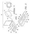
- Fig.2 shows the user interface 27 of the scanner 22 depicted in Fig.1.
- the display device 26 is an LCD (liquid crystal display) which is used for displaying an operation mode of the scanner 22, and also various scanning instructions or image processing instructions received from the computer 14.
- the control panel 28 comprises a plurality of selection keys: four direction keys 30, 32, 34, 36, a start key 42, an ESC (escape) key 40, and an enter key 38.
- a user can select and control an image processing program stored in computer 14 to process the image file of a scanned document by using the selection keys of the control panel 28 according to the instructions displayed over the display device 26.
- Fig.3 is a function block diagram of the image processing system 10 shown in Fig. 1.
- the system 10 comprises a personal computer 14, a monitor 12, a keyboard 18 and a scanner 22.
- the computer 14 comprises a hard disk 66 for storing programs and data, a CPU (central processing unit) 68 for executing programs stored in the hard disk 66, a RAM (random access memory) 70 for storing programs and data for the processor 68, an I/O (input-output) circuit 74 for connecting the floppy disk 16 and keyboard 18, a video circuit 90 which is a VGA (video graphic array) board for performing video processing functions and generating video signals for the monitor 12, a USB (universal serial bus) circuit 64 for communicating with another USB circuit 60 of the scanner 22, and an internal bus 72 for connecting internal components of the computer 14 such as the hard disk 66, CPU 68, RAM 70, I/O circuit 74, video circuit 76, USB circuit 64, etc..
- VGA video graphic array
- the scanner 22 comprises a USB circuit 60, an input circuit 52, a scanning circuit 50, a control circuit 54, a display driver 56 and a display device 26.
- the input circuit 52 is connected to the selection keys of the control panel 28 shown in Fig.2 and is used for generating selection signals according to user inputs.
- the scanning circuit 52 which comprises a step-motor and a charge coupled device (not shown) for scanning documents to generate image signals.
- the control circuit 54 is used for transmitting the image signals generated by the scanning circuit 50 and the selection signals generated by the input circuit 52 to the computer 14, and also for transmitting message signals generated by the computer 14 to the display device 26 through the display driver 56 so that the message signals can be displayed over the display device.
- Fig.4 is a software architecture diagram of the image processing system 10 shown in Fig.1. All the software programs contained in the software architecture are stored in the hard disk 66 and executed by the CPU 58 of the computer 14.
- the software architecture comprises an operating system 80 for controlling various operations of the computer 14, a window interface 81 executed under the operating system 80 for supporting all the programs running under it, a USB driver 84 for controlling operations of the USB circuit 64 which passes USB packets between the computer 14 and the scanner 22, a plurality of image processing programs 86 for processing image signals generated by the scanner 22, and a scanner control program 82 for controlling the scanner 22, sending message signals containing various instructions to the display device 26 of the scanner 22 and distributing signals received from the scanner 22.
- the image processing programs 86 can be any application program which can process the image signals or data generated by the scanner 22 such as OCR (optical character recognition) software, graphic software, file organizer, facsimile software, etc..
- the scanner control program 82 is designed as a platform which comprises a message file (not shown) for storing selection instructions of the image processing programs.
- One or more message signals can be formed by the scanner control program 82 according to the image file and sent to the display device 26 for assisting a user to select an image processing program 86.
- the user then enters his/her selection by using the selection keys of the control panel 28 according to the instruction messages displayed over the display device 26.
- the scanner control program 82 then activates an image processing program according to the selection signals generated by the input circuit 52 and transmits the image signals generated by the scanning circuit 50 to the activated image processing program 86 for further processing.
- the scanner control program 84 can also perform a bridge function between the activated image processing program 86 and the scanner 22 so that the activated image processing program 86 can display more instructions or questions over the display device 26 and receive selection signals inputted by the user according to the displayed instructions or questions.
- the activated image processing program 86 transmits one message signal to the display device 26 through the scanner control program 84.
- the scanner control program 84 transmits the selection signals generated by the user according to the displayed message signal to the activated image processing program 86.
- a user can easily select one image processing program 86 to process the image file generated by a document to be scanned. Further instructions can also be provided by the selected image processing program 86 after the program 86 is activated.
- Such design provides a very simple and direct user interface 27 over the scanner 22 which allows a user to finish his/her image processing job directly by using the display device 26 and the selection keys over the control panel 28.
Landscapes
- Engineering & Computer Science (AREA)
- Multimedia (AREA)
- Signal Processing (AREA)
- General Engineering & Computer Science (AREA)
- Human Computer Interaction (AREA)
- Computing Systems (AREA)
- Facsimiles In General (AREA)
Description
- The present invention relates to an image processing system, and more particularly, to an image processing system which provides a user interface over its scanner for selecting an image processing program to process image signals generated by the scanner.
- Personal computer based image processing systems comprise a scanner for scanning documents to generate image signals and a personal computer having a plurality of image processing programs in it for processing the image signals. When using such a system, a user has to initiate a scanner control program first in the computer to control the scanner operations and then scan a document into the computer through the scanner. After an image file has been created by the scanner control program, the user will initiate one or more image processing programs to process the image file one by one. Such process is not very user friendly since a user has to scan and process the document separately. For users who are not familiar with the computer or software, such process is especially awkward since he or she has to directly interact with each software through a complex window interface in order to process the image file generated by the scanner.
- Known in the prior art is a computer system interconnected to a copying machine wherein the image processing performed by the copying machine is controlled based on a command generated by the computer system (see e.g. EP-A-0 624 969).
- With the aforementioned problems in mind, the present invention aims at providing a personal computer based image processing system as defined in claim 1 which contains a user interface over a scanner to select an image processing program stored in the personal computer to process image signals generated by the scanner automatically.
- This is achieved by the present invention as claimed in that the scanner control program of the image processing system automatically displays a selection instruction over the user interface of the scanner about selecting one of the image processing programs stored in the computer and activating the image processing program selected by a user through the user interface to process the image signals.
- Further improvements in this respect are obtained by the features specified in the dependent claims.
- The invention is illustrated by way of example with reference to the accompanying drawings, in which
- Fig.1 is a perspective view of an image processing system according to the present invention,
- Fig.2 shows the user interface of the scanner depicted in Fig.1,
- Fig.3 is a function block diagram of the image processing system shown in Fig.1, and
- Fig.4 is a software architecture diagram of the image processing system shown in Fig.1.
-
- Please refer to Fig.1. Fig.1 is a perspective view of an
image processing system 10 according to the present invention.System 10 comprises apersonal computer 14 having afloppy disk 16, amonitor 12 for displaying video images generated by thecomputer 14, akeyboard 18 for inputting data to thecomputer 14, and ascanner 22 connected to thecomputer 14 for scanning documents. Thescanner 22 comprises atransparent platform 24 for placing a document to be scanned, auser interface 27 which comprises adisplay device 26 for displaying message signals and acontrol panel 28 having a plurality of selection keys for receiving user inputs. - Please refer to Fig.2. Fig.2 shows the
user interface 27 of thescanner 22 depicted in Fig.1. Thedisplay device 26 is an LCD (liquid crystal display) which is used for displaying an operation mode of thescanner 22, and also various scanning instructions or image processing instructions received from thecomputer 14. Thecontrol panel 28 comprises a plurality of selection keys: fourdirection keys start key 42, an ESC (escape)key 40, and anenter key 38. A user can select and control an image processing program stored incomputer 14 to process the image file of a scanned document by using the selection keys of thecontrol panel 28 according to the instructions displayed over thedisplay device 26. - Please refer to Fig.3. Fig.3 is a function block diagram of the
image processing system 10 shown in Fig. 1. Thesystem 10 comprises apersonal computer 14, amonitor 12, akeyboard 18 and ascanner 22. Thecomputer 14 comprises ahard disk 66 for storing programs and data, a CPU (central processing unit) 68 for executing programs stored in thehard disk 66, a RAM (random access memory) 70 for storing programs and data for theprocessor 68, an I/O (input-output)circuit 74 for connecting thefloppy disk 16 andkeyboard 18, avideo circuit 90 which is a VGA (video graphic array) board for performing video processing functions and generating video signals for themonitor 12, a USB (universal serial bus)circuit 64 for communicating with anotherUSB circuit 60 of thescanner 22, and aninternal bus 72 for connecting internal components of thecomputer 14 such as thehard disk 66,CPU 68,RAM 70, I/O circuit 74, video circuit 76,USB circuit 64, etc.. - The
scanner 22 comprises aUSB circuit 60, aninput circuit 52, ascanning circuit 50, acontrol circuit 54, adisplay driver 56 and adisplay device 26. Theinput circuit 52 is connected to the selection keys of thecontrol panel 28 shown in Fig.2 and is used for generating selection signals according to user inputs. Thescanning circuit 52 which comprises a step-motor and a charge coupled device (not shown) for scanning documents to generate image signals. Thecontrol circuit 54 is used for transmitting the image signals generated by thescanning circuit 50 and the selection signals generated by theinput circuit 52 to thecomputer 14, and also for transmitting message signals generated by thecomputer 14 to thedisplay device 26 through thedisplay driver 56 so that the message signals can be displayed over the display device. - Please refer to Fig.4. Fig.4 is a software architecture diagram of the
image processing system 10 shown in Fig.1. All the software programs contained in the software architecture are stored in thehard disk 66 and executed by the CPU 58 of thecomputer 14. The software architecture comprises anoperating system 80 for controlling various operations of thecomputer 14, awindow interface 81 executed under theoperating system 80 for supporting all the programs running under it, aUSB driver 84 for controlling operations of theUSB circuit 64 which passes USB packets between thecomputer 14 and thescanner 22, a plurality ofimage processing programs 86 for processing image signals generated by thescanner 22, and ascanner control program 82 for controlling thescanner 22, sending message signals containing various instructions to thedisplay device 26 of thescanner 22 and distributing signals received from thescanner 22. - The
image processing programs 86 can be any application program which can process the image signals or data generated by thescanner 22 such as OCR (optical character recognition) software, graphic software, file organizer, facsimile software, etc.. Thescanner control program 82 is designed as a platform which comprises a message file (not shown) for storing selection instructions of the image processing programs. One or more message signals can be formed by thescanner control program 82 according to the image file and sent to thedisplay device 26 for assisting a user to select animage processing program 86. The user then enters his/her selection by using the selection keys of thecontrol panel 28 according to the instruction messages displayed over thedisplay device 26. Thescanner control program 82 then activates an image processing program according to the selection signals generated by theinput circuit 52 and transmits the image signals generated by thescanning circuit 50 to the activatedimage processing program 86 for further processing. - The
scanner control program 84 can also perform a bridge function between the activatedimage processing program 86 and thescanner 22 so that the activatedimage processing program 86 can display more instructions or questions over thedisplay device 26 and receive selection signals inputted by the user according to the displayed instructions or questions. When sending an instruction to the user, the activatedimage processing program 86 transmits one message signal to thedisplay device 26 through thescanner control program 84. Thescanner control program 84 then transmits the selection signals generated by the user according to the displayed message signal to the activatedimage processing program 86. - Through the selection instructions displayed over the
display device 26 of thescanner 22, a user can easily select oneimage processing program 86 to process the image file generated by a document to be scanned. Further instructions can also be provided by the selectedimage processing program 86 after theprogram 86 is activated. Such design provides a very simple anddirect user interface 27 over thescanner 22 which allows a user to finish his/her image processing job directly by using thedisplay device 26 and the selection keys over thecontrol panel 28.
Claims (3)
- An image processing system (10) comprising:characterized in that:a. a personal computer (14) having a memory (66) for storing programs (80, 81, 82, 84, 86) and a processor for executing the programs (80, 81, 82, 84, 86) stored in the memory (66);b. a scanner (22) connected to the computer (14) comprising:a) a scanning circuit (50) for scanning a document to generate image signals, andb) a control circuit (54) for transmitting the image signals to the computer (14);c. a plurality of image processing programs (86) stored in the memory (66) for processing the image signals generated by the scanning circuit (50); andd. a scanner control program (82) stored in the memory (66) for controlling operations of the scanner (22);said scanner (22) further comprises a user interface (27) containing a display device (26) for displaying message signals generated by the computer (14) and an input circuit (52) having a plurality of selection keys (30, 32, 34, 36, 38, 40, 42) for generating selection signals according to user inputs wherein the control circuit (54) transmits the selection signals generated by the input circuit (52) to the computer (14) and transmits the message signals generated by the computer (14) to the display device (26); andsaid scanner control program (82) further:a. transmits a message signal to the display device (26) through the control circuit (54), said message signal containing one selection instruction about selecting one of the image processing programs (86) to process the image signals generated by the scanning circuit (50), andb. activates one of the image processing programs (86) to process the image signals according to a selection signal received from the scanner (22) which is generated by a user according to the message signal displayed by the scanner control program (82).
- The image processing system (10) of claim 1 wherein the activated image processing program (86) further transmits one message signal to the display device (26) and then the scanner control program (82) transmits the selection signals generated by the user according to the displayed message signal to the activated image processing program (86).
- The image processing system (10) of claim 1 wherein the scanner control program (82) comprises a message file for storing selection instructions of the image processing programs (86) and said message signal containing one selection instruction about selecting one of the image processing programs (86) is formed by the scanner control program (82) according to the image file.
Priority Applications (2)
| Application Number | Priority Date | Filing Date | Title |
|---|---|---|---|
| DE1997606284 DE69706284T2 (en) | 1997-05-13 | 1997-05-13 | Personal computer based image processing system to control image processing through a scanner user interface |
| EP19970107751 EP0878951B1 (en) | 1997-05-13 | 1997-05-13 | Personal computer based image processing system for controlling image processing through a user interface of a scanner |
Applications Claiming Priority (1)
| Application Number | Priority Date | Filing Date | Title |
|---|---|---|---|
| EP19970107751 EP0878951B1 (en) | 1997-05-13 | 1997-05-13 | Personal computer based image processing system for controlling image processing through a user interface of a scanner |
Publications (2)
| Publication Number | Publication Date |
|---|---|
| EP0878951A1 EP0878951A1 (en) | 1998-11-18 |
| EP0878951B1 true EP0878951B1 (en) | 2001-08-22 |
Family
ID=8226787
Family Applications (1)
| Application Number | Title | Priority Date | Filing Date |
|---|---|---|---|
| EP19970107751 Expired - Lifetime EP0878951B1 (en) | 1997-05-13 | 1997-05-13 | Personal computer based image processing system for controlling image processing through a user interface of a scanner |
Country Status (2)
| Country | Link |
|---|---|
| EP (1) | EP0878951B1 (en) |
| DE (1) | DE69706284T2 (en) |
Families Citing this family (3)
| Publication number | Priority date | Publication date | Assignee | Title |
|---|---|---|---|---|
| EP0831635B1 (en) * | 1996-09-19 | 2004-07-21 | Canon Kabushiki Kaisha | Image reading system and method |
| US7765271B1 (en) | 2000-02-03 | 2010-07-27 | Hyland Software, Inc. | System and method for scanning a document in client/server environment |
| US7506062B2 (en) * | 2001-08-30 | 2009-03-17 | Xerox Corporation | Scanner-initiated network-based image input scanning |
Family Cites Families (2)
| Publication number | Priority date | Publication date | Assignee | Title |
|---|---|---|---|---|
| EP0624969A1 (en) * | 1993-05-12 | 1994-11-17 | Mita Industrial Co. Ltd. | Image formation processing system |
| US5442541A (en) * | 1993-07-23 | 1995-08-15 | Xerox Corporation | Enabling features over common communication channel |
-
1997
- 1997-05-13 EP EP19970107751 patent/EP0878951B1/en not_active Expired - Lifetime
- 1997-05-13 DE DE1997606284 patent/DE69706284T2/en not_active Expired - Lifetime
Also Published As
| Publication number | Publication date |
|---|---|
| DE69706284D1 (en) | 2001-09-27 |
| DE69706284T2 (en) | 2001-12-06 |
| EP0878951A1 (en) | 1998-11-18 |
Similar Documents
| Publication | Publication Date | Title |
|---|---|---|
| US5913072A (en) | Image processing system in which image processing programs stored in a personal computer are selectively executed through user interface of a scanner | |
| CN101098378B (en) | Image forming device and web server providing workflow status of job, and method to provide workflow status of job in image forming device and web server | |
| JPH08129438A (en) | Display device | |
| US5583539A (en) | Item selection signal input apparatus that reduces the processing load of a host computer | |
| US5938740A (en) | Programmable peripheral control device for controlling peripherals of a computer system | |
| EP0878951A1 (en) | Personal computer based image processing system for controlling image processing through a user interface of a scanner | |
| US20030043423A1 (en) | System and method for scanning to a host computer | |
| US6804017B1 (en) | Information processing device with determination feature | |
| CN1093668C (en) | computer image processing system | |
| US6473060B1 (en) | Monitor control device and control method thereof | |
| US6468214B2 (en) | Apparatus for human interfaces of an ultrasonic diagnostic system | |
| US20030117669A1 (en) | Method and apparatus for fast image fetching and processing | |
| TW422949B (en) | Computer image processing system | |
| US20020120670A1 (en) | System and method for communications between computer systems and peripheral devices | |
| US20020051253A1 (en) | Method and apparatus for fast image fetching and processing | |
| JPH05273948A (en) | Document image display device and document image display method | |
| CN1090777C (en) | Programmable Computer Image Processing System | |
| JP2001312343A (en) | Data processing device | |
| KR101236385B1 (en) | Scanning apparatus and control method thereof | |
| JPH0117589B2 (en) | ||
| JPH11194917A (en) | Printing system | |
| JP2001265478A (en) | Data processing device | |
| JP2001216141A (en) | Liquid crystal display personal computer using input button to start application program | |
| JPH05197494A (en) | Touch pannel input device | |
| JPH1185437A (en) | Information display processing device |
Legal Events
| Date | Code | Title | Description |
|---|---|---|---|
| PUAI | Public reference made under article 153(3) epc to a published international application that has entered the european phase |
Free format text: ORIGINAL CODE: 0009012 |
|
| 17P | Request for examination filed |
Effective date: 19971128 |
|
| AK | Designated contracting states |
Kind code of ref document: A1 Designated state(s): DE FR GB IT |
|
| AKX | Designation fees paid |
Free format text: DE FR GB IT |
|
| GRAG | Despatch of communication of intention to grant |
Free format text: ORIGINAL CODE: EPIDOS AGRA |
|
| GRAG | Despatch of communication of intention to grant |
Free format text: ORIGINAL CODE: EPIDOS AGRA |
|
| GRAG | Despatch of communication of intention to grant |
Free format text: ORIGINAL CODE: EPIDOS AGRA |
|
| GRAH | Despatch of communication of intention to grant a patent |
Free format text: ORIGINAL CODE: EPIDOS IGRA |
|
| 17Q | First examination report despatched |
Effective date: 20000914 |
|
| ITF | It: translation for a ep patent filed | ||
| GRAH | Despatch of communication of intention to grant a patent |
Free format text: ORIGINAL CODE: EPIDOS IGRA |
|
| GRAA | (expected) grant |
Free format text: ORIGINAL CODE: 0009210 |
|
| AK | Designated contracting states |
Kind code of ref document: B1 Designated state(s): DE FR GB IT |
|
| REF | Corresponds to: |
Ref document number: 69706284 Country of ref document: DE Date of ref document: 20010927 |
|
| ET | Fr: translation filed | ||
| REG | Reference to a national code |
Ref country code: GB Ref legal event code: IF02 |
|
| PLBE | No opposition filed within time limit |
Free format text: ORIGINAL CODE: 0009261 |
|
| STAA | Information on the status of an ep patent application or granted ep patent |
Free format text: STATUS: NO OPPOSITION FILED WITHIN TIME LIMIT |
|
| 26N | No opposition filed | ||
| REG | Reference to a national code |
Ref country code: GB Ref legal event code: 732E |
|
| REG | Reference to a national code |
Ref country code: FR Ref legal event code: TP |
|
| PGFP | Annual fee paid to national office [announced via postgrant information from national office to epo] |
Ref country code: IT Payment date: 20080528 Year of fee payment: 12 |
|
| PG25 | Lapsed in a contracting state [announced via postgrant information from national office to epo] |
Ref country code: IT Free format text: LAPSE BECAUSE OF NON-PAYMENT OF DUE FEES Effective date: 20090513 |
|
| REG | Reference to a national code |
Ref country code: FR Ref legal event code: PLFP Year of fee payment: 20 |
|
| PGFP | Annual fee paid to national office [announced via postgrant information from national office to epo] |
Ref country code: GB Payment date: 20160426 Year of fee payment: 20 Ref country code: DE Payment date: 20160524 Year of fee payment: 20 |
|
| PGFP | Annual fee paid to national office [announced via postgrant information from national office to epo] |
Ref country code: FR Payment date: 20160428 Year of fee payment: 20 |
|
| REG | Reference to a national code |
Ref country code: DE Ref legal event code: R071 Ref document number: 69706284 Country of ref document: DE |
|
| REG | Reference to a national code |
Ref country code: GB Ref legal event code: PE20 Expiry date: 20170512 |
|
| PG25 | Lapsed in a contracting state [announced via postgrant information from national office to epo] |
Ref country code: GB Free format text: LAPSE BECAUSE OF EXPIRATION OF PROTECTION Effective date: 20170512 |