EP0878292B1 - Polymeric integral net - Google Patents
Polymeric integral net Download PDFInfo
- Publication number
- EP0878292B1 EP0878292B1 EP19980303470 EP98303470A EP0878292B1 EP 0878292 B1 EP0878292 B1 EP 0878292B1 EP 19980303470 EP19980303470 EP 19980303470 EP 98303470 A EP98303470 A EP 98303470A EP 0878292 B1 EP0878292 B1 EP 0878292B1
- Authority
- EP
- European Patent Office
- Prior art keywords
- net
- billet
- embossed
- lattice
- polymeric material
- Prior art date
- Legal status (The legal status is an assumption and is not a legal conclusion. Google has not performed a legal analysis and makes no representation as to the accuracy of the status listed.)
- Expired - Lifetime
Links
- 238000004049 embossing Methods 0.000 claims description 83
- 238000000034 method Methods 0.000 claims description 68
- 239000000463 material Substances 0.000 claims description 67
- 238000007373 indentation Methods 0.000 claims description 45
- 230000008569 process Effects 0.000 claims description 17
- 239000012530 fluid Substances 0.000 claims description 15
- 238000001914 filtration Methods 0.000 claims description 13
- 229920001343 polytetrafluoroethylene Polymers 0.000 claims description 10
- 239000004810 polytetrafluoroethylene Substances 0.000 claims description 10
- -1 polytetrafluoroethylene Polymers 0.000 claims description 8
- 239000012466 permeate Substances 0.000 claims description 7
- RTZKZFJDLAIYFH-UHFFFAOYSA-N Diethyl ether Chemical compound CCOCC RTZKZFJDLAIYFH-UHFFFAOYSA-N 0.000 claims description 6
- 229920002313 fluoropolymer Polymers 0.000 claims description 6
- 239000004811 fluoropolymer Substances 0.000 claims description 6
- 238000004519 manufacturing process Methods 0.000 claims description 6
- 239000004699 Ultra-high molecular weight polyethylene Substances 0.000 claims description 5
- 239000002356 single layer Substances 0.000 claims description 5
- 229920000785 ultra high molecular weight polyethylene Polymers 0.000 claims description 5
- 239000013618 particulate matter Substances 0.000 claims description 3
- 238000010438 heat treatment Methods 0.000 claims description 2
- 238000009877 rendering Methods 0.000 claims description 2
- 239000012815 thermoplastic material Substances 0.000 claims 3
- 229920000642 polymer Polymers 0.000 description 16
- 239000011148 porous material Substances 0.000 description 9
- 230000001788 irregular Effects 0.000 description 7
- 239000002184 metal Substances 0.000 description 7
- 229910052751 metal Inorganic materials 0.000 description 7
- 239000000047 product Substances 0.000 description 7
- 230000035515 penetration Effects 0.000 description 6
- 239000000945 filler Substances 0.000 description 5
- 239000010410 layer Substances 0.000 description 5
- 239000004813 Perfluoroalkoxy alkane Substances 0.000 description 4
- 239000000835 fiber Substances 0.000 description 4
- 239000000203 mixture Substances 0.000 description 4
- 239000002245 particle Substances 0.000 description 4
- 229920011301 perfluoro alkoxyl alkane Polymers 0.000 description 4
- 239000000126 substance Substances 0.000 description 4
- 229910003460 diamond Inorganic materials 0.000 description 3
- 239000010432 diamond Substances 0.000 description 3
- 230000004048 modification Effects 0.000 description 3
- 238000012986 modification Methods 0.000 description 3
- 238000000926 separation method Methods 0.000 description 3
- 239000005977 Ethylene Substances 0.000 description 2
- 239000002033 PVDF binder Substances 0.000 description 2
- 239000011248 coating agent Substances 0.000 description 2
- 238000000576 coating method Methods 0.000 description 2
- RKTYLMNFRDHKIL-UHFFFAOYSA-N copper;5,10,15,20-tetraphenylporphyrin-22,24-diide Chemical compound [Cu+2].C1=CC(C(=C2C=CC([N-]2)=C(C=2C=CC=CC=2)C=2C=CC(N=2)=C(C=2C=CC=CC=2)C2=CC=C3[N-]2)C=2C=CC=CC=2)=NC1=C3C1=CC=CC=C1 RKTYLMNFRDHKIL-UHFFFAOYSA-N 0.000 description 2
- 238000001125 extrusion Methods 0.000 description 2
- 239000000706 filtrate Substances 0.000 description 2
- 230000002209 hydrophobic effect Effects 0.000 description 2
- 238000002386 leaching Methods 0.000 description 2
- 150000002739 metals Chemical class 0.000 description 2
- 229920002493 poly(chlorotrifluoroethylene) Polymers 0.000 description 2
- 239000005023 polychlorotrifluoroethylene (PCTFE) polymer Substances 0.000 description 2
- 229920002620 polyvinyl fluoride Polymers 0.000 description 2
- 229920002981 polyvinylidene fluoride Polymers 0.000 description 2
- 229920005989 resin Polymers 0.000 description 2
- 239000011347 resin Substances 0.000 description 2
- BFKJFAAPBSQJPD-UHFFFAOYSA-N tetrafluoroethene Chemical group FC(F)=C(F)F BFKJFAAPBSQJPD-UHFFFAOYSA-N 0.000 description 2
- 229920001169 thermoplastic Polymers 0.000 description 2
- BQCIDUSAKPWEOX-UHFFFAOYSA-N 1,1-Difluoroethene Chemical compound FC(F)=C BQCIDUSAKPWEOX-UHFFFAOYSA-N 0.000 description 1
- OKTJSMMVPCPJKN-UHFFFAOYSA-N Carbon Chemical compound [C] OKTJSMMVPCPJKN-UHFFFAOYSA-N 0.000 description 1
- 229920010741 Ultra High Molecular Weight Polyethylene (UHMWPE) Polymers 0.000 description 1
- 239000000853 adhesive Substances 0.000 description 1
- 230000001070 adhesive effect Effects 0.000 description 1
- 230000002411 adverse Effects 0.000 description 1
- 229910052799 carbon Inorganic materials 0.000 description 1
- 230000008859 change Effects 0.000 description 1
- 239000003795 chemical substances by application Substances 0.000 description 1
- 238000000748 compression moulding Methods 0.000 description 1
- 239000000356 contaminant Substances 0.000 description 1
- 229920001577 copolymer Polymers 0.000 description 1
- 238000009295 crossflow filtration Methods 0.000 description 1
- 230000007423 decrease Effects 0.000 description 1
- 238000006073 displacement reaction Methods 0.000 description 1
- 230000002708 enhancing effect Effects 0.000 description 1
- 238000005530 etching Methods 0.000 description 1
- 230000001747 exhibiting effect Effects 0.000 description 1
- 239000012765 fibrous filler Substances 0.000 description 1
- 239000011521 glass Substances 0.000 description 1
- 230000009477 glass transition Effects 0.000 description 1
- 239000004434 industrial solvent Substances 0.000 description 1
- 238000009413 insulation Methods 0.000 description 1
- 238000009940 knitting Methods 0.000 description 1
- 239000012633 leachable Substances 0.000 description 1
- 239000007937 lozenge Substances 0.000 description 1
- 239000012764 mineral filler Substances 0.000 description 1
- 238000004806 packaging method and process Methods 0.000 description 1
- 238000001259 photo etching Methods 0.000 description 1
- 230000002035 prolonged effect Effects 0.000 description 1
- 238000004080 punching Methods 0.000 description 1
- 238000002407 reforming Methods 0.000 description 1
- 238000005245 sintering Methods 0.000 description 1
- 239000007787 solid Substances 0.000 description 1
- 239000003356 suture material Substances 0.000 description 1
- 238000000108 ultra-filtration Methods 0.000 description 1
- 238000011144 upstream manufacturing Methods 0.000 description 1
- 238000010792 warming Methods 0.000 description 1
- 238000005406 washing Methods 0.000 description 1
- 238000009941 weaving Methods 0.000 description 1
Images



Classifications
-
- B—PERFORMING OPERATIONS; TRANSPORTING
- B31—MAKING ARTICLES OF PAPER, CARDBOARD OR MATERIAL WORKED IN A MANNER ANALOGOUS TO PAPER; WORKING PAPER, CARDBOARD OR MATERIAL WORKED IN A MANNER ANALOGOUS TO PAPER
- B31F—MECHANICAL WORKING OR DEFORMATION OF PAPER, CARDBOARD OR MATERIAL WORKED IN A MANNER ANALOGOUS TO PAPER
- B31F1/00—Mechanical deformation without removing material, e.g. in combination with laminating
- B31F1/07—Embossing, i.e. producing impressions formed by locally deep-drawing, e.g. using rolls provided with complementary profiles
-
- B—PERFORMING OPERATIONS; TRANSPORTING
- B01—PHYSICAL OR CHEMICAL PROCESSES OR APPARATUS IN GENERAL
- B01D—SEPARATION
- B01D39/00—Filtering material for liquid or gaseous fluids
- B01D39/14—Other self-supporting filtering material ; Other filtering material
-
- B—PERFORMING OPERATIONS; TRANSPORTING
- B01—PHYSICAL OR CHEMICAL PROCESSES OR APPARATUS IN GENERAL
- B01D—SEPARATION
- B01D67/00—Processes specially adapted for manufacturing semi-permeable membranes for separation processes or apparatus
- B01D67/0002—Organic membrane manufacture
- B01D67/0023—Organic membrane manufacture by inducing porosity into non porous precursor membranes
- B01D67/0025—Organic membrane manufacture by inducing porosity into non porous precursor membranes by mechanical treatment, e.g. pore-stretching
-
- B—PERFORMING OPERATIONS; TRANSPORTING
- B01—PHYSICAL OR CHEMICAL PROCESSES OR APPARATUS IN GENERAL
- B01D—SEPARATION
- B01D69/00—Semi-permeable membranes for separation processes or apparatus characterised by their form, structure or properties; Manufacturing processes specially adapted therefor
- B01D69/10—Supported membranes; Membrane supports
- B01D69/107—Organic support material
- B01D69/1071—Woven, non-woven or net mesh
-
- B—PERFORMING OPERATIONS; TRANSPORTING
- B26—HAND CUTTING TOOLS; CUTTING; SEVERING
- B26D—CUTTING; DETAILS COMMON TO MACHINES FOR PERFORATING, PUNCHING, CUTTING-OUT, STAMPING-OUT OR SEVERING
- B26D3/00—Cutting work characterised by the nature of the cut made; Apparatus therefor
- B26D3/28—Splitting layers from work; Mutually separating layers by cutting
-
- B—PERFORMING OPERATIONS; TRANSPORTING
- B29—WORKING OF PLASTICS; WORKING OF SUBSTANCES IN A PLASTIC STATE IN GENERAL
- B29C—SHAPING OR JOINING OF PLASTICS; SHAPING OF MATERIAL IN A PLASTIC STATE, NOT OTHERWISE PROVIDED FOR; AFTER-TREATMENT OF THE SHAPED PRODUCTS, e.g. REPAIRING
- B29C48/00—Extrusion moulding, i.e. expressing the moulding material through a die or nozzle which imparts the desired form; Apparatus therefor
- B29C48/03—Extrusion moulding, i.e. expressing the moulding material through a die or nozzle which imparts the desired form; Apparatus therefor characterised by the shape of the extruded material at extrusion
- B29C48/07—Flat, e.g. panels
- B29C48/08—Flat, e.g. panels flexible, e.g. films
-
- B—PERFORMING OPERATIONS; TRANSPORTING
- B29—WORKING OF PLASTICS; WORKING OF SUBSTANCES IN A PLASTIC STATE IN GENERAL
- B29C—SHAPING OR JOINING OF PLASTICS; SHAPING OF MATERIAL IN A PLASTIC STATE, NOT OTHERWISE PROVIDED FOR; AFTER-TREATMENT OF THE SHAPED PRODUCTS, e.g. REPAIRING
- B29C69/00—Combinations of shaping techniques not provided for in a single one of main groups B29C39/00 - B29C67/00, e.g. associations of moulding and joining techniques; Apparatus therefore
- B29C69/001—Combinations of shaping techniques not provided for in a single one of main groups B29C39/00 - B29C67/00, e.g. associations of moulding and joining techniques; Apparatus therefore a shaping technique combined with cutting, e.g. in parts or slices combined with rearranging and joining the cut parts
-
- B—PERFORMING OPERATIONS; TRANSPORTING
- B29—WORKING OF PLASTICS; WORKING OF SUBSTANCES IN A PLASTIC STATE IN GENERAL
- B29D—PRODUCING PARTICULAR ARTICLES FROM PLASTICS OR FROM SUBSTANCES IN A PLASTIC STATE
- B29D7/00—Producing flat articles, e.g. films or sheets
- B29D7/01—Films or sheets
-
- B—PERFORMING OPERATIONS; TRANSPORTING
- B01—PHYSICAL OR CHEMICAL PROCESSES OR APPARATUS IN GENERAL
- B01D—SEPARATION
- B01D2323/00—Details relating to membrane preparation
- B01D2323/42—Details of membrane preparation apparatus
-
- B—PERFORMING OPERATIONS; TRANSPORTING
- B29—WORKING OF PLASTICS; WORKING OF SUBSTANCES IN A PLASTIC STATE IN GENERAL
- B29C—SHAPING OR JOINING OF PLASTICS; SHAPING OF MATERIAL IN A PLASTIC STATE, NOT OTHERWISE PROVIDED FOR; AFTER-TREATMENT OF THE SHAPED PRODUCTS, e.g. REPAIRING
- B29C48/00—Extrusion moulding, i.e. expressing the moulding material through a die or nozzle which imparts the desired form; Apparatus therefor
- B29C48/001—Combinations of extrusion moulding with other shaping operations
-
- B—PERFORMING OPERATIONS; TRANSPORTING
- B29—WORKING OF PLASTICS; WORKING OF SUBSTANCES IN A PLASTIC STATE IN GENERAL
- B29C—SHAPING OR JOINING OF PLASTICS; SHAPING OF MATERIAL IN A PLASTIC STATE, NOT OTHERWISE PROVIDED FOR; AFTER-TREATMENT OF THE SHAPED PRODUCTS, e.g. REPAIRING
- B29C48/00—Extrusion moulding, i.e. expressing the moulding material through a die or nozzle which imparts the desired form; Apparatus therefor
- B29C48/03—Extrusion moulding, i.e. expressing the moulding material through a die or nozzle which imparts the desired form; Apparatus therefor characterised by the shape of the extruded material at extrusion
- B29C48/12—Articles with an irregular circumference when viewed in cross-section, e.g. window profiles
-
- B—PERFORMING OPERATIONS; TRANSPORTING
- B29—WORKING OF PLASTICS; WORKING OF SUBSTANCES IN A PLASTIC STATE IN GENERAL
- B29C—SHAPING OR JOINING OF PLASTICS; SHAPING OF MATERIAL IN A PLASTIC STATE, NOT OTHERWISE PROVIDED FOR; AFTER-TREATMENT OF THE SHAPED PRODUCTS, e.g. REPAIRING
- B29C48/00—Extrusion moulding, i.e. expressing the moulding material through a die or nozzle which imparts the desired form; Apparatus therefor
- B29C48/03—Extrusion moulding, i.e. expressing the moulding material through a die or nozzle which imparts the desired form; Apparatus therefor characterised by the shape of the extruded material at extrusion
- B29C48/13—Articles with a cross-section varying in the longitudinal direction, e.g. corrugated pipes
-
- B—PERFORMING OPERATIONS; TRANSPORTING
- B31—MAKING ARTICLES OF PAPER, CARDBOARD OR MATERIAL WORKED IN A MANNER ANALOGOUS TO PAPER; WORKING PAPER, CARDBOARD OR MATERIAL WORKED IN A MANNER ANALOGOUS TO PAPER
- B31F—MECHANICAL WORKING OR DEFORMATION OF PAPER, CARDBOARD OR MATERIAL WORKED IN A MANNER ANALOGOUS TO PAPER
- B31F2201/00—Mechanical deformation of paper or cardboard without removing material
- B31F2201/07—Embossing
- B31F2201/0707—Embossing by tools working continuously
- B31F2201/0715—The tools being rollers
-
- B—PERFORMING OPERATIONS; TRANSPORTING
- B31—MAKING ARTICLES OF PAPER, CARDBOARD OR MATERIAL WORKED IN A MANNER ANALOGOUS TO PAPER; WORKING PAPER, CARDBOARD OR MATERIAL WORKED IN A MANNER ANALOGOUS TO PAPER
- B31F—MECHANICAL WORKING OR DEFORMATION OF PAPER, CARDBOARD OR MATERIAL WORKED IN A MANNER ANALOGOUS TO PAPER
- B31F2201/00—Mechanical deformation of paper or cardboard without removing material
- B31F2201/07—Embossing
- B31F2201/0707—Embossing by tools working continuously
- B31F2201/0715—The tools being rollers
- B31F2201/0723—Characteristics of the rollers
- B31F2201/0733—Pattern
-
- B—PERFORMING OPERATIONS; TRANSPORTING
- B31—MAKING ARTICLES OF PAPER, CARDBOARD OR MATERIAL WORKED IN A MANNER ANALOGOUS TO PAPER; WORKING PAPER, CARDBOARD OR MATERIAL WORKED IN A MANNER ANALOGOUS TO PAPER
- B31F—MECHANICAL WORKING OR DEFORMATION OF PAPER, CARDBOARD OR MATERIAL WORKED IN A MANNER ANALOGOUS TO PAPER
- B31F2201/00—Mechanical deformation of paper or cardboard without removing material
- B31F2201/07—Embossing
- B31F2201/0707—Embossing by tools working continuously
- B31F2201/0715—The tools being rollers
- B31F2201/0723—Characteristics of the rollers
- B31F2201/0738—Cross sectional profile of the embossments
-
- B—PERFORMING OPERATIONS; TRANSPORTING
- B31—MAKING ARTICLES OF PAPER, CARDBOARD OR MATERIAL WORKED IN A MANNER ANALOGOUS TO PAPER; WORKING PAPER, CARDBOARD OR MATERIAL WORKED IN A MANNER ANALOGOUS TO PAPER
- B31F—MECHANICAL WORKING OR DEFORMATION OF PAPER, CARDBOARD OR MATERIAL WORKED IN A MANNER ANALOGOUS TO PAPER
- B31F2201/00—Mechanical deformation of paper or cardboard without removing material
- B31F2201/07—Embossing
- B31F2201/0707—Embossing by tools working continuously
- B31F2201/0715—The tools being rollers
- B31F2201/0741—Roller cooperating with a non-even counter roller
- B31F2201/0743—Roller cooperating with a non-even counter roller having a matching profile
-
- B—PERFORMING OPERATIONS; TRANSPORTING
- B31—MAKING ARTICLES OF PAPER, CARDBOARD OR MATERIAL WORKED IN A MANNER ANALOGOUS TO PAPER; WORKING PAPER, CARDBOARD OR MATERIAL WORKED IN A MANNER ANALOGOUS TO PAPER
- B31F—MECHANICAL WORKING OR DEFORMATION OF PAPER, CARDBOARD OR MATERIAL WORKED IN A MANNER ANALOGOUS TO PAPER
- B31F2201/00—Mechanical deformation of paper or cardboard without removing material
- B31F2201/07—Embossing
- B31F2201/0707—Embossing by tools working continuously
- B31F2201/0754—The tools being other than rollers, e.g. belts or plates
-
- B—PERFORMING OPERATIONS; TRANSPORTING
- B31—MAKING ARTICLES OF PAPER, CARDBOARD OR MATERIAL WORKED IN A MANNER ANALOGOUS TO PAPER; WORKING PAPER, CARDBOARD OR MATERIAL WORKED IN A MANNER ANALOGOUS TO PAPER
- B31F—MECHANICAL WORKING OR DEFORMATION OF PAPER, CARDBOARD OR MATERIAL WORKED IN A MANNER ANALOGOUS TO PAPER
- B31F2201/00—Mechanical deformation of paper or cardboard without removing material
- B31F2201/07—Embossing
- B31F2201/0756—Characteristics of the incoming material, e.g. creped, embossed, corrugated
-
- B—PERFORMING OPERATIONS; TRANSPORTING
- B31—MAKING ARTICLES OF PAPER, CARDBOARD OR MATERIAL WORKED IN A MANNER ANALOGOUS TO PAPER; WORKING PAPER, CARDBOARD OR MATERIAL WORKED IN A MANNER ANALOGOUS TO PAPER
- B31F—MECHANICAL WORKING OR DEFORMATION OF PAPER, CARDBOARD OR MATERIAL WORKED IN A MANNER ANALOGOUS TO PAPER
- B31F2201/00—Mechanical deformation of paper or cardboard without removing material
- B31F2201/07—Embossing
- B31F2201/0784—Auxiliary operations
- B31F2201/0797—Perforating
-
- Y—GENERAL TAGGING OF NEW TECHNOLOGICAL DEVELOPMENTS; GENERAL TAGGING OF CROSS-SECTIONAL TECHNOLOGIES SPANNING OVER SEVERAL SECTIONS OF THE IPC; TECHNICAL SUBJECTS COVERED BY FORMER USPC CROSS-REFERENCE ART COLLECTIONS [XRACs] AND DIGESTS
- Y10—TECHNICAL SUBJECTS COVERED BY FORMER USPC
- Y10T—TECHNICAL SUBJECTS COVERED BY FORMER US CLASSIFICATION
- Y10T428/00—Stock material or miscellaneous articles
- Y10T428/24—Structurally defined web or sheet [e.g., overall dimension, etc.]
- Y10T428/24273—Structurally defined web or sheet [e.g., overall dimension, etc.] including aperture
-
- Y—GENERAL TAGGING OF NEW TECHNOLOGICAL DEVELOPMENTS; GENERAL TAGGING OF CROSS-SECTIONAL TECHNOLOGIES SPANNING OVER SEVERAL SECTIONS OF THE IPC; TECHNICAL SUBJECTS COVERED BY FORMER USPC CROSS-REFERENCE ART COLLECTIONS [XRACs] AND DIGESTS
- Y10—TECHNICAL SUBJECTS COVERED BY FORMER USPC
- Y10T—TECHNICAL SUBJECTS COVERED BY FORMER US CLASSIFICATION
- Y10T428/00—Stock material or miscellaneous articles
- Y10T428/24—Structurally defined web or sheet [e.g., overall dimension, etc.]
- Y10T428/24273—Structurally defined web or sheet [e.g., overall dimension, etc.] including aperture
- Y10T428/24298—Noncircular aperture [e.g., slit, diamond, rectangular, etc.]
-
- Y—GENERAL TAGGING OF NEW TECHNOLOGICAL DEVELOPMENTS; GENERAL TAGGING OF CROSS-SECTIONAL TECHNOLOGIES SPANNING OVER SEVERAL SECTIONS OF THE IPC; TECHNICAL SUBJECTS COVERED BY FORMER USPC CROSS-REFERENCE ART COLLECTIONS [XRACs] AND DIGESTS
- Y10—TECHNICAL SUBJECTS COVERED BY FORMER USPC
- Y10T—TECHNICAL SUBJECTS COVERED BY FORMER US CLASSIFICATION
- Y10T428/00—Stock material or miscellaneous articles
- Y10T428/249921—Web or sheet containing structurally defined element or component
- Y10T428/249953—Composite having voids in a component [e.g., porous, cellular, etc.]
-
- Y—GENERAL TAGGING OF NEW TECHNOLOGICAL DEVELOPMENTS; GENERAL TAGGING OF CROSS-SECTIONAL TECHNOLOGIES SPANNING OVER SEVERAL SECTIONS OF THE IPC; TECHNICAL SUBJECTS COVERED BY FORMER USPC CROSS-REFERENCE ART COLLECTIONS [XRACs] AND DIGESTS
- Y10—TECHNICAL SUBJECTS COVERED BY FORMER USPC
- Y10T—TECHNICAL SUBJECTS COVERED BY FORMER US CLASSIFICATION
- Y10T428/00—Stock material or miscellaneous articles
- Y10T428/249921—Web or sheet containing structurally defined element or component
- Y10T428/249953—Composite having voids in a component [e.g., porous, cellular, etc.]
- Y10T428/249978—Voids specified as micro
-
- Y—GENERAL TAGGING OF NEW TECHNOLOGICAL DEVELOPMENTS; GENERAL TAGGING OF CROSS-SECTIONAL TECHNOLOGIES SPANNING OVER SEVERAL SECTIONS OF THE IPC; TECHNICAL SUBJECTS COVERED BY FORMER USPC CROSS-REFERENCE ART COLLECTIONS [XRACs] AND DIGESTS
- Y10—TECHNICAL SUBJECTS COVERED BY FORMER USPC
- Y10T—TECHNICAL SUBJECTS COVERED BY FORMER US CLASSIFICATION
- Y10T442/00—Fabric [woven, knitted, or nonwoven textile or cloth, etc.]
- Y10T442/10—Scrim [e.g., open net or mesh, gauze, loose or open weave or knit, etc.]
- Y10T442/184—Nonwoven scrim
Landscapes
- Engineering & Computer Science (AREA)
- Mechanical Engineering (AREA)
- Chemical & Material Sciences (AREA)
- Chemical Kinetics & Catalysis (AREA)
- Life Sciences & Earth Sciences (AREA)
- Forests & Forestry (AREA)
- Manufacturing & Machinery (AREA)
- Shaping Of Tube Ends By Bending Or Straightening (AREA)
Description
- The present invention relates to an integral net of polymeric material and a method for producing the same.
- Polymeric nets or webs are sheet-like fenestrate structures comprising polymeric material. Polymeric nets find utility in a variety of disparate applications ranging from electronics to medical care, and such nets are thus commercially important materials. These nets can have different qualities depending upon their mode of engineering. For example, such nets can be fashioned from a variety of polymers, have a variety of hole sizes and shapes, and can assume almost any desired thickness.
- In many applications, it is desirable to have nets fashioned from relatively inert matter in order to avoid compromising the integrity of the net lattice or affecting materials in contact with the net. Polymers represent attractive choices for nets to be employed in these applications, as many polymers are extremely resistant to most chemicals. In fact, fluoropolymers such as polytetrafluoroethylene (PTFE) rank as some of the most chemically inert materials. Thus, nets of fluoropolymers would be highly useful in applications in which the nets are exposed to harsh conditions, such as in batteries, filtration apparatuses, and the like.
- In other applications, it is desirable to fashion nets to include a minimal amount of extractable material, as such matter can affect the physical and chemical properties of the polymeric lattice, and hence the net, as well as contaminate materials in contact with the net. Nets comprising reactive extractable material are changed or degraded over time as the extractable material is removed from the net. Perhaps more importantly, in other applications, such as filtration devices in which nets are employed as filter media or as support elements, the presence of extractable matter in the net lattice adversely affects the ultimate quality of the filtrate. Notably, extractable matter can be- leached from the net lattice, thus contaminating the filtrate and/or filtered material.
- GB 1,331,775 to Imperial Chemical Industries Limited discloses a process for the manufacture of a porous tetrafluoroethylene polymer tape comprising, compression moulding a cylindrical billet from a mixture of tetrafluoroethylene polymer particles and particles of fibrous leachable filler, sintering the billet, skiving a tape from the circumference of the billet, and leaching out at least some of the fibrous filler particles from the tape and washing the tape to remove residual leaching agent.
- It is also often desirable to have extremely thin polymeric nets and nets with very small, regularly shaped holes or pores. Such nets are useful in filtration devices, especially ultrafiltration devices, for removing very small particles (e.g., microbes) from a fluid. Furthermore, very thin nets minimize the pressure differential across a filter during filtration, thus enhancing the efficiency of some types of filtration (e.g., dynamic or crossflow filtration).
- Typically, many types of polymeric nets are manufactured by extrusion, by weaving, by knitting, or by punching holes or slits into a sheet of polymeric material. It is very difficult and costly to control the size and shape of holes or pores in nets produced by many of these processes, especially where very small and uniform holes are required and for very thin nets. Moreover, many commonly employed processes for fabricating nets, especially extrusion, are prone to introduce a significant amount of extractable matter (e.g., metals, resins, etc.) into the polymer lattice.
- Thus, there exists a need for a net substantially free of extractable matter and a very thin net having substantially uniform hole size and shape. The present invention provides such a polymeric net, as well as a method of preparing same. These and other advantages of the present invention, as well as additional inventive features, will be apparent from the description of the invention provided herein.
- According to a first aspect of the invention, a nonwoven, nonextruded, single-layer integral net comprises an embossed lattice of polymeric material, having two opposing faces and a plurality of holes traversing the net from one face to the other face wherein the lattice is substantially free of extractable matter.
- According to a second aspect of the invention, a method for producing an embossed lattice comprises contacting a billet of polymeric material with an embossing tool having a plurality of protrusions to provide an embossed billet, and skiving the embossed billet to provide a nonwoven, nonextruded, single-layer integral net comprising an embossed lattice.
- The present invention is useful in applications utilizing nets or fibers, such as in medical devices or products, gas exchange or oxygenator devices, electronic devices, in separation applications, or other applications allowing for the use of polymeric nets or fibers.
- The invention is best understood with reference to the accompanying drawings and in the following detailed description of the preferred embodiments.
- Figures 1A-1C are schematic representations of the surfaces of polymeric integral nets of the present invention. Figure 1B is a magnified schematic representation of the holes and lattice of one type of integral net depicted in Figure 1A, and Figure 1C is a similar magnified schematic representation of the holes and lattice of an alternative type of integral net.
- Figure 2 is a schematic representation of a cylindrical billet of polymeric material with a rotary spur-type embossing tool and a blade for skiving an embossed sheet from the billet.
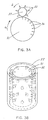
- Figures 3A-3G are schematic representations of various types of polymeric billets with embossing tools. Figure 3A is a schematic side view representation of a cylindrical billet of polymeric material and a rotary spur-type embossing tool and the impressions made by the embossing tool into the surface of the billet. Figure 3B is a schematic representation of a cylindrical billet of polymeric material with a sheath-type embossing tool. Figure 3C is an end view depicting a cylindrical billet of polymeric material within a sheath-type embossing tool. Figure 3D is schematic representation of a planar billet of polymeric material with a press-type embossing tool. Figure 3E is a cross-sectional side view of Figure 3D depicting a planar billet of polymeric material with a press-type embossing tool. Figure 3F is schematic representation of a hollow billet of polymeric material with a rotary spur-type embossing tool. Figure 3G is schematic representation of a planar billet of polymeric material with a rotary spur-type embossing tool.
- Figures 4A-4B are schematic side view representations of embossed billets of polymeric material, blades for skiving embossed sheets from the billets, and embossed sheets having an embossed pattern. Figure 4A is a schematic side view representation of a cylindrical billet of polymeric material having impressions made by an embossing tool into the surface of the billet, a blade for skiving an embossed sheet from the billet, and a sheet having an embossed pattern. Figure 4B is a schematic representation of a planar billet of polymeric material having impressions made by an embossing tool into the surface of the billet, a blade for skiving an embossed sheet from the billet, and a sheet having an embossed pattern.
- Figures 5A and 5B are schematic representations of different embodiments of tapered protrusions on an embossing tool. Figure 5A represents a pyramidal protrusion, while Figure 5B represents a conical protrusion.
- Figure 6 is a cross-sectional schematic representation of a portion of a billet, including the billet surface, showing synclinal indentations produced from an embossing tool with tapered protrusions. Dashed lines A, B, and C represent three of many potential planes for skiving the embossed billet.
- Figure 7 is a schematic representation of a surface of an embossed sheet or integral net showing a lattice having punctate depressions or furrows between some adjacent holes.
- The present invention provides a nonwoven, nonextruded, integral reticulate net (such as a single-layer net) having a lattice of polymeric material defined by holes or by pores. As used herein, a net is any fenestrate sheet having holes traversing the sheet from one surface to the other. Preferably, the integral net is non-extruded in order to minimize the presence of extractable matter (e.g., metals, resins, and the like) in the net lattice. Also, the net preferably has not been stretched, as stretching can cause variation in lattice structure.
- The net can comprise any suitable polymeric material (e.g., virgin, reprocessed, recycled, etc.). Preferably, the integral net comprises polymeric material, such as thermoplastic polymers, etc., and the polymeric net can include filler material, (e.g., glass fillers, carbon fillers, mineral fillers, or other suitable fillers). In many applications, the integral net comprises polymeric material exhibiting superior chemical resistance and skivability, such as, for example, a fluoropolymer, polytetrafluoroethylene (PTFE), or ultra high molecular weight polyethylene (UHMWPE). Examples of suitable fluoropolymers are polychlorotrifluoroethylene (PCTFE), polychlorotrifluoroethylene-co-ethylene (E/CTFE-polymer), polytetrafluoroethylene-co-hexafluropropylene (FEP), polytetrafluoroethylene-co-perfluoro(alkylvinyl ether) (PFA), polytetrafluoroethylene-co-ethylene (E/TFE), polyvinyl fluoride (PVF), polyvinylidene fluoride (PVDF), and copolymers of vinylidene fluoride. Most preferably, the polymer is either PTFE, PFA or UHMWPE. In addition, regardless of the nature of the polymer, integral nets according to the present invention are preferably substantially free of contaminants (e.g., extractable material), such as integral nets consisting essentially of the polymeric material. For example, the net can comprise less than about 500 part per million (ppm) extractable matter, such as less than about 100 ppm or even 50 ppm extractable matter (e.g., less than about 10 ppm extractable matter), such as less than about 1 ppm extractable matter, and more preferably the net comprises less than about 10 part per billion (ppb) metal extractable matter (e.g., about 1 ppb metal extractable matter). Most preferably, integral nets according to the present invention consist entirely of the desired polymer. Thus, preferred integral nets of the present invention can be practically chemically inert, such that the structural integrity of the integral net lattice is maintained even upon prolonged contact with very strong industrial solvents and wherein substantially no material leaches from the integral net lattice into a fluid in contact with the integral net. However, in other applications (such as for use as surgical products, biodegradable packaging, etc.), the polymeric material is preferably reactive material.
- Polymeric integral nets of the present invention can be constructed by any suitable means. The integral net can be hydrophilic or hydrophobic; the integral net can have smooth or rough surfaces; and the integral net can be coated or conjugated with other materials (e.g., a surface coating).
- Integral nets of the present invention can be of any dimension or form, provided, however, that the integral net is a fenestrate sheet-like structure. Thus, the integral net can be of any desired size, such as several meters in width or length or merely a few centimeters in width or length, or even significantly smaller or larger. Furthermore, the integral net can assume any shape; thus, for example, the integral net can be rectangular, square, round, oval, oblong, polygonal, irregular, or any other desired shape.
- While an integral net of the present invention can be of any suitable dimension, it is a sheet-like structure. Thus, the integral net lattice preferably is thin in comparison with its length and breadth; however, the integral net lattice can have any desired thickness. For example, the lattice can be several micrometers thick, although thicker lattices can be one or several millimeters thick, or even thicker (e.g., a centimeter or more in thickness). Accordingly, the lattice desirably has a thickness of about 1000 µm or less (e.g., about 1-750 µm), preferably about 500 µm or less (e.g., about 10-500 µm), more preferably about 250 µm or less (e.g., about 50-250 µm), and most preferably about 200 µm or less (e.g., about 100-200 µm). Of course, lattices can be significantly thicker or thinner than these exemplified dimensions. Furthermore, lattice thickness can vary or be uniform (e.g., thicker in some places than in others), and variant lattice thickness can be either gradient or irregular. Preferably, however, the lattice is of approximately uniform thickness throughout, and most preferably the lattice is of substantially uniform thickness.
- While the present invention encompasses integral nets having any suitable shape, size, and thickness (provided the integral net is sheet-like), integral nets of the present invention are fenestrate. Thus, an integral net of the present invention has one or more holes or pores traversing its thickness from one surface to the other. An integral net of the present invention can have any suitable number of such holes, but an integral net must have at least one such hole. Preferably, an integral net has an array of holes traversing its thickness, and the array can be either regular or irregular. Moreover, the holes can be of any dimension or size. For example holes can be about a few micrometers wide, or they can be larger, such as about a millimeter wide, or even larger (e.g., about a centimeter or more). Moreover, the integral net can have a plurality of hole sizes, ranging considerably in width. Alternatively, the hole size can be approximately uniform throughout an integral net of the present invention. The exact dimensions for the holes within an integral net of the present invention can vary depending upon the use to which the integral net is to be put. Thus, for example, an integral net having very small holes (e.g., a few micrometers wide) provides an excellent filter for separating particulate matter from a fluid, while an integral net having larger holes (e.g., less than about 1000 µm wide, particularly 500-800 µm wide) provides excellent support means for use in filtration devices. A preferred integral net has tapered holes of approximately uniform shape arrayed into a regular pattern. Preferably, the pattern is arranged in columns and rows such that lattice width surrounding each hole is substantially uniform. An example of such an arrangement is the pattern with diamond openings depicted in Fig. 7.
- An integral net according to the present invention is schematically depicted in Figs. 1A-1C. By virtue of the
holes 11, thepolymeric lattice 13 of the integral net 12 forms a reticular structure. Thus, an integral net 12 preferably comprises apolymeric lattice 13, the structure of which is defined byholes 11 traversing the integral net 12 from one face to the other. Depending upon the placement of theholes 11, thepolymeric lattice 13 can be regularly arrayed (Fig. 1B) or irregularly arrayed (Fig. 1C). Moreover, depending upon the size of theholes 11, thepolymeric lattice 13 can comprise a majority of the area of the integral net area or thepolymeric lattice 13 can comprise a minority of the integral net area. - In addition to having holes and a polymeric lattice, an integral net can have additional elements as well. Thus, integral nets can be surface-treated (e.g., by imparting a hydrophilic or hydrophobic coating to the surface of the integral net) or surface-contoured (e.g., to facilitate fluid dynamics). For example, as depicted in Fig. 7,
integral nets 71 can havepunctate depressions 74 into a surface (or even both opposing surfaces) of itslattice 72. Thedepressions 74 can form furrows or channels betweenadjacent holes 73. However, for other applications, the net surface is preferably smooth. Of course, integral nets can have any of a number of other additional features for facilitating their use in varied applications (e.g., integral nets can be charge modified, coated on one or both surfaces with adhesive, stretched, etc.). - The integral net of the present invention is useful in a variety of applications allowing for the use of polymeric nets or fibers, such as in medical devices or products (e.g., as dressing or suture material), gas exchange or oxygenator devices, electronic devices (e.g., as insulation such as in batteries), in separation applications (e.g., as filters or support means within filtration devices), or other applications. Thus, the present invention provides a filtration apparatus having an integral net of the present invention. The filtration apparatus comprises a housing, a process fluid inlet arranged to direct process fluid into the housing, a permeate outlet arranged to direct permeate from the housing, at least one separation element disposed within the housing and including an integral net according to the present invention, a surface of which (i.e., an upstream surface) communicating with the process fluid inlet, and another surface of which (i.e., a downstream surface) communicating with the permeate outlet. The present invention further provides a method of separating matter (e.g., particulate matter) from a process fluid employing such a filtration apparatus.
- While the integral net can be produced by any suitable method, the present invention provides a preferred method for producing such a net as well as for producing other embossed sheets (e.g., non-fenestrate sheets). In accordance with the present inventive method, and as schematically depicted in Fig. 2, the
embossed sheet 26 is produced from abillet 21. The method preferably makes use of an embossing tool 22 (preferably havingprotrusions 23, to produce one ormore indentations 24 in the billet 21) and ablade 25 for skiving (i.e., slicing thebillet 21 tangentially) to produce anembossed sheet 26. - As depicted in Figs. 4A-B, by this method a patterned
embossed sheet 42 of the polymeric material is removed from thebillet 41, theembossed sheet 42 having two surfaces 49a, 49b and theembossed pattern 44. - As used herein, including the claims appended hereto, a billet is any block, ingot, or other mass suitable for embossing and subsequent skiving, regardless of its shape or composition. The billet can be formed by any suitable means, such as, for example, by being molded or by other desired means for forming polymeric billets. Most preferably, the billet is formed by a method that greatly minimizes or substantially eliminates the presence of extractable matter. Thus, a preferred billet for use in the present inventive method is an essentially pure mass of the desired polymeric material, such as a billet consisting essentially of the desired polymer, or even a billet consisting entirely of the desired polymer. For example, the billet can comprise less than about 500 parts per million (ppm) extractable matter, such as less than about 100 ppm or even 50 ppm extractable matter (e.g., less than about 10 ppm extractable matter), such as less than about 1 ppm extractable matter, and more preferably the billet comprises less than about 10 part per billion (ppb) metal extractable matter (e.g., less than about 1 ppb metal extractable matter). Of course, the precise means for forming the billet will depend largely upon the nature of the polymeric material, and such means are well known in the art. The billet can comprise any suitable polymeric material (e.g., virgin, reprocessed, recycled, etc.), such as those materials described elsewhere herein. Preferred polymeric materials are those which are readily skived, and the polymeric material also desirably is sufficiently deformable to enable a billet of the polymeric material to be embossed with a suitable device. Most preferably, the billet consists essentially of PTFE, PFA, or UHMWPE.
- A billet of polymeric material for use in the present inventive method can have any suitable shape or dimensions. For example, as depicted in Fig. 2, a
billet 21 can be a cylinder. Such abillet 21 can be solid or recessed for positioning on amandrel 27. In other embodiments, abillet 31 can be hollow (Fig. 3F) or planar (Figs. 3D-3E). Moreover, billets can have any other desired surface characteristic (i.e., contoured, concave, convex, etc.). Moreover, where a billet is planar, it can be of any desired shape. For example, the surface of a planar billet can be square, round, oval, oblong, polygonal, etc., or even irregular. - As depicted in Figs. 3A-3G, the present inventive method involves first embossing the
billet 31 such thatindentations 34 are introduced into a surface of thebillet 31 to a given depth. Any means of embossing thebillet 31 is within the scope of the present inventive method. Thus, thebillet 31 can haveindentations 34 formed by separately impressingindentations 34 into the billet 31 (i.e. reforming the surface of the billet 31), such as with a punch, one or more embossing tools, or other suitable means or device. Alternatively, theindentations 34 can be formed by removing material from thebillet 31, (such as with a drill or other device, by photo etching, by chemically etching, or via other suitable treatment). Preferably, thebillet 31 is embossed by using anembossing tool 33. - The
embossing tool 33 for use in the present inventive method can be of any type suitable for impressingindentations 34 into the billet. The type of embossing tool depends upon a variety of parameters, such as the surface contours of thebillet 31, the type of polymer, and the desired qualities of the polymeric embossed sheet products. One example of asuitable embossing tool 33 is a die (e.g., a metal die) having a plurality ofprotrusions 32. As depicted in Figs. 3A, 3F, and 3G, someembossing tools 33 for use in the present inventive method are rotary spur-type embossing tools 33 which are rotated axially to bringsuccessive protrusions 32 into contact with the surface of thebillet 31. As depicted in Figs. 3B-3C, another type ofembossing tool 33 is a sheath-type embossing tool 33 with inwardly projectingradial protrusions 32. As depicted in Figs. 3D and 3E, another type ofembossing tool 33 is a press-type embossing tool 33 withprotrusions 32 projecting from one surface. In addition to the depicted embossing tools, other types of embossing tools can be used within the scope of the present inventive method. - Embossing can be accomplished by any suitable technique, and the choice of embossing technique is controlled to a large extent by the characteristics of the
billet 31 and theembossing tool 33. For example, a billet can be embossed by passing a rotary spur-type embossing tool 33 along thebillet 31 tangentially to the surface of the billet 31 (Figs. 3A and 3G). Alternatively, abillet 31 can be embossed by placing thebillet 31 within a sheath-type embossing tool 33 (Figs. 3B-3C), by contacting abillet 31 with a press-type embossing tool 33 (Figs. 3D-3E), by embossing the inner surface of a hollow billet (Fig. 3F), or by other suitable means. As depicted in Fig. 3A, acylindrical billet 31 is efficiently embossed while it is axially rotated (such as in the direction indicated by arrow a) relative to a rotary spur-type embossing tool 33 axially rotated in the opposite direction (such as in the direction indicated by arrow b). Regardless of the technique for embossing, however, the process of embossing introducesindentations 34 into a surface of thebillet 31 as herein described. - An
embossing tool 33 preferably hasprotrusions 32 for contacting thebillet 31.Protrusions 32 can form any desired array (e.g., a pattern or irregular array) on theembossing tool 33.Protrusions 32 can be spaced regularly or irregularly, and an array ofprotrusions 32 can be of any desired density (e.g., from about 1/cm2 to about 500/cm2, typically about 10/cm2 to about 100/cm2). Where theembossing tool 33 is a rotary spur-type embossing tool 33, theprotrusions 32 can form an irregular or linear array along the length of theembossing tool 32; alternatively, theprotrusions 32 can form a helical array of any desired degree (helices of about 5°-75°, such as about 15°-60°, or even about 30°-45°, are typical). For example, a rotary spur-type embossing tool for forming an embossed sheet having the pattern with diamond openings as depicted in Fig. 7, has protrusions arranged in about a 45° spiral angle wherein opposite sides of the projections have an about 90° included angle (i.e. angle as indicated in Fig. 5A is about 45°). By varying the placement of theprotrusions 32, the present inventive method can produce embossed sheets of varying qualities. - The
protrusions 32 also can be of any suitable dimension for impressingindentations 34 into thebillet 31. As the impression or hole size of a polymeric sheet is related to the width of the embossing tool protrusions 32 (as well as to the depth of the protrusion penetration), the exact dimensions of theprotrusions 32 will vary depending upon the desired qualities of the polymeric embossed sheet product. Thus, for producing an embossed sheet having very small impressions or holes (e.g., a polymeric integral net capable of fine filtration), theprotrusions 32 can have a maximal width at the level of penetration of less than about 20 µm; for example, aprotrusion 32 can be less than about 10 µm (e.g., less than about 5 µm) wide at the level of penetration. It is within the scope of the present inventive method to employembossing tools 33 with evensmaller protrusions 32 to produce polymeric embossed sheets with small impressions (such as integral nets with very small holes or pores). Similarly,embossing tools 33 for producing embossed sheets or integral nets with larger impressions or holes will haveprotrusions 32 larger than this relatively small size (i.e., width at the level of penetration of about 20 µm wide or larger). For example, in many applications,protrusions 32 are up to about a millimeter wide at the level of penetration, while in other applications,protrusions 32 are up to about a centimeter wide at the level of penetration. It will be understood thatprotrusions 32 can be even significantly wider than these exemplified dimensions depending upon the desired properties of the polymeric embossed sheet product. - The height of the
protrusions 32 limits the maximal depth of theindentations 34 into thebillet 31; thus,longer protrusions 32 can embossdeeper indentations 34 than can shorter ones. Of course, theprotrusions 32 need not be inserted to their full length into the billet 31 (i.e., alonger protrusion 32 can still emboss a relatively shallow indentation 34). Thus,protrusions 32 can be of any suitable height to produceindentations 34 of a desired depth. Depending upon the depth at which the embossedbillet 31 is skived,deeper indentations 34 permit several layers of polymeric embossed sheet to be produced from abillet 31 which has been embossed only once. Furthermore, where the desired embossed sheet is an integral net,deeper indentations 34 permit thicker nets to be skived. Thus, in many applications, aprotrusion 32 is relatively high in order to facilitate the removal of as much product as practicable from abillet 31 embossed once. Conversely, in other applications (e.g., in order to save thebillet 31 for subsequent embossing with a different pattern of indentations 34), theprotrusions 32 are shorter, and in many applications,protrusions 32 are so short as to penetrate thebillet 31 only slightly. Moreover, anembossing tool 33 can haveprotrusions 32 of varying heights in order to produceindentations 34 of varying depths in thebillet 31. -
Protrusions 32 can be of any desired cross-sectional shape; thus,protrusions 32 can be tetragonal (e.g., rhomboids, rectangles, lozenges, etc.), round, ovoid, oblong, orthogonal, stelliform, or any other desired shape. Furthermore,embossing tools 33 can haveprotrusions 32 of uniform shape or of varied shape. Moreover, aprotrusion 32 can change shape along its length (e.g., tetragonal at the base and round at the tip, or other suitable arrangement) in order to produceindentations 34 of varying shape. Thus, abillet 31, once embossed, can be successively skived to produce embossed sheets of varying qualities. Alternatively, theprotrusions 32 can be such to impress groove-like indentations in the billet such that subsequent skiving will produce filaments (e.g., fibers), rather than an integral net with a lattice. - While the
protrusions 32 can have any desired shape, they are preferably tapered. As depicted schematically in Figs. 5A-5B, taperedprotrusions 52 are either pyramidal (Fig. 5A) or conical (Fig. 5B). Most preferably, theprotrusions 52 for forming the pattern with diamond openings depicted in Fig 7 are pyramidal in shape. The taper can be outward or, preferably, inward from the base of the protrusion and can be of any degree , such as, for example, less than about 90° (i.e., included angle of less than about 180°), such as less than about 60° (i.e., included angle of less than about 120°), such as less than about 45° (i.e., included angle of less than about 90°), less than about 30° (i.e., included angle of less than about 60°), or even less than 15° (i.e., included angle of less than about 30°). Indeed, the taperedprotrusions 52 can form pins having a very slight taper, e.g., of less than about 5° (i.e., an included angle of less than about 10°) and need not be tapered at all. However, preferably theprotrusions 52 of theembossing tool 51 are uniformly tapered, and more preferably the projections have a 90° included angle (i.e., inward taper is about 45°). It will be observed in Figs. 5A, 5B and 6 that where theprotrusions 52 are tapered, theindentations 62 produced by theprotrusions 52 are accordingly synclinal. - Because protrusions need not be inserted to their maximal depth into the billet during the embossing step, embossing tools having tapered protrusions are preferred because they afford a greater measure of control over the resulting embossed sheet. For example, by setting the depth into which the protrusions are inserted, the size of the indentations can be controlled. Thus, wider indentations can be embossed by inserting the protrusions to a greater depth.
- As schematically depicted in Figs. 4A-4B, subsequent to embossing, the present inventive method involves skiving the embossed
billet 41, preferably by severably engaging thebillet 41 with ablade 45. Any means of skiving thebillet 41 is within the scope of the present inventive method. Thus, thebillet 41 can be skived by passing theblade 45 through thebillet 41 tangentially to the surface of thebillet 41. However, the embossedbillet 41 is more evenly skived by moving it relative to astationary blade 45, and this method of skiving the billet is preferred. Thus, as depicted in Fig 4A, a cylindrical billet is most evenly skived while it is axially rotated (as indicated by arrow a) to engage astationary blade 45. Similarly, as depicted in Fig. 4B, aplanar billet 41 is most evenly skived by moving it forward to engage a stationary blade (as indicated by arrow b). - The
billet 41 can be skived at any depth relative to the depth of theimpressed indentations 43. In many applications, thebillet 41 is skived at a depth more shallow than the depth of theimpressed indentations 43. It is thus seen that anembossed sheet 42 which is removed from thebillet 41 by skiving is an integral net (i.e., a fenestrate sheet) because theembossed sheet 42 retains the pattern ofindentations billet 41 by previously embossing thebillet 41. In other applications, thebillet 41 is skived at a depth exceeding the depth of theimpressed indentations 43, producing anembossed sheet 42 that is not fenestrate but is thinner at the sites of theimpressed indentations indentations - Skiving can be accomplished by any suitable technique, and the choice of skiving techniques is controlled to a large extent by the characteristics of the embossed
billet 41. For example, as illustrated in Fig. 6, after being once embossed, abillet 61 withindentations 62 can be skived several times, for example at successive depths (e.g., dashed lines A, B, and C), to produce integral nets with different hole sizes (lines A and B) or non-fenestrate embossed sheets (line C). Also, as depicted in Fig. 4A, acylindrical billet 41 once embossed can be skived in a spiral (e.g., a concentric spiral) to produce a singleembossed sheet 42 from the billet. Moreover, as depicted in Fig. 2, acylindrical billet 21 can be continuously embossed with a rotary spur-type embossing tool 22 and skived while it is rotated axially (such as indicated by arrow a) relative to ablade 25. Because the billet's diameter decreases as layers of embossedsheet 26 are spirally skived from thebillet 21, theblade 25 can be continuously indexed against thebillet 21, or thebillet 21 can be continuously indexed towards theblade 25, to maintain a desired depth of skiving. Moreover, in order to maintain uniform pattern definition following skiving off of layers of embossed sheet, theembossing tool 22 can be continuously indexed against thebillet 21, or thebillet 21 can be continuously indexed towards the embossingtool 22. Thus, a continuous integral net with substantially uniform hole sizes can be produced from acylindrical billet 21 of polymeric material. - As mentioned herein, the present inventive method preferably employs tapered embossing tool protrusions to impress synclinal indentations into the billet. As illustrated in Fig. 6, integral nets with pores or holes of varying dimensions can be produced from
embossed billets 61 havingsynclinal indentations 62 by varying the depth at which the embossedbillet 61 is subsequently skived (dashed lines A and B). For example, skiving an embossedbillet 61 havingsynclinal indentations 62 at a relatively shallow depth (line A in Fig. 6) produces an integral net having relatively wider holes or pores and narrower lattice, while skiving thebillet 61 at a deeper level (line B in Fig. 6) produces an integral net having relatively smaller holes or pores and wider lattice. Thus, according to the present inventive method, several separate integral nets, each with distinct hole sizes but each having the same pattern and spacing of pores or holes, can be produced from the sameembossed billet 61 havingsynclinal indentations 62 by repeated skiving of thebillet 61 at successively greater depths (lines A and B). Skiving thebillet 61 at a level deeper than the depth of the indentations 62 (line C in Fig. 6) produces a non-fenestrate sheet. It should be noted that where the billet, once embossed, is to be skived successively, the hole size of successive layers skived from a billet with synclinal indentations will necessarily be narrower. As such, if uniformity in hole size as between successive layers is desired, either the billet must be re-embossed over the existing pattern prior to each successive skiving, or the protrusions of the embossing tool should not be tapered. - By controlling the processes of embossing and skiving the billet, an embossed sheet with a lattice of any suitable thickness can be produced, as previously described. For example, control over the embossing step can affect the lattice thickness. Displacement of billet material by the protrusions causes the surface of the billet to swell, as the total volume of the billet is not significantly altered during the embossing step. Thus, varying the dimensions of the embossing tool protrusions as well as the embossing depth affects the degree to which the billet is distended by the embossing step. Furthermore, by controlling the skiving process, the present inventive method can produce embossed sheets of variable lattice thickness or of uniform lattice thickness. Variable depth skiving can produce an embossed sheet lattice which is thicker in some places than in others, with the variations being either gradient or irregular. Furthermore, the shape of the blade (e.g., serrated, or otherwise non-uniform) can affect the thickness of the embossed sheet or net lattice. Of course, by controlling the skiving process, the present inventive method can produce embossed sheet lattices having approximately uniform thickness throughout, and even lattices having substantially uniform thickness.
- In addition to the aforementioned steps of first embossing and subsequently skiving the polymeric billet, the present inventive method can include other steps as well. For example, the present inventive method can involve pretreating the billet of polymeric material in a suitable manner. The nature of the desired pretreatment will depend to a large extent upon the composition of the polymer, and such pretreatment is within the skill of the art. For example, the billet, or any portion thereof, can be heated prior to, or during, the embossing step so as to render the polymeric material more conducive to indentation during the embossing step. For example, the billet can be heated to a uniform temperature in an oven prior to embossing. Alternatively, the embossing tool can comprise a heating element for warming a surface of the billet during the embossing step. The temperature to which the billet is heated will depend upon the polymer. For thermoplastic polymers, the surface of the billet is heated to near the glass transition temperature. A PTFE billet preferably is heated to temperature above room temperature (e.g., above about 25 °C) up to about 185 °C, more preferably from about 135 °C to about 165 °C (e.g., about 150 °C). Similarly, the surface of a billet comprising UHMWPE preferably is heated to a temperature above room temperature up to about 60 °C, more preferably from about 50 °C to about 60 °C (e.g., about 55 °C) whereas the surface of a billet comprising PFA preferably is heated to a temperature above room temperature up to about 185 °C, more preferably from about 135 °C to about 165 °C (e.g., about 150 °C).
- The embossed sheet of polymeric material can be modified following skiving from the embossed billet. The nature of the desired modifications will depend to a large extent upon the composition of the polymer and the intended application for the embossed sheet. Such modifications are within the skill of the art. Thus, for example, one or both surfaces of the embossed sheet can be smoothed, heat-treated, annealed, coated, etc. Furthermore, embossed sheets produced by skiving the billet at a depth exceeding the depth of the indentations can be stretched subsequent to skiving in order to rupture the thin portions at the regions of the impressed indentations, thereby rendering them fenestrate (i.e., integral nets). Of course, the embossed sheet of polymeric material can be modified in any other suitable fashion.
- In some applications, the present inventive method further comprises contacting the integral net with a second embossing device (or even two or more embossing devices, blades, serrated edges, etc.) such that, as illustrated in Fig. 7,
punctate depressions 74 orfurrows 74 are imprinted into a surface of theembossed sheet lattice 72 between some adjacent holes orindentations 73. Thefurrows 74 ordepressions 74 need not be between every adjacent hole. In some applications, it may be desirable that thefurrows 74 break through thelattice 72 so as to form fissures between some of the adjacent holes orindentations 73. - While the discussion herein has indicated means by which a billet can be embossed, the present inventive method need not employ the first step of embossing. In some applications, for example, a billet of polymeric material already may comprise a suitable array of indentations, such as those indentations described herein. Of course, such billets need not be further embossed for use in the present inventive method. In such embodiments, thus, the present invention provides a method for producing an embossed sheet from an embossed billet of polymeric material (i.e., a billet having a surface with one or more indentations deep to the surface of the billet) by skiving the embossed billet as described herein. By this method, an embossed sheet of polymeric material is removed from the billet.
- The present method can produce polymeric embossed sheets substantially free from extractable matter. This is possible because the embossed sheet is produced without employing manipulations known to create or introduce extractable matter associated with the embossed sheet. Although the billet is contacted with the embossing tool and skiving blade as herein described, such manipulation at most introduces contaminating matter only at the surface of the embossed sheet, which matter is not integrated into the embossed sheet. Subsequently, the skived embossed sheet can be bathed or washed in a suitable fluid to remove any trace material deposits from the surface of the embossed sheet.
- All of the references cited herein, including patents, patent applications, and publications, are hereby incorporated in their entireties by reference.
- While this invention has been described with an emphasis upon preferred embodiments, it will be obvious to those of ordinary skill in the art that variations of the preferred embodiments can be used and that it is intended that the invention can be practiced otherwise than as specifically described herein. Accordingly, this invention includes all modifications encompassed within the scope of the invention as defined by the following claims.
Claims (25)
- A nonwoven, nonextruded, single-layer integral net (12,71) comprising an embossed lattice (13,26,42) of polymeric material, having two opposing faces and a plurality of holes (11,73) traversing the net from one face to the other face wherein the lattice is substantially free of extractable matter.
- The net of claim 1, wherein the polymeric material is thermoplastic material.
- The net of claim 2, wherein the thermoplastic material is a fluoropolymer.
- The net of claim 1, wherein the polymeric material is polytetrafluoroethylene co-perfluoro (alkylvinyl ether).
- The net of claim 1, wherein the polymeric material is ultra high molecular weight polyethylene.
- The net of claim 1, wherein the polymeric material is polytetrafluoroethylene.
- The net of any one of claims 1 to 6, which consists essentially of the polymeric material.
- The net of any one of claims 1 to 8, wherein a face of the lattice comprises punctate depressions (74) into a surface of the lattice.
- The net of claim 8, wherein a depression forms a furrow between two adjacent holes of the net.
- The net of any one of claims 1 to 9, wherein the lattice has not been stretched.
- The net of any one of claims 1 to 10, wherein the width of the holes is about 20 micrometers or greater.
- The net of any one of claims 1-11, disposed within a filtration apparatus, the filtration apparatus comprising a housing, a process fluid inlet, and a permeate outlet, wherein the process fluid inlet is arranged to direct process fluid into the housing and the permeate outlet is arranged to direct permeate from the housing and wherein one surface of the net communicates with the process fluid inlet and another surface of the net communicates with the permeate outlet.
- A method of separating particulate matter from a process fluid comprising passing the process fluid through the net of any one of claims 1 to 11.
- A method for producing an embossed lattice (13,26,42) comprising:contacting a billet (21,31,41,61) of polymeric material with an embossing tool (22,33,51) having a plurality of protrusions (23,32,52) to provide an embossed billet; andskiving the embossed billet to provide a nonwoven,nonextruded, single-layer integral net (12,71) comprising an embossed lattice.
- The method of claim 14, wherein the polymeric material is polytetrafluoroethylene-co-perfluoro (alkylvinyl ether), ultra high molecular weight polyethylene, or polytetrafluoroethylene.
- The method of claim 14, wherein the polymeric material comprises a thermoplastic material.
- The method of claim 14, wherein the polymeric material comprises a fluoropolymer.
- The method of any one of claims 14 to 17 wherein the billet consists essentially of the polymeric material.
- The method of any one of claims 14 to 18, wherein the method further comprises heat-treating the embossed lattice of the polymeric material.
- The method of any one of claims 14 to 19, wherein the method further comprises rendering hydrophilic a surface of the embossed lattice.
- The method of any one of claims 14 to 20, wherein the method further comprises contacting the embossed lattice with a second embossing tool, whereby punctate depressions (74) are imprinted into a surface of the embossed lattice.
- The method of claim 21, wherein the punctate depressions are furrows between two adjacent indentations (24,34,43,62) of the embossed lattice.
- The method of any one of claims 14 to 22, which method further comprises heating the surface of the billet prior to contacting the billet with the embossing tool.
- The method of any one of claims 14 to 23, wherein the embossed lattice has not been stretched.
- The method of any one of claims 14 to 24, wherein the embossed lattice is substantially free of extractable matter.
Applications Claiming Priority (2)
| Application Number | Priority Date | Filing Date | Title |
|---|---|---|---|
| US08/858,082 US6277464B1 (en) | 1997-05-16 | 1997-05-16 | Polymeric integral net |
| US858082 | 1997-05-16 |
Publications (2)
| Publication Number | Publication Date |
|---|---|
| EP0878292A1 EP0878292A1 (en) | 1998-11-18 |
| EP0878292B1 true EP0878292B1 (en) | 2003-04-16 |
Family
ID=25327435
Family Applications (1)
| Application Number | Title | Priority Date | Filing Date |
|---|---|---|---|
| EP19980303470 Expired - Lifetime EP0878292B1 (en) | 1997-05-16 | 1998-05-01 | Polymeric integral net |
Country Status (7)
| Country | Link |
|---|---|
| US (2) | US6277464B1 (en) |
| EP (1) | EP0878292B1 (en) |
| JP (1) | JP3372870B2 (en) |
| KR (1) | KR19980087053A (en) |
| CA (1) | CA2236705A1 (en) |
| DE (1) | DE69813367T2 (en) |
| SG (1) | SG63842A1 (en) |
Families Citing this family (21)
| Publication number | Priority date | Publication date | Assignee | Title |
|---|---|---|---|---|
| US6277464B1 (en) * | 1997-05-16 | 2001-08-21 | Pall Corporation | Polymeric integral net |
| US6703461B1 (en) * | 1998-03-25 | 2004-03-09 | Daikin Industries, Ltd. | Method of reducing metal content in fluoroelastomer |
| JP4001418B2 (en) * | 1998-06-15 | 2007-10-31 | 旭硝子株式会社 | Fluorine-containing copolymer molding material |
| JP4683735B2 (en) * | 2001-01-26 | 2011-05-18 | 株式会社クレハ | Vinylidene fluoride polymer and method for producing the same |
| KR100454196B1 (en) * | 2001-08-27 | 2004-10-26 | 이성호 | The method of preparing filter paper coated by cross stripes with hot melt resin's compassion for package of medicine tool |
| EP1308255A1 (en) * | 2001-10-30 | 2003-05-07 | Dsm N.V. | Process for the manufacturing of a shaped part of ultra high molecular weight polyethylene and a fibre made with this process |
| SE0200590D0 (en) * | 2002-02-26 | 2002-02-26 | Sca Hygiene Prod Ab | Method and device for producing a multi-ply web of flexible material, such as paper and nonwoven, and multi-ply material produced the method |
| US20030215602A1 (en) * | 2002-02-26 | 2003-11-20 | Anders Andersson | Method and device for producing a multi-ply web of flexible material, such as paper and nonwoven, and multi-ply material and product produced by the method |
| US6749997B2 (en) * | 2002-05-14 | 2004-06-15 | Sandia National Laboratories | Method for providing an arbitrary three-dimensional microstructure in silicon using an anisotropic deep etch |
| US20040250683A1 (en) * | 2002-10-18 | 2004-12-16 | Innovative Construction And Building Materials, Llc | Advanced filtration devices and methods |
| CA2413467A1 (en) * | 2002-11-29 | 2004-05-29 | Ian Glenn Towe | Spacer for electrically driven membrane process apparatus |
| US20070125756A1 (en) * | 2003-02-10 | 2007-06-07 | Kelly William G | Method of making topographical support members for producing apertured films |
| AT501770B1 (en) * | 2005-04-07 | 2007-10-15 | Michel Wolfgang Ing | METHOD FOR PRODUCING A PROFILED TRAIL FROM POLYTETRAFLUOROETHYLENE |
| DE102006023889A1 (en) * | 2006-05-15 | 2007-11-22 | Elringklinger Ag | Device for the production of a molded foil from a raw material containing fluoropolymer material, comprises a cutting blade with a edge contour corresponding to the required shaping |
| US8545439B2 (en) * | 2009-03-10 | 2013-10-01 | Dongguan Kidsme Industrial Limited | Feeding apparatus |
| EP2511085B1 (en) * | 2011-04-11 | 2018-02-28 | Tenax S.p.A. | A product having a net structure |
| WO2012170928A1 (en) * | 2011-06-10 | 2012-12-13 | Crocs, Inc. | Molded footwear with woven appearance and ventilation features |
| JP4878660B1 (en) * | 2011-09-12 | 2012-02-15 | 株式会社アクト | Method for producing long material having embossed pattern |
| ES2704246T3 (en) | 2014-08-06 | 2019-03-15 | Swm Luxembourg Sarl | Fluoroplast support sheet with grooves and ribbed for a filter substrate and method to perform the same |
| CN105458082B (en) * | 2014-08-21 | 2019-10-15 | 福特环球技术公司 | Forming openings method, stamping die and vehicle trim panel on panel |
| KR102371013B1 (en) * | 2017-09-11 | 2022-03-04 | 현대자동차주식회사 | The fabrication method of bubble sheet for vehicle |
Family Cites Families (25)
| Publication number | Priority date | Publication date | Assignee | Title |
|---|---|---|---|---|
| NL136829C (en) | 1964-11-20 | |||
| GB1106254A (en) | 1965-05-31 | 1968-03-13 | Smith & Nephew | Improvements in and relating to the production of nets from thermoplastic sheets or films |
| GB1128977A (en) | 1965-12-16 | 1968-10-02 | Stafford Tool & Die Company Lt | A press for embossing and perforating flexible materials |
| GB1331775A (en) | 1970-07-09 | 1973-09-26 | Ici Ltd | Porous tetrafluoroethylene polymer tape |
| US3922329A (en) | 1973-01-16 | 1975-11-25 | Hercules Inc | Methods of making network structures |
| US4226828A (en) | 1978-12-20 | 1980-10-07 | Hercules Incorporated | Process for producing a reticulated web net |
| EP0062462B1 (en) | 1981-04-03 | 1986-10-22 | P.L.G. Research Limited | Plastics material mesh structure |
| US4474721A (en) * | 1983-02-28 | 1984-10-02 | Chemplast, Inc. | Apparatus for forming threads and filaments of fluorocarbon resin and method thereof |
| US4647416A (en) | 1983-08-03 | 1987-03-03 | Shiley Incorporated | Method of preparing a vascular graft prosthesis |
| JPH0635151B2 (en) * | 1986-02-06 | 1994-05-11 | 宇部興産株式会社 | Manufacturing method of polyimide sheet molding |
| GB8613015D0 (en) | 1986-05-29 | 1986-07-02 | Thomas T R | Porous ptfe |
| US4876051A (en) | 1986-11-13 | 1989-10-24 | W. L. Gore & Associates, Inc. | Apparatus and method for extruding and expanding polytetrafluoroethylene tubing and the products produced thereby |
| JPS63273651A (en) * | 1987-04-30 | 1988-11-10 | Toa Nenryo Kogyo Kk | Production of fine porous membrane of polyolefin having ultra-high molecular weight |
| JPS63283857A (en) * | 1987-05-15 | 1988-11-21 | Asahi Chem Ind Co Ltd | Polishing cloth |
| US4978486A (en) | 1987-08-20 | 1990-12-18 | Mitsui Toatsu Chemicals, Incorporated | Method for preparing perforated film |
| US4964992A (en) * | 1989-03-21 | 1990-10-23 | Goldsmith Susan H | Method of making membrane-type filter and product thereof |
| JPH06104736B2 (en) * | 1989-08-03 | 1994-12-21 | 東燃株式会社 | Polyolefin microporous membrane |
| JPH0371826A (en) * | 1989-08-11 | 1991-03-27 | Mitsui Petrochem Ind Ltd | Perforated sheet and molding thereof |
| JPH0823033B2 (en) | 1992-01-17 | 1996-03-06 | 大同メタル工業株式会社 | Composite sliding member |
| JPH06311A (en) * | 1992-06-22 | 1994-01-11 | Japan Gore Tex Inc | Filtering material |
| DE69327973T2 (en) * | 1993-02-18 | 2000-10-19 | W.L. Gore & Associates, Inc. | MACROSCOPIC PERFORATED POROUS MATERIAL MADE OF POLYTETRAFLUORETHYLENE |
| US5693273A (en) * | 1995-09-11 | 1997-12-02 | Redound Industries, Inc. | Method of making multi-porosity porous plastic strips |
| EP0970799B2 (en) * | 1997-03-19 | 2010-09-08 | Daikin Industries, Ltd. | method of production of a molded polytetrafluoroethylene article |
| US6524681B1 (en) * | 1997-04-08 | 2003-02-25 | 3M Innovative Properties Company | Patterned surface friction materials, clutch plate members and methods of making and using same |
| US6277464B1 (en) * | 1997-05-16 | 2001-08-21 | Pall Corporation | Polymeric integral net |
-
1997
- 1997-05-16 US US08/858,082 patent/US6277464B1/en not_active Expired - Lifetime
-
1998
- 1998-04-28 SG SG1998000880A patent/SG63842A1/en unknown
- 1998-05-01 DE DE1998613367 patent/DE69813367T2/en not_active Expired - Lifetime
- 1998-05-01 EP EP19980303470 patent/EP0878292B1/en not_active Expired - Lifetime
- 1998-05-05 CA CA 2236705 patent/CA2236705A1/en not_active Abandoned
- 1998-05-14 KR KR1019980017418A patent/KR19980087053A/en not_active Abandoned
- 1998-05-18 JP JP17376898A patent/JP3372870B2/en not_active Expired - Lifetime
-
2001
- 2001-05-25 US US09/864,154 patent/US20010024710A1/en not_active Abandoned
Also Published As
| Publication number | Publication date |
|---|---|
| US6277464B1 (en) | 2001-08-21 |
| SG63842A1 (en) | 1999-03-30 |
| JP3372870B2 (en) | 2003-02-04 |
| DE69813367T2 (en) | 2004-03-04 |
| JPH11105133A (en) | 1999-04-20 |
| EP0878292A1 (en) | 1998-11-18 |
| US20010024710A1 (en) | 2001-09-27 |
| KR19980087053A (en) | 1998-12-05 |
| CA2236705A1 (en) | 1998-11-16 |
| DE69813367D1 (en) | 2003-05-22 |
Similar Documents
| Publication | Publication Date | Title |
|---|---|---|
| US6277464B1 (en) | Polymeric integral net | |
| EP0726841B1 (en) | Macroscopically perforated porous polytetrafluoroethylene materials | |
| TWI506070B (en) | Microperforated polymeric film and methods of making and using the same | |
| EP0301599B1 (en) | Apertured film and net like fabrics from thermoplastic materials | |
| CN1109146C (en) | Method and device for producing structured voluminous non-woven web of film | |
| EP1578223B1 (en) | Heat treated high density structures | |
| US4226828A (en) | Process for producing a reticulated web net | |
| US20040126531A1 (en) | Method for the treating films | |
| HUE034208T2 (en) | Method for making an apertured web | |
| EP3169424B1 (en) | Membrane with performance enhancing multi-level macroscopic cavities | |
| CA2957072C (en) | Ribbed and apertured fluoroplastic support sheet for a filter substrate and method of making same | |
| CN1205269A (en) | Polymeric integral net | |
| JP4471868B2 (en) | Polytetrafluoroethylene fiber and method for producing the same | |
| GB2073097A (en) | Producing a reticulated web | |
| US4289464A (en) | Reticulated web making apparatus | |
| CA1131869A (en) | Reticulated web making process and apparatus | |
| CN109070002A (en) | Separating film element | |
| US20010044008A1 (en) | Serrated screens for forming apertured three-dimensional sheet materials | |
| AU2013273668B2 (en) | Microperforated polymeric film and methods of making and using the same | |
| JPS62227634A (en) | Manufacture of perforated thermoplastic plastic sheet |
Legal Events
| Date | Code | Title | Description |
|---|---|---|---|
| PUAI | Public reference made under article 153(3) epc to a published international application that has entered the european phase |
Free format text: ORIGINAL CODE: 0009012 |
|
| AK | Designated contracting states |
Kind code of ref document: A1 Designated state(s): DE FR GB IT |
|
| AX | Request for extension of the european patent |
Free format text: AL;LT;LV;MK;RO;SI |
|
| 17P | Request for examination filed |
Effective date: 19990225 |
|
| AKX | Designation fees paid |
Free format text: DE FR GB IT |
|
| 17Q | First examination report despatched |
Effective date: 20010628 |
|
| GRAH | Despatch of communication of intention to grant a patent |
Free format text: ORIGINAL CODE: EPIDOS IGRA |
|
| GRAH | Despatch of communication of intention to grant a patent |
Free format text: ORIGINAL CODE: EPIDOS IGRA |
|
| GRAA | (expected) grant |
Free format text: ORIGINAL CODE: 0009210 |
|
| AK | Designated contracting states |
Designated state(s): DE FR GB IT |
|
| REG | Reference to a national code |
Ref country code: GB Ref legal event code: FG4D |
|
| REF | Corresponds to: |
Ref document number: 69813367 Country of ref document: DE Date of ref document: 20030522 Kind code of ref document: P |
|
| ET | Fr: translation filed | ||
| PLBE | No opposition filed within time limit |
Free format text: ORIGINAL CODE: 0009261 |
|
| STAA | Information on the status of an ep patent application or granted ep patent |
Free format text: STATUS: NO OPPOSITION FILED WITHIN TIME LIMIT |
|
| 26N | No opposition filed |
Effective date: 20040119 |
|
| PGFP | Annual fee paid to national office [announced via postgrant information from national office to epo] |
Ref country code: IT Payment date: 20080526 Year of fee payment: 11 |
|
| REG | Reference to a national code |
Ref country code: FR Ref legal event code: ST Effective date: 20100129 |
|
| PG25 | Lapsed in a contracting state [announced via postgrant information from national office to epo] |
Ref country code: FR Free format text: LAPSE BECAUSE OF NON-PAYMENT OF DUE FEES Effective date: 20090602 |
|
| PGFP | Annual fee paid to national office [announced via postgrant information from national office to epo] |
Ref country code: FR Payment date: 20080514 Year of fee payment: 11 |
|
| PG25 | Lapsed in a contracting state [announced via postgrant information from national office to epo] |
Ref country code: IT Free format text: LAPSE BECAUSE OF NON-PAYMENT OF DUE FEES Effective date: 20090501 |
|
| REG | Reference to a national code |
Ref country code: DE Ref legal event code: R082 Ref document number: 69813367 Country of ref document: DE Representative=s name: HOEGER, STELLRECHT & PARTNER PATENTANWAELTE MB, DE |
|
| PGFP | Annual fee paid to national office [announced via postgrant information from national office to epo] |
Ref country code: DE Payment date: 20170530 Year of fee payment: 20 Ref country code: GB Payment date: 20170530 Year of fee payment: 20 |
|
| REG | Reference to a national code |
Ref country code: DE Ref legal event code: R071 Ref document number: 69813367 Country of ref document: DE |
|
| REG | Reference to a national code |
Ref country code: GB Ref legal event code: PE20 Expiry date: 20180430 |
|
| PG25 | Lapsed in a contracting state [announced via postgrant information from national office to epo] |
Ref country code: GB Free format text: LAPSE BECAUSE OF EXPIRATION OF PROTECTION Effective date: 20180430 |