EP0878154A2 - Garment display frame - Google Patents
Garment display frame Download PDFInfo
- Publication number
- EP0878154A2 EP0878154A2 EP98303808A EP98303808A EP0878154A2 EP 0878154 A2 EP0878154 A2 EP 0878154A2 EP 98303808 A EP98303808 A EP 98303808A EP 98303808 A EP98303808 A EP 98303808A EP 0878154 A2 EP0878154 A2 EP 0878154A2
- Authority
- EP
- European Patent Office
- Prior art keywords
- body member
- engaging
- display frame
- garment
- frame according
- Prior art date
- Legal status (The legal status is an assumption and is not a legal conclusion. Google has not performed a legal analysis and makes no representation as to the accuracy of the status listed.)
- Granted
Links
- 239000000463 material Substances 0.000 description 2
- 229920003023 plastic Polymers 0.000 description 2
- 239000004033 plastic Substances 0.000 description 2
- 230000004075 alteration Effects 0.000 description 1
- 238000010276 construction Methods 0.000 description 1
- 238000000034 method Methods 0.000 description 1
- 238000012986 modification Methods 0.000 description 1
- 230000004048 modification Effects 0.000 description 1
Images





Classifications
-
- A—HUMAN NECESSITIES
- A47—FURNITURE; DOMESTIC ARTICLES OR APPLIANCES; COFFEE MILLS; SPICE MILLS; SUCTION CLEANERS IN GENERAL
- A47F—SPECIAL FURNITURE, FITTINGS, OR ACCESSORIES FOR SHOPS, STOREHOUSES, BARS, RESTAURANTS OR THE LIKE; PAYING COUNTERS
- A47F7/00—Show stands, hangers, or shelves, adapted for particular articles or materials
- A47F7/19—Show stands, hangers, or shelves, adapted for particular articles or materials for garments
Definitions
- the present invention relates to a garment display frame, and relates particularly, but not exclusively, to a display frame for knitwear or the like.
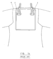
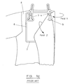
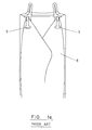
- Knitwear frames are generally known for displaying knitwear such as pullovers in a generally flat, folded arrangement at a point of sale. Such a knitwear frame is shown in Figures 1a to 1f.
- the known knitwear frame consists of a body member 1 of plastics material having a pair of outwardly projecting legs 2 attached to an upper part of the body member 1, and a pair of clamping portions 3 arranged below respective outwardly projecting arms 2.
- Each clamping portion 3 consists of a generally planar loop portion 4 and a sloping clamp member 5 which has two inclined portions.
- a pair of downwardly projecting fold members 6 extend from respective outer ends of the body member 1 and the ends of the fold member 6 remote from the body member are joined by means of a base member 7.
- the knitwear frame is mounted to a pullover 8 by inserting the outwardly projecting legs 2 into the neck portion of the pullover 8 (generally by stretching the neck portion) to hold the knitwear frame in position.
- the rest of the knitwear frame is located on the rear outside of the pullover as shown in Figures 1b and 1c.
- the laterally outer regions of the pullover 8 are then folded inwardly around respective fold members 6 and are held in position by means of clamping portions 3 as shown in the right hand part of Figure 1d and Figure 1e.
- the lower portion of the pullover 8 folded upwardly around base member 7 and is then held in place by means of clamping members 5 so that the pullover has a neat, folded appearance at the point of sale.
- Preferred embodiments of the present invention seek to overcome the above disadvantages of the prior art.
- a display frame for knitwear or the like comprising:-
- each said engaging member comprises an attachment portion extending substantially transversely to the body member and attaching the respective engaging portion thereto.
- this provides the advantage of enabling easy manipulation of the frame to move the engaging portions towards each other from externally of the garment.
- Each said engaging member may be integrally formed with the body member.
- said means for enabling the engaging members to be moved towards each other comprises a flap pivotally attached to the body member and a plurality of hinges provided in the body member and flap and extending substantially transversely thereto, wherein the flap is pivotable between locked and unlocked conditions such that the body member can be folded along said hinges only when the flap is in an unlocked condition.
- the said means for enabling the engaging members to be moved towards each other comprises a flexible portion of the body member arranged between the engaging members.
- said means for enabling the engaging members to be moved towards each other comprises a first member slidable within a second member and forming part of the body member between the engaging members.
- said means for enabling the engaging members to be moved towards each other comprises a first member fastenable to a second member to prevent the engaging members from being moved towards each other and forming part of the body member between the engaging members.
- each said engaging portion is pivotable between a first position in which the engaging portion extends laterally outwardly and a second position, and said means for enabling the engaging members to be moved towards each other comprises a fastener having a first condition in which said engaging member is locked in said first position and a second condition in which said engaging member is released from said first position.
- Each fastener may comprise a flap having engagements adapted to be received in corresponding holes in the corresponding engaging member.
- each said fold member comprises a substantially straight edge extending from a lateral outer extremity of the body member.
- the fold members may be interconnected by means of a base member at the ends thereof remote from the body member.
- each said clamping means comprises a generally coplanar first portion and a second portion adapted to resiliently clamp a portion of garment to said first portion.
- a knitwear frame which would generally be moulded as a single piece of plastics material.
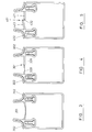
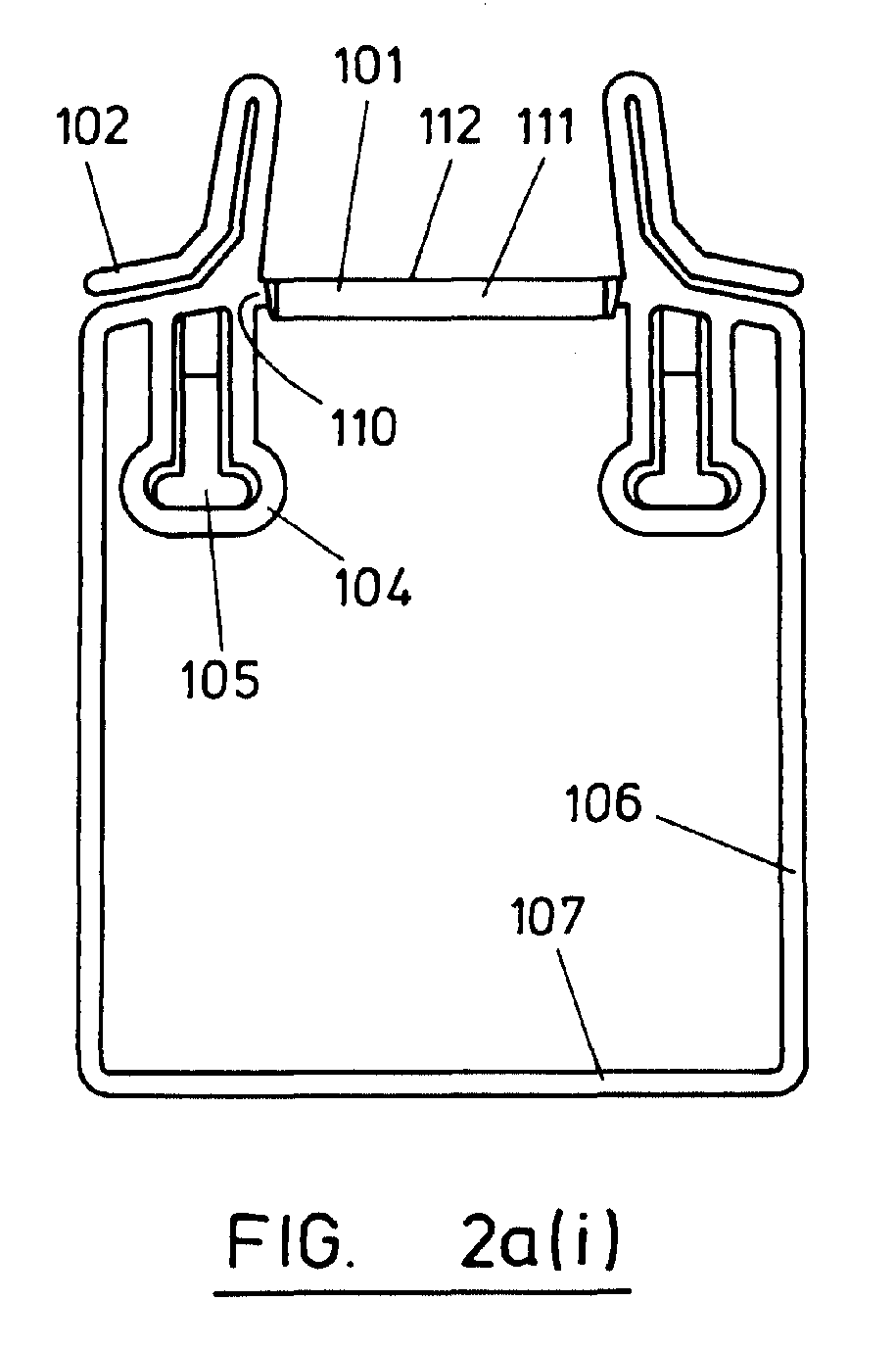
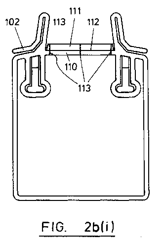
- the knitwear frame has a body member 101 comprising a frame member 110 and a locking flap 111 fastened thereto by means of a hinge 112.
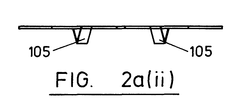
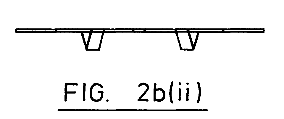
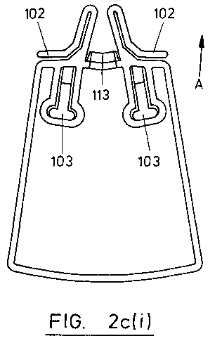
- the frame member 110 and locking flap 111 are provided with three transversely extending hinges 113 to enable the body member 101 to be collapsed when the locking flap 111 is in the open condition shown in Figure 2b but not when in the closed condition shown in Figure 2a.
- the middle hinge 113 acts in the opposite direction to outer hinges 113 to enable the frame member 110 and locking flap 111 to be collapsed along their length to cause legs 102 to move closer to each other.
- the body member 101 is generally rigid and the knitwear frame behaves in a similar manner to the prior art frame shown in Figures 1a to 1f.
- a pullover (not shown) can be mounted to the hanger by either stretching the neck portion of the pullover as in the case of the prior art, or by moving the locking flap 111 to the open condition shown in Figure 2b to enable the body member 101 to be collapsed as shown in Figure 2c.
- the transverse legs 102 can be moved towards each other and inserted into the neck portion of the pullover (not shown) without stretching of the pullover.
- the body member 101 can then be extended and made generally rigid by returning the locking flap 111 to its locking condition as shown in Figure 2a.
- the pullover is then folded around the frame and mounted thereto in a manner analogous to that described with reference to Figures 1a to 1f.
- the locking flap 111 is moved to its open condition as shown in Figure 2b to allow the body member 101 to collapse. This moves the legs 102 towards each other and enables the legs 102 to be pulled out of the neck portion of the pullover in the direction of arrow A in Figure 2c. At the same time, the lateral edges and/or the bottom portion of the pullover are disengaged from the clamping portions by the upward movement of the knitwear frame, so that the frame can be removed without the necessity of unfolding the pullover.
- the body member 301 comprises a first member 320 slidable within a second member 321 to vary the distance between legs 302.
- body member 401 comprises a pair of members 420, 421 which are attachable to each other by means of a pop fastener 422.
- the body member 401 is relatively rigid to prevent legs 402 from moving towards each other.
- the knitwear frame comprises a generally rigid body member 501 interconnecting clamping portions 503 from which respective folding members 506 extend.
- Engaging legs 502 are provided adjacent to the ends of the body member 501, and each engaging leg 502 is pivotable about a hinge 540 in the direction of arrow B in Figure 6 between a locked position as shown in the right hand portion of Figure 6, and a release position as shown in the left hand portion of Figure 6.
- the engaging leg 502 In the release position, the engaging leg 502 is accommodated within a recess 530 located between the corresponding clamping portion 503 and the end of the body member 501.
- the leg 502 In the locking position, the leg 502 extends laterally outwards above the associated clamping portion 503.
- the leg 502 is lockable in the locking position by means of a locking flap 531 which is pivotable about a hinge 532 to bring fasteners 533 on the locking flap 531 into engagement with corresponding holes 534 in the leg 502 and body member 501.
- each locking flap 531 is pivoted to its release position to enable the legs 502 to be pivoted about hinges 540 into the cooperating recess such that the legs 502 no longer extend laterally outwards to the same extent. As a result, the legs 502 no longer prevent withdrawal of the frame out of the neck portion of the pullover.
Landscapes
- Holders For Apparel And Elements Relating To Apparel (AREA)
- Details Of Garments (AREA)
Abstract
Description
laterally outwardly and a second position, and said means for enabling the engaging members to be moved towards each other comprises a fastener having a first condition in which said engaging member is locked in said first position and a second condition in which said engaging member is released from said first position.
Claims (12)
- A display frame for knitwear or the like, the display frame comprising:-a body member having a pair of engaging members, wherein each said engaging member comprises an engaging portion adapted to extend laterally outwards to engage the interior of a garment via a neck portion thereof to mount the body member to the exterior of the garment;a pair of fold members extending from respective lateral outer portions of the body member to enable respective lateral outer portions of the garment to be folded around each said fold member;clamping means arranged adjacent each end of the body member for receiving respective lateral outward portions of the garment when folded around the fold members and/or a bottom portion of the garment when folded upwards; andmeans for enabling said engaging members to be moved towards each other to enable the display frame to be removed from the garment.
- A display frame according to claim 1, wherein each said engaging member comprises an attachment portion extending substantially transversely to the body member and attaching the respective engaging portion thereto.
- A display frame according to claim 1 or 2, wherein each said engaging member is integrally formed with the body member.
- A display frame according to any one of the preceding claims, wherein said means for enabling the engaging members to be moved towards each other comprises a flap pivotally attached to the body member and a plurality of hinges provided in the body member and flap and extending substantially transversely thereto, wherein the flap is pivotable between locked and unlocked conditions such that the body member can be folded along said hinges only when the flap is in an unlocked condition.
- A display frame according to any one of claims 1 to 3, wherein said means for enabling the engaging members to be moved towards each other comprises a flexible portion of the body member arranged between the engaging members.
- A display frame according to any one of claims 1 to 3, wherein said means for enabling the engaging members to be moved towards each other comprises a first member slidable within a second member and forming part of the body member between the engaging members.
- A display frame according to any one of claims 1 to 3, wherein said means for enabling the engaging members to be moved towards each other comprises a first member fastenable to a second member to prevent the engaging members from being moved towards each other and forming part of the body member between the engaging members.
- A display frame according to any one of claims 1 to 3, wherein each said engaging portion is pivotable between a first position in which the engaging portion extends laterally outwardly and a second position, and said means for enabling the engaging members to be moved towards each other comprises a fastener having a first condition in which said engaging member is locked in said first position and a second condition in which said engaging member is released from said first position.
- A display frame according to claim 8, wherein each said fastener comprises a flap having engagements adapted to be received in corresponding holes in the corresponding engaging member.
- A display frame according to any one of the preceding claims, wherein each said fold member comprises a substantially straight edge extending from a lateral outer extremity of the body member.
- A display frame according to any one of the preceding claims, wherein the fold members are interconnected by means of a base member at the ends thereof remote from the body member.
- A display frame according to any one of the preceding claims, wherein each said clamping means comprises a generally coplanar first portion and a second portion adapted to resiliently clamp a portion of garment to said first portion.
Applications Claiming Priority (2)
| Application Number | Priority Date | Filing Date | Title |
|---|---|---|---|
| GBGB9709647.3A GB9709647D0 (en) | 1997-05-14 | 1997-05-14 | Garment display frame |
| GB9709647 | 1997-05-14 |
Publications (3)
| Publication Number | Publication Date |
|---|---|
| EP0878154A2 true EP0878154A2 (en) | 1998-11-18 |
| EP0878154A3 EP0878154A3 (en) | 2000-11-02 |
| EP0878154B1 EP0878154B1 (en) | 2006-07-19 |
Family
ID=10812203
Family Applications (1)
| Application Number | Title | Priority Date | Filing Date |
|---|---|---|---|
| EP19980303808 Expired - Lifetime EP0878154B1 (en) | 1997-05-14 | 1998-05-14 | Garment display frame |
Country Status (3)
| Country | Link |
|---|---|
| EP (1) | EP0878154B1 (en) |
| DE (1) | DE69835252D1 (en) |
| GB (1) | GB9709647D0 (en) |
Cited By (1)
| Publication number | Priority date | Publication date | Assignee | Title |
|---|---|---|---|---|
| NL1018247C2 (en) | 2001-06-08 | 2002-12-10 | Sara Lee De Nv | Device for preparing a beverage suitable for consumption such as coffee. |
Family Cites Families (5)
| Publication number | Priority date | Publication date | Assignee | Title |
|---|---|---|---|---|
| US1458113A (en) * | 1918-12-19 | 1923-06-05 | J L Sommer Mfg Co | Garment hanger |
| GB8718737D0 (en) * | 1987-08-07 | 1987-09-16 | Marks Spencer Plc | Knitwear display device |
| GB2257030B (en) * | 1991-06-28 | 1996-01-17 | Karner Birnbaum Ltd | Garment supports |
| JPH08252162A (en) * | 1995-03-16 | 1996-10-01 | Yoshitaka Higashiyama | Folding hanger |
| JPH1057206A (en) * | 1996-08-20 | 1998-03-03 | Nagai Package:Kk | Merchandise exhibition hanger |
-
1997
- 1997-05-14 GB GBGB9709647.3A patent/GB9709647D0/en active Pending
-
1998
- 1998-05-14 EP EP19980303808 patent/EP0878154B1/en not_active Expired - Lifetime
- 1998-05-14 DE DE69835252T patent/DE69835252D1/en not_active Expired - Lifetime
Cited By (2)
| Publication number | Priority date | Publication date | Assignee | Title |
|---|---|---|---|---|
| NL1018247C2 (en) | 2001-06-08 | 2002-12-10 | Sara Lee De Nv | Device for preparing a beverage suitable for consumption such as coffee. |
| WO2002100227A1 (en) | 2001-06-08 | 2002-12-19 | Sara Lee/De N.V. | Apparatus for preparing a beverage suitable for consumption, such as coffee |
Also Published As
| Publication number | Publication date |
|---|---|
| EP0878154B1 (en) | 2006-07-19 |
| GB9709647D0 (en) | 1997-07-02 |
| DE69835252D1 (en) | 2006-08-31 |
| EP0878154A3 (en) | 2000-11-02 |
Similar Documents
| Publication | Publication Date | Title |
|---|---|---|
| US5778575A (en) | Garment hanger hook size system | |
| US5090725A (en) | Collapsible garment cart | |
| US3542170A (en) | Article of luggage | |
| US6698966B2 (en) | Fastenings | |
| US7243884B2 (en) | Tilt-out laundry bag assembly | |
| US7748151B2 (en) | Stabilized A-frame sign stand | |
| CN213953195U (en) | Multi-Construction, Deployable Canopy Assembly Mounted to Vehicle | |
| US6076716A (en) | Hanger assembly | |
| USD441191S1 (en) | Winged laptop bag | |
| US5950845A (en) | Flush mounted valet | |
| WO2014028179A1 (en) | Foldable garment hanger with locking features | |
| US6293443B1 (en) | Foldable garment hanger for compactly storing garments when traveling | |
| US7185795B1 (en) | Collapsible hanger for suspending clothes and other items | |
| US20070045130A1 (en) | Display unit adapted to secure cuff links | |
| US6817504B2 (en) | Collapsible trunk organizer | |
| WO1999058031A1 (en) | Hanger assembly | |
| US5288120A (en) | Garment carrier | |
| US6206255B1 (en) | Clothes hanger adapter | |
| EP0878154B1 (en) | Garment display frame | |
| US3030058A (en) | Device for attaching a newspaper receptacle to a rural mailbox | |
| US5607129A (en) | Garment bag luggage cart | |
| US20070194064A1 (en) | Expandable and/or foldable hanger | |
| US20200170367A1 (en) | Garment hanger mechanism and system for travel bags and luggage | |
| US6499635B1 (en) | Garment hanger | |
| JPS6222223Y2 (en) |
Legal Events
| Date | Code | Title | Description |
|---|---|---|---|
| PUAI | Public reference made under article 153(3) epc to a published international application that has entered the european phase |
Free format text: ORIGINAL CODE: 0009012 |
|
| AK | Designated contracting states |
Kind code of ref document: A2 Designated state(s): BE DE ES FR GB IE IT NL PT |
|
| AX | Request for extension of the european patent |
Free format text: AL;LT;LV;MK;RO;SI |
|
| PUAL | Search report despatched |
Free format text: ORIGINAL CODE: 0009013 |
|
| AK | Designated contracting states |
Kind code of ref document: A3 Designated state(s): AT BE CH CY DE DK ES FI FR GB GR IE IT LI LU MC NL PT SE |
|
| AX | Request for extension of the european patent |
Free format text: AL;LT;LV;MK;RO;SI |
|
| RIC1 | Information provided on ipc code assigned before grant |
Free format text: 7A 47F 7/19 A, 7B 65D 85/18 B |
|
| 17P | Request for examination filed |
Effective date: 20010426 |
|
| AKX | Designation fees paid |
Free format text: BE DE ES FR GB IE IT NL PT |
|
| 17Q | First examination report despatched |
Effective date: 20030401 |
|
| GRAP | Despatch of communication of intention to grant a patent |
Free format text: ORIGINAL CODE: EPIDOSNIGR1 |
|
| GRAS | Grant fee paid |
Free format text: ORIGINAL CODE: EPIDOSNIGR3 |
|
| GRAA | (expected) grant |
Free format text: ORIGINAL CODE: 0009210 |
|
| AK | Designated contracting states |
Kind code of ref document: B1 Designated state(s): BE DE ES FR GB IE IT NL PT |
|
| PG25 | Lapsed in a contracting state [announced via postgrant information from national office to epo] |
Ref country code: NL Free format text: LAPSE BECAUSE OF FAILURE TO SUBMIT A TRANSLATION OF THE DESCRIPTION OR TO PAY THE FEE WITHIN THE PRESCRIBED TIME-LIMIT Effective date: 20060719 Ref country code: IT Free format text: LAPSE BECAUSE OF FAILURE TO SUBMIT A TRANSLATION OF THE DESCRIPTION OR TO PAY THE FEE WITHIN THE PRESCRIBED TIME-LIMIT;WARNING: LAPSES OF ITALIAN PATENTS WITH EFFECTIVE DATE BEFORE 2007 MAY HAVE OCCURRED AT ANY TIME BEFORE 2007. THE CORRECT EFFECTIVE DATE MAY BE DIFFERENT FROM THE ONE RECORDED. Effective date: 20060719 Ref country code: BE Free format text: LAPSE BECAUSE OF FAILURE TO SUBMIT A TRANSLATION OF THE DESCRIPTION OR TO PAY THE FEE WITHIN THE PRESCRIBED TIME-LIMIT Effective date: 20060719 |
|
| REG | Reference to a national code |
Ref country code: GB Ref legal event code: FG4D |
|
| REG | Reference to a national code |
Ref country code: IE Ref legal event code: FG4D |
|
| REF | Corresponds to: |
Ref document number: 69835252 Country of ref document: DE Date of ref document: 20060831 Kind code of ref document: P |
|
| PG25 | Lapsed in a contracting state [announced via postgrant information from national office to epo] |
Ref country code: DE Free format text: LAPSE BECAUSE OF FAILURE TO SUBMIT A TRANSLATION OF THE DESCRIPTION OR TO PAY THE FEE WITHIN THE PRESCRIBED TIME-LIMIT Effective date: 20061020 |
|
| PG25 | Lapsed in a contracting state [announced via postgrant information from national office to epo] |
Ref country code: ES Free format text: LAPSE BECAUSE OF FAILURE TO SUBMIT A TRANSLATION OF THE DESCRIPTION OR TO PAY THE FEE WITHIN THE PRESCRIBED TIME-LIMIT Effective date: 20061030 |
|
| PG25 | Lapsed in a contracting state [announced via postgrant information from national office to epo] |
Ref country code: PT Free format text: LAPSE BECAUSE OF FAILURE TO SUBMIT A TRANSLATION OF THE DESCRIPTION OR TO PAY THE FEE WITHIN THE PRESCRIBED TIME-LIMIT Effective date: 20061219 |
|
| NLV1 | Nl: lapsed or annulled due to failure to fulfill the requirements of art. 29p and 29m of the patents act | ||
| EN | Fr: translation not filed | ||
| PLBE | No opposition filed within time limit |
Free format text: ORIGINAL CODE: 0009261 |
|
| STAA | Information on the status of an ep patent application or granted ep patent |
Free format text: STATUS: NO OPPOSITION FILED WITHIN TIME LIMIT |
|
| 26N | No opposition filed |
Effective date: 20070420 |
|
| PG25 | Lapsed in a contracting state [announced via postgrant information from national office to epo] |
Ref country code: FR Free format text: LAPSE BECAUSE OF FAILURE TO SUBMIT A TRANSLATION OF THE DESCRIPTION OR TO PAY THE FEE WITHIN THE PRESCRIBED TIME-LIMIT Effective date: 20070511 |
|
| PG25 | Lapsed in a contracting state [announced via postgrant information from national office to epo] |
Ref country code: IE Free format text: LAPSE BECAUSE OF NON-PAYMENT OF DUE FEES Effective date: 20070514 |
|
| PG25 | Lapsed in a contracting state [announced via postgrant information from national office to epo] |
Ref country code: FR Free format text: LAPSE BECAUSE OF FAILURE TO SUBMIT A TRANSLATION OF THE DESCRIPTION OR TO PAY THE FEE WITHIN THE PRESCRIBED TIME-LIMIT Effective date: 20060719 |
|
| PGFP | Annual fee paid to national office [announced via postgrant information from national office to epo] |
Ref country code: GB Payment date: 20170519 Year of fee payment: 20 |
|
| REG | Reference to a national code |
Ref country code: GB Ref legal event code: PE20 Expiry date: 20180513 |
|
| PG25 | Lapsed in a contracting state [announced via postgrant information from national office to epo] |
Ref country code: GB Free format text: LAPSE BECAUSE OF EXPIRATION OF PROTECTION Effective date: 20180513 |