EP0877405A1 - Disjoncteur avec sectionneur - Google Patents
Disjoncteur avec sectionneur Download PDFInfo
- Publication number
- EP0877405A1 EP0877405A1 EP98401069A EP98401069A EP0877405A1 EP 0877405 A1 EP0877405 A1 EP 0877405A1 EP 98401069 A EP98401069 A EP 98401069A EP 98401069 A EP98401069 A EP 98401069A EP 0877405 A1 EP0877405 A1 EP 0877405A1
- Authority
- EP
- European Patent Office
- Prior art keywords
- contact
- shaft
- movable
- main
- arcing
- Prior art date
- Legal status (The legal status is an assumption and is not a legal conclusion. Google has not performed a legal analysis and makes no representation as to the accuracy of the status listed.)
- Withdrawn
Links
- 238000000926 separation method Methods 0.000 claims description 7
- 238000006073 displacement reaction Methods 0.000 abstract description 4
- 230000001052 transient effect Effects 0.000 description 6
- 101150075799 CPX1 gene Proteins 0.000 description 3
- 229910018503 SF6 Inorganic materials 0.000 description 3
- 239000002184 metal Substances 0.000 description 3
- SFZCNBIFKDRMGX-UHFFFAOYSA-N sulfur hexafluoride Chemical compound FS(F)(F)(F)(F)F SFZCNBIFKDRMGX-UHFFFAOYSA-N 0.000 description 3
- 229960000909 sulfur hexafluoride Drugs 0.000 description 3
- 239000004020 conductor Substances 0.000 description 2
- 230000001133 acceleration Effects 0.000 description 1
- 230000005540 biological transmission Effects 0.000 description 1
- 238000013016 damping Methods 0.000 description 1
- 238000010891 electric arc Methods 0.000 description 1
- 238000013021 overheating Methods 0.000 description 1
Images


Classifications
-
- H—ELECTRICITY
- H01—ELECTRIC ELEMENTS
- H01H—ELECTRIC SWITCHES; RELAYS; SELECTORS; EMERGENCY PROTECTIVE DEVICES
- H01H33/00—High-tension or heavy-current switches with arc-extinguishing or arc-preventing means
- H01H33/60—Switches wherein the means for extinguishing or preventing the arc do not include separate means for obtaining or increasing flow of arc-extinguishing fluid
- H01H33/66—Vacuum switches
- H01H33/666—Operating arrangements
- H01H33/6661—Combination with other type of switch, e.g. for load break switches
Definitions
- the invention relates to a generator circuit breaker comprising a fixed tubular main contact and a tubular main contact movable relative to the main tubular contact fixed according to a certain longitudinal direction, the main contacts defining a volume inside which is placed a vacuum or gas bulb having a fixed arcing contact and an arcing contact movable relative to the fixed arcing contact in said longitudinal direction, a means of synchronization ensuring the separation of the main front contacts separation of arcing contacts.
- Such a circuit breaker is usually placed between a generator a power plant and a transformer connected to an energy transmission line.
- the main contacts are massive enough to support high nominal currents without overheating. They define a relatively large volume important. which is more difficult to put under gas pressure or under empty, than a smaller bulb, placed inside of this volume.
- the bulb includes a fixed arcing contact and a contact movable arc, less massive because supporting only the current breaker break.
- the object of the invention is to provide a generator circuit breaker in which the main and movable arcing contacts are actuated by mechanical means in limited number and having a simple synchronization.
- the invention relates to a generator circuit breaker comprising a fixed tubular main contact and a main contact tubular movable with respect to the following main tubular contact a certain longitudinal direction, the main contacts defining a volume inside which is placed a vacuum or gas having a fixed arcing contact and an arcing contact movable relative in fixed arc contact, in said longitudinal direction, a means synchronization ensuring the separation of the main contacts before the separation of the arcing contacts, characterized in that the means synchronization comprises a shaft extending transversely to the longitudinal direction and which carries a first lever connected to the contact main mobile, and a hub mounted inside the shaft and which carries a second lever connected to the movable arcing contact, the shaft and the hub being conformed on a certain part in two sectors between which is arranged a spring, the levers forming between them a certain angle in a transverse plane of the tree, the tree performing initially a rotation which moves the main contact mobile and rotates through the spring the hub which moves the
- Synchronization of the movement of the mobile main contact with respect to the moving arcing contact is obtained simply by using two levers forming between them a certain angle in a plane transverse to the tree, and having lengths in a certain relationship.
- the main mobile contact When the circuit breaker opens, the main mobile contact, relatively massive, moves at a substantially constant speed. which minimizes the power of the mechanical control.
- the movable arcing contact first moves more slowly than the main contact, allowing him to travel a distance sufficient to withstand a transient electrical voltage before the arcing contact does not open. Then the movable arcing contact moves more faster than the moving main contact, reducing the exposure time of the arcing contacts to the breaking current.
- the generator circuit breaker further includes a disconnector having a movable contact rod in said longitudinal direction compared to a crown of contact fingers integral with the vacuum or gas bulb.
- the disconnector which has no breaking capacity, must not open only when the arcing contact is open.
- the generator circuit breaker according to the invention makes it possible to move and synchronize the movable contact of the disconnector using a number limited additional resources compared to the resources already put used for moving and synchronizing contacts main and movable arc.
- the circuit breaker generator includes a disconnector with a movable contact rod in said longitudinal direction relative to a crown of contact fingers secured to the vacuum or gas bulb, the contact being connected to the shaft by means of a connecting rod.
- the synchronization of the displacement of the contact rod by relationship to mobile contacts is simply achieved by the cooperation of the tree and the connecting rod assembly, which makes it possible to open the disconnector when, on the one hand, the mobile main contact has made a stroke sufficient to hold a transient electrical voltage, and when on the other hand, the movable arcing contact has made a stroke sufficient dielectric strength.
- Figure 1 shows schematically a sectional view longitudinal of the circuit breaker comprising a disconnector.
- Figure 2 shows schematically the shaft and the hub of the circuit breaker in longitudinal and side views.
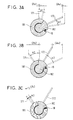
- FIGS. 3A to 3C illustrate an example of synchronization of the main and arcing movable contacts when the circuit breaker opens.
- the circuit breaker according to the invention is inserted between the portions 1 and 2 of a phase conductor of an electric line.
- Portions 1 and 2 of the conductor are mechanically connected and electrically to fixed main contacts 4 and 5 of the circuit breaker. These contacts cooperate with a main contact 6 movable relative to to the main fixed contacts in a longitudinal direction D.
- the cooperation between the fixed main contact 5 and the main contact mobile 6 is provided by a ring of contact fingers 5A.
- a sliding contact 4A ensures cooperation between the fixed main contact 4 and the mobile main contact 6.
- the fixed main contacts 4 and 5, and the mobile main contact 6 have a tubular shape defining a volume inside which is placed a vacuum or gas bulb 15 such as sulfur hexafluoride SF 6 .
- This bulb comprises a cylindrical insulating envelope 15A provided with a metal bottom 15B provided with a hole 15C through which a movable arcing contact 15D slides.
- the bulb is kept fixed in the volume by arms (not shown) fixed on the bottom 15B.
- the bulb is sealed at the hole by a 15E bellows
- the vacuum or the gas being consigned in the bulb it reigns in the volume defined by the main contacts an equal pressure of preferably air pressure.
- the bulb is closed on the side opposite the bottom 15B by a bottom metal 15F carrying a fixed arcing contact 15G mounted inside the bulb, and a crown of metal contact fingers 15H mounted on the outside of the bulb.
- 15G fixed arcing contact present at one end a hollow cylinder 15J inside which slides the movable arcing contact 15D.
- a shaft 181 extending transversely to the longitudinal direction D and mounted with an inner hub 182.
- the shaft and the hub are conformed on part B into two coaxial sectors 181B and 182B, sector 181B, integral with the tree, having for example an arc of 270 degrees, and sector 182B, integral with the hub, an arc for example of 70 degrees.
- the two sectors have two faces 181F and 182F in gaze, forming between them an arc of 20 degrees, and connected by a spring 19.
- the shaft 181 carries a first lever 171 secured to the contact main mobile 6 via a rigid rod 221
- the hub 182 carries a second lever 172 secured to the movable arcing contact 15D via a rigid rod 222.
- the two levers form in a plane transverse to the shaft 181, an angle for example equal to 65 degrees.
- the length of the lever 172 is greater than that of the lever 171, for example in a ratio equal to 1.75.
- a single control means moves in rotation of the shaft 181, for example, at constant speed.
- the total angle of rotation of the shaft 181, for example equal to 60 degrees, is the sum of three angles each corresponding to a phase of the opening of the circuit breaker.
- the circuit breaker In the initial state, the circuit breaker is closed. A first phase opening is implemented by a rotation of the shaft 181 of a first angle ⁇ 1, which causes a translation of the main contact mobile 6 by means of the lever 171 and the rigid rod 221.
- the stiffness constant of the spring 19 is such that the rotation of the shaft 181 causes the rotation of the hub 182 by an angle substantially equal.
- the hub In its rotation, the hub moves in translation the movable arcing contact 15D by means of the lever 172 and the rigid rod 222.
- the angle ⁇ 1 for example equal to 15 degrees, is chosen, on the one hand, to allow the movable main contact 6 to make a stroke relatively large, to separate it from the fixed main contact 5 a sufficient distance to hold a transient electrical voltage, and on the other hand, to allow the movable arcing contact 15D, to perform a relatively small stroke, keeping it in contact with the fixed arcing contact 15G via the cylinder 15J.
- FIGS. 3A to 3C are represented the stroke of the contact main movable 6 (CPx) and the stroke of the movable arcing contact 15D (CAx) as a function of the angle of rotation of the shaft 181, for the values example cited above (angle between lever 171 and lever 172 equal to 65 degrees, ratio of the lengths of the levers equal to 1.75).
- FIG. 3A illustrates the rotation of angle ⁇ 1, at the end of which the stroke CPx1 of the movable main contact 6 is greater than the stroke CAx1 of the movable arcing contact 15D.
- the difference in the travel of the mobile contacts main 6 and arc 15D is controlled by the angle A formed by the levers 171 and 172 in a plane transverse to the shaft 181. as well as by the ratio of their length.
- FIG. 3B a second phase of opening the circuit breaker is implemented by rotating the shaft 181 by a second angle ⁇ 2.
- the spring 19 drives as previously the hub 182 in rotation of a substantially equal angle.
- the angle ⁇ 2 is chosen to allow the movable arcing contact 15D to make a full stroke CAx1 + CAx2 at the end of which the distance which separates it from the fixed arcing contact 15G is sufficient to withstand a dielectric voltage in the vacuum interrupter or in sulfur hexafluoride SF 6 .
- This complete stroke corresponds to the distance which separates the cylinder 15J from the bottom 15B of the bulb.
- the mobile main contact 6 extends his separation run, after which he has completed a full stroke CPx1 + CPx1, which is equivalent to the stroke complete CAx1 + CAx2 of the movable arcing contact 6.
- This equivalence between the two races reflects the fact that the speed of movement in translation of the movable arcing contact 15D has become greater than the speed of the movable main contact 6 during the angle rotation ⁇ 2.
- the relatively high speed of the movable arcing contact 15D makes it possible to open the circuit breaker quickly without excessively exposing the arcing contacts to the breaking current and also makes it possible to blow SF 6 gas with greater efficiency on an electric arc formed between arcing contacts.
- the relatively low speed of the movable main contact 6, which has greater inertia by its more massive dimensions, is also advantageous, making it possible to minimize the power of the control of the shaft 181.
- the movable main contact 6 performs, in a third phase, an overtravel compared to the arcing contact mobile 15D.
- This overtravel is implemented, FIG. 3C. by one rotation of the shaft 181 by a third angle ⁇ 3, equal for example to 11 degrees.
- the hub 182 being locked in rotation by a stop 13 fixed rise in the volume of the circuit breaker or on the arcing contact mobile 15D, spring 19 compresses to allow rotation ⁇ 3 of the shaft 181 and a damping of the rotation at the end of opening.
- the end of travel of the movable main contact 6 corresponds to a sufficient distance of dielectric withstand in air.
- the vacuum interrupter 15 is electrically connected in series with a disconnector comprising a movable contact 30 cooperating, at a first end, with finger crown 15H.
- the contact mobile 30 is a rod passing through a disc 5C machined with the tube 5. This disc carries a crown 5D of contact fingers electrical to ensure the electrical connection between the rod 30 and the tube 5.
- the other end of the contact rod 30 is articulated with a first connecting rod 21 mounted in rotation about an axis 23 perpendicular to the median plane of the circuit breaker, represented by the plane of Figure 1.
- a second connecting rod 191 connects one end of the connecting rod 21 to tree 181.
- the connecting rods 21 and 191 allow, using the single control of the shaft 181, to move and synchronize the contact rod 30 of the disconnector with respect to moving contacts 6 and 15D of the circuit breaker
- the disconnector In the initial state, the disconnector is closed, in position P0 on the figure 1. In the first phase of opening, a rotation of angle ⁇ 1 of the shaft 181, causes a displacement in translation of the rod contact 30 to position P1, in which it remains in contact with the contact fingers 15H. Thus, the disconnector remains closed while the main contact 6 reaches the sufficient holding distance at a transient electric voltage.
- a rotation of angle ⁇ 2 of the shaft 181 translates the contact rod 30 towards the position P2, which is, in the example, the same position as the position P0.
- the disconnector is closed, while the movable arcing contact 15D reaches the sufficient dielectric withstand distance corresponding to its full stroke.
- a rotation of the tree 181 from the angle ⁇ 3, translates the contact rod 30 towards the position P3, which opens the disconnector.
- the full stroke of the rod contact 30 corresponds to a sufficient distance of dielectric withstand in the air.
- the synchronization of the displacement of the contact rod 30 by relationship to mobile contacts is simply achieved by the cooperation of the shaft and connecting rods, which opens the disconnector when on the one hand, the main mobile contact has made a run sufficient to withstand a transient electrical voltage, and when on the other hand, the movable arcing contact has made a sufficient stroke for dielectric strength in vacuum or gas in the bulb.
Landscapes
- High-Tension Arc-Extinguishing Switches Without Spraying Means (AREA)
- Arc-Extinguishing Devices That Are Switches (AREA)
- Breakers (AREA)
- Driving Mechanisms And Operating Circuits Of Arc-Extinguishing High-Tension Switches (AREA)
Abstract
Le disjoncteur comprenant des contacts principaux (4,5,6) et des contacts d'arc (15D,15G) est caractérisé par un arbre (181) portant un premier levier (171) relié au contact principal mobile (6), et par un moyeu (182) monté à l'intérieur de l'arbre (181) et portant un deuxième levier (172) relié au contact d'arc mobile (15D), l'arbre (181) et le moyeu (182) étant conformés sur une certaine partie en deux secteurs (181B, 182B) entre lesquels est disposé un ressort (19). Une commande unique entraîne en rotation l'arbre (181), qui, dans un premier temps, entraîne le moyeu (182) par l'intermédiaire du ressort (19), la rotation de l'arbre (181) et du moyeu (182) permettant de déplacer respectivement le contact principal mobile (6) et le contact d'arc mobile (15D), et qui, dans un deuxième temps, effectue une rotation supplémentaire, le moyeu (182) restant immobilisé en rotation par l'action d'une butée (13). Cet agencement permet une synchronisation simple et unique permettant d'ouvrir les contacts principaux avant les contacts d'arc. <IMAGE>
Description
L'invention concerne un disjoncteur de générateur comprenant
un contact principal tubulaire fixe et un contact principal tubulaire
mobile par rapport au contact principal tubulaire fixe suivant une
certaine direction longitudinale, les contacts principaux définissant un
volume à l'intérieur duquel est disposée une ampoule à vide ou à gaz
ayant un contact d'arc fixe et un contact d'arc mobile par rapport au
contact d'arc fixe suivant ladite direction longitudinale, un moyen de
synchronisation assurant la séparation des contacts principaux avant
la séparation des contacts d'arc.
Un tel disjoncteur est habituellement placé entre un générateur
d'une centrale de production électrique et un transformateur relié à
une ligne de transport d'énergie.
D'une manière connue, les contacts principaux sont
suffisamment massifs pour supporter des courants nominaux élevés
sans s'échauffer exagérément. Ils définissent un volume relativement
important. qui est plus difficile à mettre sous pression de gaz ou sous
vide, qu'une ampoule de dimension plus réduite, disposée à l'intérieur
de ce volume. L'ampoule comprend un contact d'arc fixe et un contact
d'arc mobile, moins massifs parce que ne supportant que le courant
de coupure du disjoncteur.
Dans la demande de brevet FR 89 13279, le contact principal et
le contact d'arc mobiles s'étendant dans une même direction
longitudinale, sont déplacés en translation parallèlement à cette
direction, par des moyens pneumatiques à pistons et cylindres.
Ces moyens se révèlent non dépourvus d'inconvénients.
D'une part. il est nécessaire de prévoir des électrovannes pour
synchroniser le déplacement des vérins pneumatiques du contact
principal et du contact d'arc mobiles. En particulier, le contact principal
mobile doit accomplir un déplacement suffisant pour tenir une tension
électrique transitoire avant que le contact d'arc mobile ne s'ouvre.
D'autre part, l'obtention en fin de course du contact d'arc mobile.
d'une accélération satisfaisante permettant d'ouvrir avec une plus
grande efficacité le disjoncteur, n'est possible qu'avec un dispositif
assez sophistiqué d'alimentation en gaz des vérins pneumatiques.
Le but de l'invention est de fournir un disjoncteur de générateur
dans lequel les contacts principal et d'arc mobiles sont actionnés par
des moyens mécaniques en nombre limité et présentant une
synchronisation simple.
A cet effet, l'invention a pour objet un disjoncteur de générateur
comprenant un contact principal tubulaire fixe et un contact principal
tubulaire mobile par rapport au contact principal tubulaire fixe suivant
une certaine direction longitudinale, les contacts principaux définissant
un volume à l'intérieur duquel est disposée une ampoule à vide ou à
gaz ayant un contact d'arc fixe et un contact d'arc mobile par rapport
au contact d'arc fixe, suivant ladite direction longitudinale, un moyen
de synchronisation assurant la séparation des contacts principaux
avant la séparation des contacts d'arc, caractérisé en ce que le moyen
de synchronisation comprend un arbre s'étendant transversalement à
la direction longitudinale et qui porte un premier levier relié au contact
principal mobile, et un moyeu monté à l'intérieur de l'arbre et qui porte
un deuxième levier relié au contact d'arc mobile, l'arbre et le moyeu
étant conformés sur une certaine partie en deux secteurs entre
lesquels est disposé un ressort, les leviers formant entre eux un
certain angle dans un plan transversal de l'arbre, l'arbre effectuant
dans un premier temps une rotation qui déplace le contact principal
mobile et entraíne en rotation par l'intermédiaire du ressort le moyeu
qui déplace le contact d'arc mobile, et effectuant dans un deuxième
temps, une rotation supplémentaire, le moyeu restant immobilisé en
rotation par l'action d'une butée.
La liaison en rotation de l'arbre et du moyeu par l'intermédiaire
d'un ressort permet de déplacer en translation les contacts mobiles à
partir d'une commande mécanique unique.
La synchronisation du déplacement du contact principal mobile
par rapport au contact d'arc mobile est obtenue simplement à l'aide de
deux leviers formant entre eux un certain angle dans un plan
transversal à l'arbre, et ayant des longueurs dans un certain rapport.
A l'ouverture du disjoncteur, le contact principal mobile,
relativement massif, se déplace à une vitesse sensiblement constante.
ce qui permet de minimiser la puissance de la commande mécanique.
Le contact d'arc mobile se déplace tout d'abord plus lentement que le
contact principal, permettant à celui-ci de parcourir une distance
suffisante pour tenir une tension électrique transitoire avant que le
contact d'arc ne s'ouvre. Puis le contact d'arc mobile se déplace plus
rapidement que le contact principal mobile, permettant de réduire le
temps d'exposition des contacts d'arc au courant de coupure.
Le disjoncteur de générateur comprend en outre un sectionneur
ayant une tige de contact mobile suivant ladite direction longitudinale
par rapport à une couronne de doigts de contact solidaires de
l'ampoule à vide ou à gaz.
Le sectionneur, qui n'a aucun pouvoir de coupure, ne doit
s'ouvrir que lorsque que le contact d'arc est ouvert. Avantageusement,
le disjoncteur de générateur selon l'invention permet de déplacer et de
synchroniser le contact mobile du sectionneur à l'aide d'un nombre
limité de moyens supplémentaires par rapport aux moyens déjà mis
en oeuvre pour le déplacement et la synchronisation des contacts
principal et d'arc mobiles.
Selon un mode de réalisation de l'invention, le disjoncteur de
générateur comprend un sectionneur avec une tige de contact mobile
suivant ladite direction longitudinale par rapport à une couronne de
doigts de contact solidaires de l'ampoule à vide ou à gaz, la tige de
contact étant reliée à l'arbre par l'intermédiaire d'un embiellage.
La synchronisation du déplacement de la tige de contact par
rapport aux contacts mobiles est simplement réalisée par la
coopération de l'arbre et de l'embiellage, qui permet d'ouvrir le
sectionneur lorsque d'une part, le contact principal mobile a effectué
une course suffisante pour tenir une tension électrique transitoire, et
lorsque d'autre part, le contact d'arc mobile a effectué une course
suffisante de tenue diélectrique.
D'autres caractéristiques et avantages de l'invention apparaítront
à la lecture de la description de deux modes de réalisation illustrés par
les figures 1 à 3.
La figure 1 montre schématiquement une vue en coupe
longitudinale du disjoncteur comprenant un sectionneur.
La figure 2 montre schématiquement l'arbre et le moyeu du
disjoncteur en vues longitudinale et de côté.
Les figures 3A à 3C illustrent un exemple de synchronisation des
contacts mobiles principal et d'arc à l'ouverture du disjoncteur.
Dans la figure 1, le disjoncteur selon l'invention est inséré entre
les portions 1 et 2 d'un conducteur de phase d'une ligne électrique.
Les portions 1 et 2 du conducteur sont reliées mécaniquement et
électriquement à des contacts principaux fixes 4 et 5 du disjoncteur.
Ces contacts coopèrent avec un contact principal 6 mobile par rapport
aux contacts principaux fixes suivant une direction longitudinale D. La
coopération entre le contact principal fixe 5 et le contact principal
mobile 6 est assurée par une couronne de doigts de contact 5A. Un
contact glissant 4A assure la coopération entre le contact principal fixe
4 et le contact principal mobile 6.
Les contacts principaux fixes 4 et 5, et le contact principal mobile
6 ont une forme tubulaire définissant un volume à l'intérieur duquel est
disposée une ampoule 15 à vide ou à gaz comme l'hexafluorure de
soufre SF6. Cette ampoule comprend une enveloppe isolante
cylindrique 15A munie d'un fond métallique 15B pourvu d'un trou 15C
par lequel coulisse un contact d'arc mobile 15D. L'ampoule est
maintenue fixe dans le volume par des bras non représentés fixés sur
le fond 15B. L'étanchéité de l'ampoule est assurée au niveau du trou
par un soufflet 15E
Le vide ou le gaz étant consigné dans l'ampoule, il règne dans le
volume défini par les contacts principaux une pression égale de
préférence à la pression de l'air.
L'ampoule est fermée du côté opposé au fond 15B par un fond
métallique 15F portant un contact d'arc fixe 15G monté à l'intérieur de
l'ampoule, et une couronne de doigts métalliques de contact 15H
montés à l'extérieur de l'ampoule. Le contact d'arc fixe 15G présente
à une extrémité un cylindre creux 15J à l'intérieur duquel coulisse le
contact d'arc mobile 15D.
Dans le volume du contact principal fixe 4 est disposé, figure 2,
un arbre 181 s'étendant transversalement à la direction longitudinale
D et monté avec un moyeu intérieur 182. L'arbre et le moyeu sont
conformés sur une partie B en deux secteurs 181B et 182B coaxiaux,
le secteur 181B, solidaire de l'arbre, ayant par exemple un arc de 270
degrés, et le secteur 182B, solidaire du moyeu, un arc par exemple de
70 degrés. Les deux secteurs présentent deux faces 181F et 182F en
regard, formant entre elles un arc de 20 degrés, et reliées par un
ressort 19.
L'arbre 181 porte un premier levier 171 solidaire du contact
principal mobile 6 par l'intermédiaire d'un tige rigide 221 Le moyeu
182 porte un deuxième levier 172 solidaire du contact d'arc mobile
15D par l'intermédiaire d'une tige rigide 222. Les deux leviers forment
dans un plan transversal à l'arbre 181, un angle par exemple égal à 65
degrés. La longueur du levier 172 est supérieure à celle du levier 171,
par exemple dans un rapport égal à 1,75.
Le fonctionnement du disjoncteur est décrit ci-dessous.
Un moyen de commande unique, non représenté, déplace en
rotation l'arbre 181, par exemple, à vitesse constante. L'angle total de
rotation de l'arbre 181, par exemple égal à 60 degrés, est la somme
de trois angles correspondant chacun à une phase de l'ouverture du
disjoncteur.
Dans l'état initial, le disjoncteur est fermé. Une première phase
d'ouverture est mise en oeuvre par une rotation de l'arbre 181 d'un
premier angle α1, qui entraíne une translation du contact principal
mobile 6 par l'intermédiaire du levier 171 et de la tige rigide 221. Dans
le même temps, la constante de raideur du ressort 19 est telle que la
rotation de l'arbre 181 entraíne la rotation du moyeu 182 d'un angle
sensiblement égal. Dans sa rotation, le moyeu déplace en translation
le contact d'arc mobile 15D par l'intermédiaire du levier 172 et de la
tige rigide 222.
L'angle α1, par exemple égal à 15 degrés, est choisi, d'une part,
pour permettre au contact principal mobile 6 d'effectuer une course
relativement importante, pour le séparer du contact principal fixe 5
d'une distance suffisante pour tenir une tension électrique transitoire,
et d'autre part, pour permettre au contact d'arc mobile 15D, d'effectuer
une course relativement faible, le maintenant en contact avec le
contact d'arc fixe 15G par l'intermédiaire du cylindre 15J.
Sur les figures 3A à 3C sont représentées la course du contact
principal mobile 6 (CPx) et la course du contact d'arc mobile 15D
(CAx) en fonction de l'angle de rotation de l'arbre 181, pour les valeurs
d'exemple citées précédemment (angle entre le levier 171 et le levier
172 égal à 65 degrés, rapport des longueurs des leviers égal à 1,75).
La figure 3A illustre la rotation d'angle α1, à l'issue de laquelle la
course CPx1 du contact principal mobile 6 est supérieure à la course
CAx1 du contact d'arc mobile 15D.
De même, la différence des courses des contacts mobiles
principal 6 et d'arc 15D est contrôlée par l'angle A formé par les
leviers 171 et 172 dans un plan transversal à l'arbre 181. ainsi que par
le rapport de leur longueur.
Figure 3B, une deuxième phase d'ouverture du disjoncteur est
mise en oeuvre par une rotation de l'arbre 181 d'un deuxième angle
α2. Le ressort 19 entraíne comme précédemment le moyeu 182 en
rotation d'un angle sensiblement égal.
L'angle α2, par exemple égal à 34 degrés, est choisi pour
permettre au contact d'arc mobile 15D d'effectuer une course
complète CAx1 + CAx2 à la fin de laquelle la distance qui le sépare du
contact d'arc fixe 15G est suffisante pour tenir une tension diélectrique
dans l'ampoule à vide ou à l'hexafluorure de Soufre SF6. Cette course
complète correspond à la distance qui sépare le cylindre 15J du fond
15B de l'ampoule.
Dans cette deuxième phase, le contact principal mobile 6
prolonge sa course de séparation, à l'issue de laquelle, il a effectué
une course complète CPx1 + CPx1, qui est équivalente à la course
complète CAx1 + CAx2 du contact d'arc mobile 6. Cette équivalence
entre les deux courses traduit le fait que la vitesse de déplacement en
translation du contact d'arc mobile 15D est devenue supérieure à la
vitesse du contact principal mobile 6 au cours de la rotation d'angle
α2.
La vitesse relativement élevée du contact d'arc mobile 15D
permet d'ouvrir le disjoncteur rapidement sans exposer exagérément
les contacts d'arc au courant de coupure et permet aussi de souffler
avec une plus grande efficacité le gaz SF6 sur un arc électrique formé
entre les contacts d'arc. La vitesse relativement faible du contact
principal mobile 6, qui possède, par ses dimensions plus massives
une inertie plus grande, est également avantageuse, permettant de
minimiser la puissance de la commande de l'arbre 181.
La distance de tenue diélectrique de l'air étant supérieure à la
distance de tenue diélectrique dans le vide ou dans le gaz
d'hexafluorure de Soufre, le contact principal mobile 6 effectue, dans
une troisième phase, une surcourse par rapport au contact d'arc
mobile 15D. Cette surcourse est mise en oeuvre, figure 3C. par une
rotation de l'arbre 181 d'un troisième angle α3, égal par exemple à 11
degrés. Le moyeu 182 étant bloqué en rotation par une butée 13
montée fixe dans le volume du disjoncteur ou sur le contact d'arc
mobile 15D, le ressort 19 se comprime pour permettre la rotation α3
de l'arbre 181 et un amortissement de la rotation en fin d'ouverture.
Ainsi, la fin de course du contact principal mobile 6 correspond à une
distance suffisante de tenue diélectrique dans l'air.
L'ampoule à vide 15 est reliée électriquement en série avec un
sectionneur comprenant un contact mobile 30 coopérant, à une
première extrémité, avec la couronne de doigts 15H. Le contact
mobile 30 est une tige traversant un disque 5C venu d'usinage avec le
tube 5. Ce disque porte une couronne 5D de doigts de contact
électrique pour assurer la liaison électrique entre la tige 30 et le
tube 5.
L'autre extrémité de la tige de contact 30 est articulée avec une
première bielle 21 montée en rotation autour d'un axe 23
perpendiculaire au plan médian du disjoncteur, représenté par le plan
de la figure 1. Une deuxième bielle 191 relie une extrémité de la bielle
21 à l'arbre 181.
Les bielles 21 et 191 permettent, à l'aide de la commande unique
de l'arbre 181, de déplacer et de synchroniser la tige de contact 30 du
sectionneur par rapport aux contacts mobiles 6 et 15D du disjoncteur
Le fonctionnement du sectionneur est décrit ci-dessous.
Dans l'état initial, le sectionneur est fermé, en position P0 sur la
figure 1. Dans la première phase d'ouverture, une rotation d'angle α1
de l'arbre 181, entraíne un déplacement en translation de la tige de
contact 30 vers la position P1, dans laquelle elle reste en contact avec
les doigts de contact 15H. Ainsi, le sectionneur reste fermé alors que
le contact principal 6 atteint la distance suffisante de tenue à une
tension électrique transitoire.
Dans la deuxième phase d'ouverture, une rotation d'angle α2 de
l'arbre 181, entraíne en translation la tige de contact 30 vers la
position P2, qui est, dans l'exemple, la même position que la position
P0. Le sectionneur est fermé, alors que le contact d'arc mobile 15D
atteint la distance suffisante de tenue diélectrique correspondant à sa
course complète.
Dans la troisième phase d'ouverture, une rotation de l'arbre 181
de l'angle α3, entraíne en translation la tige de contact 30 vers la
position P3, qui ouvre le sectionneur. La course complète de la tige de
contact 30 correspond à une distance suffisante de tenue diélectrique
dans l'air.
La synchronisation du déplacement de la tige de contact 30 par
rapport aux contacts mobiles est simplement réalisée par la
coopération de l'arbre et des bielles, qui permet d'ouvrir le sectionneur
lorsque d'une part, le contact principal mobile a effectué une course
suffisante pour tenir une tension électrique transitoire, et lorsque
d'autre part, le contact d'arc mobile a effectué une course suffisante
pour la tenue diélectrique dans le vide ou le gaz de l'ampoule.
Claims (2)
- Disjoncteur de générateur comprenant un contact principal tubulaire fixe (5) et un contact principal tubulaire mobile (6) par rapport au contact principal tubulaire fixe suivant une certaine direction longitudinale (D), les contacts principaux définissant un volume à l'intérieur duquel est disposée une ampoule à vide ou à gaz (15) avec un contact d'arc fixe (15G) et un contact d'arc mobile (15D) par rapport au contact d'arc fixe suivant ladite direction longitudinale (D), un arbre (181) s'étendant transversalement à la direction longitudinale (D) et qui porte un premier levier (171) relié au contact principal mobile (6), et un moyen de synchronisation assurant la séparation des contacts principaux avant la séparation des contacts d'arc, caractérisé en ce que le moyen de synchronisation comprend un moyeu (182) qui est monté à l'intérieur de l'arbre (181) et qui porte un deuxième levier (172) relié au contact d'arc mobile (15D), l'arbre (181) et le moyeu (182) étant conformés sur une certaine partie en deux secteurs (181B, 182B) entre lesquels est disposé un ressort (19), les leviers (171, 172) formant entre eux un certain angle (A) dans un plan transversal de l'arbre (181), l'arbre (181) effectuant dans un premier temps une rotation qui déplace le contact principal mobile (6) et entraíne en rotation par l'intermédiaire du ressort (19) le moyeu (182) qui déplace le contact d'arc mobile (15D), et effectuant dans un deuxième temps, une rotation supplémentaire, le moyeu (182) restant immobilisé en rotation par l'action d'une butée (13).
- Un disjoncteur selon la revendication 1, comprenant en outre un sectionneur ayant une tige de contact (30) mobile suivant ladite direction longitudinale (D) par rapport à une couronne de doigts de contact (15H) solidaires de l'ampoule (15), dans lequel la tige de contact (30) est reliée à l'arbre (181) par l'intermédiaire d'un embiellage (191,21).
Applications Claiming Priority (2)
| Application Number | Priority Date | Filing Date | Title |
|---|---|---|---|
| FR9705639 | 1997-05-07 | ||
| FR9705639A FR2763171B1 (fr) | 1997-05-07 | 1997-05-07 | Disjoncteur avec sectionneur |
Publications (1)
| Publication Number | Publication Date |
|---|---|
| EP0877405A1 true EP0877405A1 (fr) | 1998-11-11 |
Family
ID=9506676
Family Applications (1)
| Application Number | Title | Priority Date | Filing Date |
|---|---|---|---|
| EP98401069A Withdrawn EP0877405A1 (fr) | 1997-05-07 | 1998-04-30 | Disjoncteur avec sectionneur |
Country Status (7)
| Country | Link |
|---|---|
| US (1) | US5898151A (fr) |
| EP (1) | EP0877405A1 (fr) |
| KR (1) | KR19980086793A (fr) |
| BR (1) | BR9801183A (fr) |
| CA (1) | CA2235082A1 (fr) |
| FR (1) | FR2763171B1 (fr) |
| ID (1) | ID20557A (fr) |
Cited By (9)
| Publication number | Priority date | Publication date | Assignee | Title |
|---|---|---|---|---|
| FR2896336A1 (fr) * | 2006-01-17 | 2007-07-20 | Areva T & D Sa | Disjoncteur sectionneur d'alternateur de structure compacte |
| WO2009093919A3 (fr) * | 2008-01-25 | 2009-09-17 | Edward Januszkiewicz | Sectionneur de tension moyenne s'utilisant spécialement dans un équipement électrique minier |
| US7705262B2 (en) | 2006-05-12 | 2010-04-27 | Areva T&D Sa | Alternator disconnector circuit-breaker by a servomotor |
| US7718913B2 (en) | 2006-06-23 | 2010-05-18 | Areva T&D Sa | Actuation by cylindrical CAM of a circuit-breaker for an alternator |
| US9269514B2 (en) | 2011-12-21 | 2016-02-23 | Alstom Technology Ltd. | Device for protection against particles generated by an electric switching arc |
| FR3029351A1 (fr) * | 2014-12-02 | 2016-06-03 | Alstom Technology Ltd | Dispositif de coupure electrique integrant un disjoncteur et un sectionneur |
| US9443666B2 (en) | 2012-10-02 | 2016-09-13 | Alstom Technology Ltd. | Electrical contact device of the contact finger type with a strong nominal current |
| CN109637880A (zh) * | 2018-05-25 | 2019-04-16 | 许继集团有限公司 | 一种断路器及其操动机构 |
| CN114093690A (zh) * | 2021-11-12 | 2022-02-25 | 江苏宏达电气有限公司 | 一种单端驱动操作的断路器柜及工作方法 |
Families Citing this family (8)
| Publication number | Priority date | Publication date | Assignee | Title |
|---|---|---|---|---|
| FR2772184B1 (fr) * | 1997-12-08 | 2000-01-28 | Gec Alsthom T & D Sa | Commande d'interrouillage d'un disjoncteur et d'un sectionneur |
| DE102005032709A1 (de) | 2005-07-07 | 2007-01-11 | Siemens Ag | Elektrisches Schaltgerät sowie Verfahren zum Betrieb eines elektrischen Schaltgerätes |
| FR2906642B1 (fr) * | 2006-09-29 | 2008-12-19 | Areva T & D Sa | Actionnement par came cylindrique des contacts d'une chambre de coupure a double mouvement. |
| EP2337047B1 (fr) * | 2009-12-18 | 2014-07-02 | Alstom Grid GmbH | Commutateur de puissance électrique ainsi qu'affichage de position correspondant |
| US8324521B2 (en) * | 2010-11-15 | 2012-12-04 | Eaton Corporation | Bellows for use in vacuum interrupters |
| FR2999331B1 (fr) * | 2012-12-12 | 2019-05-31 | Alstom Technology Ltd | Appareillage de coupure de courant ameliore |
| JP6219105B2 (ja) * | 2013-09-20 | 2017-10-25 | 株式会社東芝 | 開閉器 |
| CN115863103B (zh) * | 2022-12-16 | 2025-05-23 | 民众电气科技有限公司 | 一种带内置隔离开关的柱上断路器 |
Citations (4)
| Publication number | Priority date | Publication date | Assignee | Title |
|---|---|---|---|---|
| US3399286A (en) * | 1966-03-07 | 1968-08-27 | Powerdyne Inc | High voltage electric swtich |
| FR2189916A1 (fr) * | 1972-06-23 | 1974-01-25 | Siemens Ag | |
| DE3407858A1 (de) * | 1984-02-29 | 1984-08-02 | Ernst Prof. Dr.techn.habil. 1000 Berlin Slamecka | Elektrischer vakuumschalter |
| EP0412479A1 (fr) * | 1989-08-09 | 1991-02-13 | Gec Alsthom Sa | Disjoncteur à moyenne tension |
Family Cites Families (3)
| Publication number | Priority date | Publication date | Assignee | Title |
|---|---|---|---|---|
| US3646292A (en) * | 1970-05-11 | 1972-02-29 | Gen Electric | High-voltage electric circuit breaker with high-speed tripping means |
| US5495084A (en) * | 1994-04-05 | 1996-02-27 | Abb Power T&D Company Inc. | Slip-through mounting structure for circuit interrupter |
| DE59404639D1 (de) * | 1994-06-20 | 1998-01-02 | Gec Alsthom T & D Ag | Druckgasschalter |
-
1997
- 1997-05-07 FR FR9705639A patent/FR2763171B1/fr not_active Expired - Fee Related
-
1998
- 1998-04-30 EP EP98401069A patent/EP0877405A1/fr not_active Withdrawn
- 1998-05-06 CA CA002235082A patent/CA2235082A1/fr not_active Abandoned
- 1998-05-06 US US09/072,688 patent/US5898151A/en not_active Expired - Fee Related
- 1998-05-06 BR BR9801183-9A patent/BR9801183A/pt not_active IP Right Cessation
- 1998-05-06 KR KR1019980016163A patent/KR19980086793A/ko not_active Abandoned
- 1998-05-07 ID IDP980668A patent/ID20557A/id unknown
Patent Citations (4)
| Publication number | Priority date | Publication date | Assignee | Title |
|---|---|---|---|---|
| US3399286A (en) * | 1966-03-07 | 1968-08-27 | Powerdyne Inc | High voltage electric swtich |
| FR2189916A1 (fr) * | 1972-06-23 | 1974-01-25 | Siemens Ag | |
| DE3407858A1 (de) * | 1984-02-29 | 1984-08-02 | Ernst Prof. Dr.techn.habil. 1000 Berlin Slamecka | Elektrischer vakuumschalter |
| EP0412479A1 (fr) * | 1989-08-09 | 1991-02-13 | Gec Alsthom Sa | Disjoncteur à moyenne tension |
Cited By (14)
| Publication number | Priority date | Publication date | Assignee | Title |
|---|---|---|---|---|
| US8081407B2 (en) | 2006-01-17 | 2011-12-20 | Areva T&D Sa | Compact disconnector circuit-breaker for an alternator |
| WO2007110251A1 (fr) * | 2006-01-17 | 2007-10-04 | Areva T & D Sa | Disjoncteur sectionneur d'alternateur de structure compacte |
| CN101375360B (zh) * | 2006-01-17 | 2012-07-18 | 阿雷瓦T&D股份有限公司 | 用于交流发电机的紧凑型断路器切断开关 |
| FR2896336A1 (fr) * | 2006-01-17 | 2007-07-20 | Areva T & D Sa | Disjoncteur sectionneur d'alternateur de structure compacte |
| US7705262B2 (en) | 2006-05-12 | 2010-04-27 | Areva T&D Sa | Alternator disconnector circuit-breaker by a servomotor |
| US7718913B2 (en) | 2006-06-23 | 2010-05-18 | Areva T&D Sa | Actuation by cylindrical CAM of a circuit-breaker for an alternator |
| WO2009093919A3 (fr) * | 2008-01-25 | 2009-09-17 | Edward Januszkiewicz | Sectionneur de tension moyenne s'utilisant spécialement dans un équipement électrique minier |
| US9269514B2 (en) | 2011-12-21 | 2016-02-23 | Alstom Technology Ltd. | Device for protection against particles generated by an electric switching arc |
| US9443666B2 (en) | 2012-10-02 | 2016-09-13 | Alstom Technology Ltd. | Electrical contact device of the contact finger type with a strong nominal current |
| FR3029351A1 (fr) * | 2014-12-02 | 2016-06-03 | Alstom Technology Ltd | Dispositif de coupure electrique integrant un disjoncteur et un sectionneur |
| WO2016087406A1 (fr) * | 2014-12-02 | 2016-06-09 | General Electric Technology Gmbh | Dispositif de coupure electrique integrant un disjoncteur et un sectionneur |
| US10115546B2 (en) | 2014-12-02 | 2018-10-30 | General Electric Technology Gmbh | Electrical tripout device integrating a circuit breaker and an isolator |
| CN109637880A (zh) * | 2018-05-25 | 2019-04-16 | 许继集团有限公司 | 一种断路器及其操动机构 |
| CN114093690A (zh) * | 2021-11-12 | 2022-02-25 | 江苏宏达电气有限公司 | 一种单端驱动操作的断路器柜及工作方法 |
Also Published As
| Publication number | Publication date |
|---|---|
| FR2763171A1 (fr) | 1998-11-13 |
| ID20557A (id) | 1999-01-14 |
| CA2235082A1 (fr) | 1998-11-07 |
| FR2763171B1 (fr) | 1999-07-09 |
| US5898151A (en) | 1999-04-27 |
| KR19980086793A (ko) | 1998-12-05 |
| BR9801183A (pt) | 1999-10-19 |
Similar Documents
| Publication | Publication Date | Title |
|---|---|---|
| FR2763171A1 (fr) | Disjoncteur avec sectionneur | |
| EP0680063B1 (fr) | Interrupteur électrique moyenne tension | |
| FR2923661A1 (fr) | Appareil de commutation muni d'un disjoncteur et d'un sectionneur et comprenant des moyens d'entrainement communs | |
| EP2178099B1 (fr) | Appareil de commutation electrique de haute ou moyenne tension de deux interrupteurs comprenant des moyens d'entrainement communs aux contacts mobiles des interrupteurs | |
| EP0878817B1 (fr) | Disjoncteur de générateur | |
| EP0542637A1 (fr) | Disjoncteur électrique à deux cartouches à vide en série | |
| EP1974363A1 (fr) | Disjoncteur sectionneur d'alternateur de structure compacte | |
| CA2526344C (fr) | Cinematique d'entrainement dans un disjoncteur hybride | |
| EP1870916B1 (fr) | Actionnement par came cylindrique d'un disjoncteur sectionneur d'alternateur | |
| FR2683383A1 (fr) | Disjoncteur a haute ou moyenne tension a triple mouvement. | |
| FR2817389A1 (fr) | Appareillage de coupure electrique haute tension a double mouvement | |
| FR3001081A1 (fr) | Sectionneur a contact d'arc rotatif | |
| EP1855300A2 (fr) | Disjoncteur sectionneur d'altenateur actionne par un servo-moteur | |
| EP0693763B1 (fr) | Interrupteurs électriques moyenne tension | |
| FR2744284A1 (fr) | Interrupteur ou disjoncteur multipolaire moyenne tension | |
| EP0689217B1 (fr) | Ampoule sous vide, notamment pour disjoncteur ou interrupteur électrique moyenne tension et interrupteur intégrant une telle ampoule | |
| EP1906425B1 (fr) | Actionnement par came cylindrique des contacts d'une chambre de coupure à double mouvement | |
| EP2510530B1 (fr) | Disjoncteur a haute tension a ecran amovible pour l'amelioration du gradient de champ | |
| EP3073504B1 (fr) | Interrupteur d'un reseau triphase | |
| WO2013087661A1 (fr) | Dispositif d'entrainement d'un ensemble conducteur d'un sectionneur, permettant le deplacement de l'ensemble a vitesse variable | |
| EP0785562A1 (fr) | Disjoncteur à double mouvement des contacts | |
| CA2253767A1 (fr) | Commande d'interverrouillage d'un disjoncteur et d'un sectionneur | |
| EP0704872A1 (fr) | Interrupteur ou disjonteur moyenne tension | |
| EP0823721B1 (fr) | Disjoncteur à arc tournant et à expansion | |
| FR2675944A1 (fr) | Dispositif de coupure d'exterieur pour ligne electrique. |
Legal Events
| Date | Code | Title | Description |
|---|---|---|---|
| PUAI | Public reference made under article 153(3) epc to a published international application that has entered the european phase |
Free format text: ORIGINAL CODE: 0009012 |
|
| AK | Designated contracting states |
Kind code of ref document: A1 Designated state(s): AT BE CH CY DE DK ES FI FR GB GR IE IT LI LU MC NL PT SE |
|
| AX | Request for extension of the european patent |
Free format text: AL;LT;LV;MK;RO;SI |
|
| AKX | Designation fees paid | ||
| 17P | Request for examination filed |
Effective date: 19990511 |
|
| RBV | Designated contracting states (corrected) |
Designated state(s): AT CH DE ES GB IT LI SE |
|
| STAA | Information on the status of an ep patent application or granted ep patent |
Free format text: STATUS: THE APPLICATION HAS BEEN WITHDRAWN |
|
| 18W | Application withdrawn |
Effective date: 20030226 |