EP0876076A2 - Topology aggregation using parameter obtained by internodal negotiation - Google Patents
Topology aggregation using parameter obtained by internodal negotiation Download PDFInfo
- Publication number
- EP0876076A2 EP0876076A2 EP98107852A EP98107852A EP0876076A2 EP 0876076 A2 EP0876076 A2 EP 0876076A2 EP 98107852 A EP98107852 A EP 98107852A EP 98107852 A EP98107852 A EP 98107852A EP 0876076 A2 EP0876076 A2 EP 0876076A2
- Authority
- EP
- European Patent Office
- Prior art keywords
- aggregation
- resource
- negotiated
- topology
- node
- Prior art date
- Legal status (The legal status is an assumption and is not a legal conclusion. Google has not performed a legal analysis and makes no representation as to the accuracy of the status listed.)
- Granted
Links
- 230000002776 aggregation Effects 0.000 title claims abstract description 205
- 238000004220 aggregation Methods 0.000 title claims abstract description 205
- 230000004931 aggregating effect Effects 0.000 claims description 48
- 239000013598 vector Substances 0.000 claims description 48
- 238000000034 method Methods 0.000 claims description 39
- 238000004891 communication Methods 0.000 claims description 24
- 238000011156 evaluation Methods 0.000 claims description 19
- 231100000241 scar Toxicity 0.000 claims 2
- 230000008569 process Effects 0.000 description 19
- 230000015654 memory Effects 0.000 description 12
- 239000000654 additive Substances 0.000 description 10
- 230000000996 additive effect Effects 0.000 description 10
- 238000010586 diagram Methods 0.000 description 8
- 238000004422 calculation algorithm Methods 0.000 description 3
- 230000006727 cell loss Effects 0.000 description 3
- 238000012546 transfer Methods 0.000 description 3
- 238000013459 approach Methods 0.000 description 2
- 238000004364 calculation method Methods 0.000 description 2
- 238000005094 computer simulation Methods 0.000 description 2
- 230000006870 function Effects 0.000 description 2
- 230000004048 modification Effects 0.000 description 2
- 238000012986 modification Methods 0.000 description 2
- 230000008901 benefit Effects 0.000 description 1
- 230000001934 delay Effects 0.000 description 1
- 238000005516 engineering process Methods 0.000 description 1
- 238000013507 mapping Methods 0.000 description 1
- 230000006855 networking Effects 0.000 description 1
- 238000005457 optimization Methods 0.000 description 1
- 230000009467 reduction Effects 0.000 description 1
Images







Classifications
-
- H—ELECTRICITY
- H04—ELECTRIC COMMUNICATION TECHNIQUE
- H04L—TRANSMISSION OF DIGITAL INFORMATION, e.g. TELEGRAPHIC COMMUNICATION
- H04L49/00—Packet switching elements
- H04L49/30—Peripheral units, e.g. input or output ports
- H04L49/3081—ATM peripheral units, e.g. policing, insertion or extraction
-
- H—ELECTRICITY
- H04—ELECTRIC COMMUNICATION TECHNIQUE
- H04L—TRANSMISSION OF DIGITAL INFORMATION, e.g. TELEGRAPHIC COMMUNICATION
- H04L49/00—Packet switching elements
- H04L49/20—Support for services
- H04L49/205—Quality of Service based
-
- H—ELECTRICITY
- H04—ELECTRIC COMMUNICATION TECHNIQUE
- H04L—TRANSMISSION OF DIGITAL INFORMATION, e.g. TELEGRAPHIC COMMUNICATION
- H04L49/00—Packet switching elements
- H04L49/25—Routing or path finding in a switch fabric
-
- H—ELECTRICITY
- H04—ELECTRIC COMMUNICATION TECHNIQUE
- H04Q—SELECTING
- H04Q11/00—Selecting arrangements for multiplex systems
- H04Q11/04—Selecting arrangements for multiplex systems for time-division multiplexing
- H04Q11/0428—Integrated services digital network, i.e. systems for transmission of different types of digitised signals, e.g. speech, data, telecentral, television signals
- H04Q11/0478—Provisions for broadband connections
-
- H—ELECTRICITY
- H04—ELECTRIC COMMUNICATION TECHNIQUE
- H04Q—SELECTING
- H04Q3/00—Selecting arrangements
- H04Q3/0016—Arrangements providing connection between exchanges
- H04Q3/0062—Provisions for network management
-
- H—ELECTRICITY
- H04—ELECTRIC COMMUNICATION TECHNIQUE
- H04L—TRANSMISSION OF DIGITAL INFORMATION, e.g. TELEGRAPHIC COMMUNICATION
- H04L12/00—Data switching networks
- H04L12/54—Store-and-forward switching systems
- H04L12/56—Packet switching systems
- H04L12/5601—Transfer mode dependent, e.g. ATM
- H04L2012/5619—Network Node Interface, e.g. tandem connections, transit switching
- H04L2012/562—Routing
-
- H—ELECTRICITY
- H04—ELECTRIC COMMUNICATION TECHNIQUE
- H04L—TRANSMISSION OF DIGITAL INFORMATION, e.g. TELEGRAPHIC COMMUNICATION
- H04L12/00—Data switching networks
- H04L12/54—Store-and-forward switching systems
- H04L12/56—Packet switching systems
- H04L12/5601—Transfer mode dependent, e.g. ATM
- H04L2012/5619—Network Node Interface, e.g. tandem connections, transit switching
- H04L2012/5621—Virtual private network [VPN]; Private-network - network-interface (P-NNI)
-
- H—ELECTRICITY
- H04—ELECTRIC COMMUNICATION TECHNIQUE
- H04L—TRANSMISSION OF DIGITAL INFORMATION, e.g. TELEGRAPHIC COMMUNICATION
- H04L12/00—Data switching networks
- H04L12/54—Store-and-forward switching systems
- H04L12/56—Packet switching systems
- H04L12/5601—Transfer mode dependent, e.g. ATM
- H04L2012/5629—Admission control
- H04L2012/5631—Resource management and allocation
- H04L2012/5632—Bandwidth allocation
- H04L2012/5634—In-call negotiation
-
- H—ELECTRICITY
- H04—ELECTRIC COMMUNICATION TECHNIQUE
- H04L—TRANSMISSION OF DIGITAL INFORMATION, e.g. TELEGRAPHIC COMMUNICATION
- H04L12/00—Data switching networks
- H04L12/54—Store-and-forward switching systems
- H04L12/56—Packet switching systems
- H04L12/5601—Transfer mode dependent, e.g. ATM
- H04L2012/5638—Services, e.g. multimedia, GOS, QOS
-
- H—ELECTRICITY
- H04—ELECTRIC COMMUNICATION TECHNIQUE
- H04L—TRANSMISSION OF DIGITAL INFORMATION, e.g. TELEGRAPHIC COMMUNICATION
- H04L49/00—Packet switching elements
- H04L49/55—Prevention, detection or correction of errors
Definitions
- the present invention generally relates to communications networks, and more specifically to aggregation of links between nodes of the same peer group into a logical link and aggregation of the topology of border nodes of a child peer group into a logical star topology.
- topology aggregation is the notion of reducing nodal as well as link information to achieve scaling in a large network. It is not only motivated by the need for complexity reduction but also to hide the topology internals of peer groups in the interest of security.
- a communication network a network node which comprises negotiating means for exchanging aggregation parameters with a neighbor node to agree on a negotiated aggregation parameter, link aggregating means for aggregating a plurality of physical links between the network node and a neighbor node into a logical link according to the negotiated aggregation parameter, a database for storing resource data of the logical link, and means for exchanging the resource data with the neighbor node and updating contents of the database with resource data of the neighbor node.
- Each of the physical links is represented by a resource vector and its element is represented by a resource value of a different resource class
- the logical link is represented by a resource vector and its element is represented by a sum of a maximum resource value, multiplied by the aggregation parameter, of the elements of the resource vectors of the physical links and a minimum resource value, multiplied by unity minus the aggregation parameter, of the elements of the resource vectors of the physical links.
- the network node preferably further comprises link performance evaluation means for evaluating an operating performance of the logical link by using traffic data from the network, and update means for updating the negotiated aggregation parameter according to the detected operating performance.
- the negotiating means is arranged to exchange the updated aggregation parameter with the neighbor node to agree on a negotiated updated aggregation parameter and the link aggregating means uses the negotiated updated parameter for aggregating the physical links into the logical link.
- the present invention provides a peer group leader node of a peer group in a communication network in which a plurality of interconnected nodes are divided into a plurality of peer groups, each peer group having border nodes via which it is interconnected with other peer groups and the peer groups forming a parent peer group.
- the peer group leader node comprises negotiating means for exchanging aggregation parameters with other peer group leader nodes to agree on negotiated aggregation parameters, topology aggregating means for aggregating physical topology of the border nodes of the peer group into a logical star topology using the negotiated aggregation parameters, a database for storing resource data of the logical star topology, and routing means for exchanging the resource data with a neighbor peer group leader node and updating the database with resource data from the neighbor peer group leader node.
- the peer group leader node preferably further comprises star topology performance evaluation means for evaluating an operating performance of the star topology by using traffic data from the network, and update means for updating the negotiated aggregation parameters according to the evaluated operating performance.
- the negotiating means is arranged exchange the updated aggregation parameters with other peer group leader nodes to agree on negotiated updated aggregation parameters, and the topology aggregating means is arranged to aggregate the physical topology using the negotiated updated aggregation parameters.
- the present invention provides a communication network comprising a plurality of network nodes organized into a plurality of interconnected peer groups, each of the peer groups having a peer group leader node and a plurality of border nodes through which the at least one peer group Is connected to other peer groups.
- Each network node comprises negotiating means for exchanging aggregation parameters with a neighbor node of the same peer group to agree on a negotiated aggregation parameter, link aggregating means for aggregating a plurality of physical links between the network node and a neighbor node into a logical link according to the negotiated aggregation parameter, a database for storing resource data of the logical link, and means for exchanging the resource data with the neighbor node and updating contents of the database with resource data of the neighbor node.
- Each group leader node comprises negotiating means for exchanging aggregation parameters with other peer group leader nodes to agree on negotiated aggregation parameters, topology aggregating means for aggregating physical topology of the border nodes of the peer group into a logical star topology using the negotiated aggregation parameters, a database for storing resource data of the logical star topology, and routing means for exchanging the resource data with a neighbor peer group leader node and updating the database with resource data from the neighbor peer group leader node.
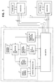
- a simplified ATM network which represents one of a plurality of peer groups.
- the network comprises ATM nodes 1, 2 and 3 interconnected by physical links.
- nodes 1 and 2 are interconnected by three links 6, nodes 1 and 3 being interconnected by two links 7 and nodes 2 and 3 being interconnected by a single link 8.
- Each node includes an ATM switch 4 and a microprocessor-based controller 5.
- the controller 5 In order to implement source routing where the source node is responsible for selecting the path to the destination, the controller 5 first obtains its local knowledge of the network topology by exchanging link state parameters (which describe the characteristics of logical links) with other ATM nodes via the respective ATM switch 4. Nodes in the ATM network are organized into peer groups (domains).
- Links that connect the members of the same group are "horizontal" links and links that connect two peer groups are “outside” links.
- Peer groups are organized into different hierarchical levels in parent/child relationship.
- the ATM nodes shown in Fig. 1 are members of the same peer group.
- nodes In the ATM network, nodes first discover each other through a PNNI (private network-network interface) hello protocol by exchanging control messages over a horizontal link with their immediate neighbor nodes.
- the discovery process of each node is performed by a hello protocol unit 10 by sending its own node identifier, port number and peer group identifier. If two neighbors discover that they are within the same peer group by comparison of their peer group identifiers, they exchange their node identifier and their port number to which the horizontal link being used is attached so that each node obtains the remote port number of the horizontal link.
- the internodal link information of the node may be obtained and stored in an internodal link memory 11 as illustrated in Fig. 2.
- This hello protocol procedure is performed at regular intervals to update the contents of internodal link memory 11. If two nodes discover each other across an outside link that they have different peer group identifiers, they identify themselves as a border node of the respective peer group and determine that the outside link is an uplink to a parent peer group.
- resource vectors of a set of physical links are aggregated (or summarized) into a single resource vector of a single logical link, using an aggregation parameter "r" as a measure of aggregation.
- the resource vectors are represented by quality of service (QOS) vectors as will be described later.
- QOS quality of service
- an aggregation parameter is obtained through a negotiation process by exchanging default values between immediate nodes through an aggregation parameter negotiation unit 12.
- the aggregation parameter "r" is in the range between 0 (which is referred to as conservative aggregation) and 1 (which is referred to as aggressive aggregation).
- Fig. 3 One example of this negotiation process is illustrated in Fig. 3.
- node A asserts a default value 1, node B asserting a default value 0.5.
- Node A recognizes that node B has asserted a lower value and concedes to 0.5, while node B, recognizing that it has asserted a lower value, adopts its own value as an agreed-upon parameter.
- the default values of a node may be determined by the network management personnel of the node by reflecting the various QOS parameters of the links through which the node is connected to its immediate neighbor nodes, and an optimum negotiation algorithm may be determined by the operating policy of the network. In the illustrated example, the algorithm is to choose a lower default value.
- a link aggregation unit 13 performs a link aggregation of multiple sets of local and remote port numbers of parallel physical links to an immediate neighbor into a single set of local and remote port numbers of a logical link according to network resources (available bandwidths and delays of physical links) stored in a resource manager 24 as shown in Fig. 3.
- the link aggregation unit 13 performs a QOS aggregation of the QOS vectors of the physical links into a single QOS vector of a logical link using the negotiated aggregation parameter "r" in a manner to be described below and stores the QOS vectors of logical links (as well as the QOS vectors or physical links) into a local resource database 15, as illustrated in Fig. 4.
- the link resource information stored in the database 15 is updated at regular intervals with varying resource of the node by the resource manager 14.
- non-additive metrics such as maximum cell rate (constant bit rate) and available cell rate (real-time variable bit rate)
- additive metrics such as cell delay variation (non real time variable bit rate), cell transfer delay
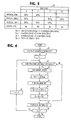
- the aggregation process begins with the mapping of physical links 1, 2, 3 to QOS metrics QOS 1 to QOS 8 of classes A, B, C and D, for example, in an aggregation table 20 as shown in Fig. 5.
- the aggregation process then proceeds to determine the metrics of the different QOS classes for a logical link to which the physical links are to be aggregated.
- the QOS metric values are aggregated as follows to obtain a resource vector (Q a , Q b , Q c , Q d ) for the logical link, where,
- the flowchart of Fig. 6 illustrates the QOS aggregation process.
- the process begins with reception of the aggregation parameter "r" from the negotiation unit 12 (step 30).
- a QOS-class identifying variable "i" is set to 1 (step 31) and a search is made through the aggregation table 30 to determine whether there is more than one class-i QOS metric for a set of physical links (step 32). If the decision is affirmative at step 42, flow proceeds to step 33 to find a maximum value of the class-i QOS metrics and multiplies it with the parameter "r" to produce Q 1 at step 34.
- a minimum value of the class-i QOS metrics is determined, and at step 36, it is multiplied with (1 - r) to produce Q 2 .
- Q 1 and Q 2 are summed to produce an aggregated QOS metric Q i for class 'i", which is stored in the aggregation table 20 (step 39).
- Flow proceeds to step 40 to check to see if i is equal to k (where k is the maximum number of QOS classes). If i is smaller than k, flow proceeds to step 31 to increment the variable i by one and returns to step 32 to repeat the same process on the next QOS class. If the decision at step 32 is negative, flow proceeds to step 40, skipping steps 33 to 37.
- a routing protocol unit 16 monitors the contents of the local resource database 15 to determine whether there is an update in any of the aggregated QOS values which exceeds a predefined threshold. Thus, when the database 15 is initially created or when there is a significant amount of updates in the local resource database 15, each node uses its routing protocol unit 16 to advertise its current topology information to other nodes. The routing protocol unit 16 also receives topology information from other nodes and builds a remote resource database 17, and uses the contents of local and remote resource databases 15 and 17 to provide route calculations.
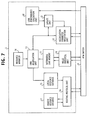
- Controller 5 is modified as shown in Fig. 7. This modification differs from the previous embodiment in that the controller 5 additionally includes a link performance evaluation unit 50 and an aggregation parameter update unit 51.
- Link performance evaluation unit 50 is connected to the ATM switch to collect traffic data of a logical link from the network and calculates the call setup failure ratio and utilization efficiency of the logical link at regular intervals to evaluate the performance of the logical link.
- Parameter update unit 51 updates the aggregation parameter "r" if the evaluated performance does not satisfy predefined conditions. As illustrated in Fig.
- Aggregation parameter update unit 51 supplies the updated aggregation parameter via the negotiation unit 12 to the remote node. If two nodes have been settled on an aggregation parameter of 0.5 and the local node updates its parameter to 0.2 and informs the remote node of the new value. If the same negotiation algorithm is used as described previously, the remote node agrees to the new value and informs the local node of its agreement to the new parameter 0.2.
- the negotiation unit 12 feeds the new aggregation parameter to the aggregation unit 13 to cause it to recalculate the QOS values of the logical link stored in the local resource database 15.
- Routing unit 16 monitors the contents of the local resource database 15 and advertises the updated QOS values by flooding control messages across the network if the degree of updates exceeds some predefined value.
- the updated QOS values will then be reflected on the operating performance of the local link, and the altered link performance is measured by the link performance evaluation unit 50.
- a closed-loop feedback control is established and the QOS values of the logical link are converged to optimum values.
- Computer simulations further indicate that the quantity of logical link state information received by control messages flooded across the network during a unit time interval varies as a function of the aggregation parameter. For this reason, the link performance evaluation unit 50 monitors the flooded control messages received from neighbor nodes and calculates the amount of logical link state information generated during a unit time interval.
- Aggregation parameter update unit 51 determines whether the topology data rate is within the range of upper and lower limits. If it is higher than the upper limit, the update unit 51 decrements the aggregation parameter, and if it is lower than the lower limit, the update unit increments the parameter.
- Fig. 9 illustrates a modified controller of the present invention in which physical links are aggregated into more than one logical link and in which like parts are numbered with the same numerals as used in the previous embodiment.
- a link grouping unit 70 is connected to the internodal link memory 11 and the resource manager 14 to group a set of physical links into one or more groups of logical links. If the local node has a greater value of node identifier than that of a remote node to which the physical links are connected, the link grouping unit 70 of the local node has the right to initiate the link grouping by identifying the internodal link information (Fig. 2) of memory 11 according to similarities of the link attributes managed by the resource manager 14.
- Link grouping unit 70 segments the physical links into a plurality of logical links, appends unique link group identifiers to the logical links, respectively, to produce link grouping data. This grouping data is transmitted via a transmit/receive unit 72 to the remote node. When the link grouping unit 70 produces link grouping data itself or receives it from the remote node, it organizes the local and remote port numbers of the physical links into groups as shown in Fig. 10 in a link group memory 71.
- link group memory 71 The information stored in link group memory 71 is used by the link aggregation unit 13 to perform a link aggregation process on each group of logical links.
- the aggregation parameter "r" is produced for each logical link group by negotiation unit 12.
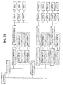
- Link aggregation unit 13 provides the link aggregation process of each logical link group using the aggregation parameter of this group and produces link state data as shown in Fig. 11 to be stored in the local resource database 15.
- Link group performance evaluation unit 50A collects traffic data from the network and identifies the physical links of each group using the port number data stored in memories 11 and 72 and calculates the call setup failure ratio, utilization efficiency and topology data rate of the physical links of each group.
- a connection 80 is provided from the link group performance evaluation unit 50A to the link grouping unit 70 to reflect the evaluated link group performance in the grouping process of unit 70.
- physical links are adaptively converged into optimal groups according to the performance of each link group.
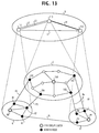
- Fig. 13 shows a plurality of ATM nodes organized into peer groups A, B and C having peer group leaders 90, 94 and 100, respectively.
- These peer groups represent a physical layer and are child peer groups of a common, parent (logical) peer group D representing a logical layer.
- child peer groups A, B and C are represented by logical nodes 111, 112 and 113, respectively.
- peer groups A and B are interconnected by a physical link P1 between border nodes 93 and 95 and this physical link is represented in the parent peer group D as a logical link L1.
- Peer groups A and C are interconnected by physical links P2 and P3 which are represented as logical links L2 and L3 in the parent peer group D, respectively, and nodes 91 and 92 are the border nodes in peer group A that are connected by links P2 and P3 to border nodes 101 and 104 of peer group C.
- peer groups B and C are interconnected by two physical links P4 which are aggregated into and represented by a single logical link L4 in the parent peer group D, and nodes 96 and 97 are the border nodes in peer group B that are connected by links P4 to border nodes 102 and 103 of peer group C.
- Each peer group leader has responsibilities to aggregate nodal and link topology data of its own peer group, exchange the aggregated topology data with the logical nodes of the parent peer group over virtual channels and advertise its topology data to all the child peer groups.
- each peer group leader first approximates a symmetrical star (template) topology by interconnecting its border nodes in a configuration having a nucleus at the center and links (spokes) emanating from the nucleus to ports where the physical links of the peer group are attached, aggregates physical links, and then eliminates one or more spokes where corresponding physical links are aggregated.
- template symmetrical star
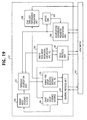
- Each peer group leader includes an ATM switch 140 and a microprocessor-based controller 150.
- Controller 150 comprises a hello protocol unit 201 connected to the ATM switch 140.
- Hello protocol unit 201 exchanges a control message with immediate neighbor nodes of the same peer group as well as with those in the parent peer group to collect nodal and link topology data.
- the control message of the peer group leader includes a plurality of fields containing a local node, a local port number, a local peer group identifier, the number of logical links between peer groups, a logical link group identifier, a local logical port number, a local border node identifier, and a local border port number.
- a physical link (horizontal link) between nodes of the same child peer group is represented by the local and remote node identifiers, the local and remote port numbers and the peer group identifier (domain identifier), and a physical link (outside link) between peer groups is represented by the logical link group identifier, the local and remote logical port numbers, the local and remote border node identifiers, and the local and remote border port identifiers.
- the peer group leader establishes a virtual channel to a remote node, it fills the local port identifier field of the control message with a predefined bit pattern.
- the hello protocol unit 201 When the hello protocol unit 201 has collected topology data from all the immediate neighbor nodes of the same child peer group, it stores the collected data into a child peer group resource database 204. The information collected in this way is similar to that obtained by the hello protocol unit of the previous embodiment. When the hello protocol unit 201 has collected topology data from all the immediate neighbor nodes of the parent peer group, it stores the collected data into a parent peer group internodal link memory 202 in a format as shown in Fig. 15.
- a routing protocol unit 203 exchanges topology data with the rest of the network to collect topology data from nodes other than all the immediate neighbor nodes of the peer group leader and stores the topology data of the child peer groups into the child peer group resource database 204 and the topology data of the parent peer group into a parent peer group resource database 205.
- the routing protocol unit 203 provides route calculations.
- a resource selector 206 is connected to the child peer group resource database 204 to select the resource data of the border nodes of its own peer group and feeds it to a topology aggregation unit 207.
- Topology aggregation unit 207 performs aggregation of the topology data concerning the border nodes of its own peer group in two steps. In the first step, a least cost route is determined for all possible combinations of the border nodes and then their topology is transformed into an intermediate form such as mesh topology. If two least cost routes exist between any two border nodes, the QOS parameters may be taken into account to choose one of the routes as a least cost route.
- Topology aggregation unit 207 of peer group leader 100 for example, transforms the topology of its border nodes 101, 102, 103 and 104 of parent peer group C as represented in Fig. 16A into a meshed topology 160 of Fig.
- border nodes 101, 102, 103 and 104 are represented by ports A1, A2, A3 and A4 of the logical node 113 of Fig. 14 and shown interconnected by links with minimum link costs c ij , where "i" and "j" of a link cost indicate the border nodes between which the link is attached.
- Meshed topology 160 is then transformed into a symmetrical star topology 161 (Fig. 16D) with spokes of equal length (which represents aggregation parameter) "r" from the nucleus N to the respective ports 101 to 104.
- Topology aggregation unit 207 attempts to determine an aggregation parameter vector r i with a "conservative" approach by solving the following equations for both non-additive QOS metrics and additive QOS metrics: Min ⁇ r i (MCR), r j (MCR) ⁇ c ij (MCR) Min ⁇ r i (ACR), r j (ACR) ⁇ c ij (ACR) ( r i (CLR)+ r j (CLR)) ⁇ c ij (CLR) ( r i (CDV)+ r j (CDV)) ⁇ c ij (CDV) ( r i (CTD)+ r j (CTD)) ⁇ c ij (CTD) where
- the advantage of using the mesh topology as an intermediate step is that it significantly reduces the amount of computations which would otherwise be required if the original physical topology were directly converted to the star topology.
- topology aggregation unit 207 For a full understanding of the operation of topology aggregation unit 207, reference is made to the flowchart of Fig. 17.
- the border nodes of a child peer group are initially organized into pairs (step 301) and least link costs c ij are calculated between the nodes of each pair (step 302) as described above, and these nodes are interconnected by the least cost link (step 303). Steps 302 and 303 are repeated until a mesh network topology 160 is formed by the border nodes as illustrated in Fig. 16B (step 304).
- the border nodes are organized into a symmetric star network topology 161 with spokes emanating from the nucleus N to the ports A1 to A4 as shown in Fig. 16B.
- aggregation parameters (or aggregation parameter vector) are determined for all spokes of the star topology according to equations (1), (2), (3) and (4) described above.
- Spokes of the star topology are aggregated, at step 307, according to the aggregation parameters so that an asymmetric star topology 162 is formed as shown in Fig. 16D. It is seen that the spoke from the nucleus to port A3 is aggregated into the spokes to ports A1 and A2 as indicated by the thick lines.
- the least link costs of the mesh topology are recalculated using the aggregation parameters and differences between the initial least link costs and the recalculated least link costs are determined (step 309).
- the maximum value of the differences is detected and compared with a convergence threshold (step 310). If it is not smaller than the convergence threshold, flow proceeds to step 311 to select a link having the maximum difference value and connect it as a bypass link r 12 between ports A1 and A2 to form a star topology 163 as illustrated in Fig. 16E.
- Aggregation parameters and least link costs of the star topology 163 are recalculated at step 312.
- the number of bypass links established in the star topology is compared with a defined maximum number. If it is not greater than the maximum number, flow returns to step 309 to repeat the convergence process again.
- step 310 If it is determined, at step 310, that the differences detected at step 309 are smaller than the convergence threshold or that the number of established bypass links is greater than the maximum number, flow proceeds to step 314.
- the topology aggregation unit 207 looks up the memory 202 and determines whether physical links attached to border nodes of the parent peer group are aggregated. If the decision at step 314 yields a negative answer, flow proceeds to step 317 to save the resource data of the star topology in a parent peer group resource database 205. If physical links P4 between child peer groups B and C have been aggregated into the logical link L4 in the parent peer group D as shown in Fig. 13, the decision at step 314 is affirmative and flow proceeds to step 315 to remove the corresponding port, such as A3, from the star topology 163, forming a star topology 164 as illustrated in Fig. 16F.
- Flow proceeds to step 316 to calculate the QOS values of the links of the star topology 164 to form resource data.
- the resource data of the star topology is saved in the parent peer group resource database 205, and flow advances to the end point of the routine.
- One example of the aggregated topology data stored in database 205 is shown in Fig. 18.
- the controller 150 includes an aggregation/convergence parameter negotiation unit 208 connected to the ATM switch 140.
- Aggregation/convergence parameter negotiation units 208 of two immediate logical nodes exchange convergence parameters such as maximum number of bypass links to be provided in a logical peer group and a convergence threshold value to be used in the convergence process described with reference to Fig. 17.
- Aggregation parameters "r" are exchanged between two nodes in a manner similar to that described in the previous embodiments to determine the aggregation parameter at a point anywhere between aggressive and conservative values.
- Negotiation unit 208 hands over the negotiated aggregation parameter and convergence parameters to the topology aggregation unit 207, where they are used in the routine of Fig. 17.
- the controller 150 may be further provided with a star topology performance evaluation unit 400 and an update unit 401.
- Star topology performance evaluation unit 400 is connected to the ATM switch 140 to collect traffic data from the network at regular intervals.
- Evaluation unit 400 is further connected to the parent peer group resource database 205 to use its topology data (Fig. 18) to identify the traffic data of the aggregated topology of the parent peer group and calculates the call setup failure ratio and network utilization efficiency of all physical links of the parent peer group to evaluate its performance.
- the evaluation data may also be obtained by the peer group leader by having the member nodes of its parent peer group calculate their call setup failure ratio and network utilization efficiency of all of their physical links at regular intervals and collecting them from the member nodes.
- the update unit 401 determines whether the calculated values of call setup failure rate and network efficiency meet specified values and updates the aggregation parameter and/or convergence parameters according to this determination and sets the updated parameter into the aggregation/convergence parameter negotiation unit 209. For example, if the call setup failure ratio is higher than the specified value, the aggregation parameters may be decremented or the convergence threshold is incremented to increase the precision of approximation of the topology aggregation.
- the aggregation parameters are incremented.
- Negotiation unit 208 exchanges the updated parameters with immediate neighbor nodes to agree on negotiated values and hands them over to the topology aggregation unit 207, which then performs the routine of Fig. 17 to produce new star topology data and use it to update the contents of the parent peer group resource database 205.
- Routing protocol unit 203 exchanges the data stored in databases 204 and 205 with all logical nodes and updates the contents of databases 204 and 205. These updates will be reflected in the call setup failure rate and network utilization efficiency of the logical topology and detected again by the evaluation unit 400 to repeat the process to optimize the topology aggregation.
- the link aggregation process of the embodiments of Figs. 1, 7, 9 and 12 can also be used in the embodiments of Figs. 14 and 19 to aggregate multiple physical links.
- the items of performance to be evaluated for optimization may include the rate of crankback messages since the high aggregation parameter causes an increase in the rate of the crankback messages.
Landscapes
- Engineering & Computer Science (AREA)
- Computer Networks & Wireless Communication (AREA)
- Signal Processing (AREA)
- Quality & Reliability (AREA)
- Data Exchanges In Wide-Area Networks (AREA)
- Multi Processors (AREA)
Abstract
Description
where,
- Qa
- = r · max{QOS1, QOS3, QOS6} + (1-r)min{QOS1, QOS3, QOS6}
- Qb
- = r · max{QOS2, QOS7} + (1 - r) min{QOS2, QOS7}
- Qc
- = r · max{QOS4, QOS8} + (1 - r) min{QOS4, QOS8}
- Qd
- = r · QOS5 + (1 - r) QOS5 = QOS5
- MCR
- = maximum cell rate,
- ACR
- = available cell rate,
- CLR
- = cell loss rate,
- CDV
- = cell delay variation, and
- CTD
- = cell transfer delay.
Claims (38)
- A network node for a communication network in which said node is one of a plurality of network nodes, the network node comprising:negotiating means for exchanging aggregation parameters with a neighbor node to agree on a negotiated aggregation parameter;link aggregating means for aggregating a plurality of physical links between the network node and a neighbor node into a logical link according to the negotiated aggregation parameter;a database for storing resource data of said logical link; andmeans for exchanging the resource data with said neighbor node and updating contents of said database with resource data of said neighbor node.
- The network node of claim 1, wherein said plurality of network nodes are divided into a plurality of peer groups, and said neighbor node shares one of said peer groups in common with said network node.
- The network node of claim 1 or 2, wherein each of said physical links is represented by a resource vector and each element of the vector is represented by a resource value of a different resource class, and wherein said logical link is represented by a resource vector and each element of the vector is represented by a sum of a maximum resource value, multiplied by the aggregation parameter, of the elements of the resource vectors of the physical links and a minimum resource value, multiplied by unity minus the aggregation parameter, of the elements of the resource vectors of the physical links.
- The network node of claim 1 or 2, wherein each of said physical links is represented by a resource vector and each element of the vector is represented by a quality-of-service value of a different class, and wherein said logical link is represented by a resource vector and each element of the vector is represented by a sum of a maximum quality-of-service value, multiplied by the aggregation parameter, of the elements of the resource vectors of the physical links and a minimum quality-of-service value, multiplied by unity minus the aggregation parameter, of the elements of the resource vectors of the physical links.
- The network node of claim 1, 2, 3 or 4, further comprising:link performance evaluation means for evaluating an operating performance of said logical link by using traffic data from the network; andupdate means for updating the negotiated aggregation parameter according to the detected operating performance,said negotiating means exchanging the updated aggregation parameter with said neighbor node to agree on a negotiated aggregation parameter,said link aggregating means aggregating said physical links into a logical link according to the negotiated aggregation parameter and storing resource data of the logical link into said database.
- The network node of any one of claims 1 to 5, further comprising means for organizing said physical links into a plurality of groups according to similarities of resource classes of said physical links,
said aggregating means aggregating the physical links of each of said groups into a logical link according to the negotiated aggregation parameter and storing resource data of the logical link into said database. - The network node of claim 6, further comprising:link group performance evaluation means for detecting an operating performance of each of said groups of physical links; andupdate means for updating the negotiated aggregation parameter according to the detected operating performance,said negotiating means exchanging the updated aggregation parameter with said neighbor node to agree on a negotiated updated aggregation parameter,said link aggregating means aggregating said physical links of each of said groups into a logical link according to the negotiated updated aggregation parameter and storing resource data representing the logical link into said database.
- A peer group leader node of a peer group in a communication network in which a plurality of interconnected nodes are divided into a plurality of peer groups, each peer group having border nodes via which the peer group is interconnected with other peer groups, comprising:negotiating means for exchanging aggregation parameters with other peer group leader nodes to agree on negotiated aggregation parameters;topology aggregating means for aggregating physical topology of the border nodes of said peer group into a logical star topology using said negotiated aggregation parameters;a database for storing resource data of said logical star topology; androuting means for exchanging the resource data with a neighbor peer group leader node and updating the database with resource data from the neighbor peer group leader node.
- The peer group leader node of claim 8, further comprising:star topology performance evaluation means for evaluating an operating performance of the star topology by using traffic data from the network;update means for updating the negotiated aggregation parameters according to the evaluated operating performance,said negotiating means exchanging the updated aggregation parameters with other peer group leader nodes to agree on negotiated updated aggregation parameters,said topology aggregating means aggregating said physical topology using the negotiated updated aggregation parameters.
- The peer group leader node of claim 8 or 9, wherein said topology aggregating means is arranged to:a) organize the border nodes of the peer group into a predetermined topology,b) calculate initial least costs of links of the topology,c) organize said border nodes into a star topology in which the border nodes are represented as a nucleus and ports,d) determine aggregation parameters for links of the star topology using said initial least costs,e) recalculate second least costs of said predetermined topology using the aggregation parameters,f) aggregate physical links between said nucleus and said ports into logical links according to said aggregation parameter,g) determine a plurality of differences between the initial least costs and the second least costs,h) determine a link having a maximum value of said differences if said maximum value is greater than a convergence threshold value, andi) interconnect adjacent ones of said ports with said link bypassing the nucleus.
- The peer group leader node of claim 10, wherein said predetermined topology is a mesh topology.
- The peer group leader node of claim 8, 9, 10 or 11, wherein said topology aggregating means is arranged to:aggregate physical links between two peer groups into a logical link; andremove one of said ports from the scar topology corresponding to one of said physical links.
- The peer group leader node of claim 10, 11 or 12, wherein said negotiating means is further arranged to exchange the convergence threshold value with other peer group leader nodes to agree on a negotiated convergence threshold value,
said topology aggregating means determining said link having a maximum value of said differences if said maximum value is greater than the negotiated convergence threshold value. - A communication network comprising:a plurality of network nodes organized into a plurality of interconnected peer groups, each of said peer groups having a peer group leader node and a plurality of border nodes through which the at least one peer group is connected to other peer groups;each network node comprising:negotiating means for exchanging aggregation parameters with a neighbor node of the same peer group to agree on a negotiated aggregation parameter;link aggregating means for aggregating a plurality of physical links between the network node and a neighbor node into a logical link according to the negotiated aggregation parameter;a database for storing resource data of said logical link; andmeans for exchanging the resource data with said neighbor node and updating contents of said database with resource data of said neighbor node,each group leader node comprising:negotiating means for exchanging aggregation parameters with other peer group leader nodes to agree on negotiated aggregation parameters;topology aggregating means for aggregating physical topology of the border nodes of said peer group into a logical star topology using said negotiated aggregation parameters;a database for scoring resource data of said logical star topology; androuting means for exchanging the resource data with a neighbor peer group leader node and updating the database with resource data from the neighbor peer group leader node.
- The communication network of claim 14, wherein said plurality of network nodes are divided into a plurality of peer groups, and said neighbor node shares one of said peer groups in common with said network node.
- The communication network of claim 14 or 15, wherein each of said physical links is represented by a resource vector and each element of the vector is represented by a resource value of a different resource class, and wherein said logical link is represented by a resource vector and each element of the vector is represented by a sum of a maximum resource value, multiplied by the aggregation parameter, of the elements of the resource vectors of the physical links and a minimum resource value, multiplied by unity minus the aggregation parameter, of the elements of the resource vectors of the physical links.
- The communication network of claim 14 or 15, wherein each of said physical links is represented by a resource vector and each element of the vector is represented by a quality-of-service value of a different class, and wherein said logical link is represented by a resource vector and each element of the vector is represented by a sum of a maximum quality-of-service value, multiplied by the aggregation parameter, of the elements of the resource vectors of the physical links and a minimum quality-of-service value, multiplied by unity minus the aggregation parameter, of the elements of the resource vectors of the physical links.
- The communication network of any one of claims 14 to 17, further comprising:link performance evaluation means for evaluating an operating performance of said logical link by using traffic data from the network; andupdate means for updating the negotiated aggregation parameter according to the detected operating performance,said negotiating means exchanging the updated aggregation parameter with said neighbor node to agree on a negotiated aggregation parameter,said link aggregating means aggregating said physical links into a logical link according to the negotiated aggregation parameter and storing resource data of the logical link into said database.
- The communication network of any one of claims 14 to 18, further comprisingmeans for organizing said physical links into a plurality of groups according to similarities of resource classes of said physical links,said aggregating means aggregating the physical links of each of said groups into a logical link according to the negotiated aggregation parameter and storing resource data of the logical link into said database.
- The communication network of claim 19, further comprising:link group performance evaluation means for detecting an operating performance of each of said groups of physical links; andupdate means for updating the negotiated aggregation parameter according to the detected operating performance,said negotiating means exchanging the updated aggregation parameter with said neighbor node to agree on a negotiated updated aggregation parameter,said link aggregating means aggregating said physical links of each of said groups into a logical link according to the negotiated updated aggregation parameter and scoring resource data representing the logical link into said database.
- The communication network of any one of claims 14 to 20, further comprising:star topology performance evaluation means for evaluating an operating performance of the star topology by using traffic data from the network;update means for updating the negotiated aggregation parameters according to the evaluated operating performance,said negotiating means exchanging the updated aggregation parameters with other peer group leader nodes to agree on negotiated updated aggregation parameters,said topology aggregating means aggregating said physical topology using the negotiated updated aggregation parameters.
- The communication network of any one of claims 14 to 21, wherein said topology aggregating means is arranged toa) organize the border nodes of the peer group into a predetermined topology,b) calculate initial least costs of links of the topology,c) organize said border nodes into a star topology in which the border nodes are represented as a nucleus and ports,d) determine aggregation parameters for links of the star topology using said initial least costs,e) recalculate second least costs of said predetermined topology using the aggregation parameters,f) aggregate physical links between said nucleus and said ports into logical links according to said aggregation parameter,g) determine a plurality of differences between the initial least costs and the second least costs,h) determine a link having a maximum value of said differences if said maximum value is greater than a convergence threshold value, andi) interconnect adjacent ones of said ports with said link bypassing the nucleus.
- The communication network of claim 22, wherein said predetermined topology is a mesh topology.
- The communication network of any one of claims 14 to 23, wherein said topology aggregating means is arranged toaggregate physical links between two peer groups into a logical link; andremove one of said ports from the star topology corresponding to one of said physical links.
- The communication network of claim 22, 23 or 24, wherein said negotiating means is further arranged to exchange the convergence threshold value with other peer group leader nodes to agree on a negotiated convergence threshold value,
said topology aggregating means determining said link having a maximum value of said differences if said maximum value is greater than the negotiated convergence threshold value. - An aggregation method for each of a plurality of nodes of a communication network, the method comprising the steps of:a) exchanging aggregation parameters with a neighbor node to agree on a negotiated aggregation parameter;b) aggregating a plurality of physical links from the node to the neighbor node into a logical link according to the negotiated aggregation parameter and storing resource data of said logical link into a database; andc) exchanging the resource data with said neighbor node and updating contents of said database with resource data of said neighbor node.
- The method of claim 26, wherein each of said physical links is represented by a resource vector and each element of the vector is represented by a resource value of a different resource class, wherein the step (b) comprises the steps of:b1) detecting a maximum resource value and a minimum resource value of an element of the resource vectors of the physical links;b2) multiplying the maximum resource value by the aggregation parameter and multiplying the minimum resource value by unity minus the aggregation parameter; andb3) summing the multiplied maximum resource value and the multiplied minimum resource value; andb4) repeating the steps (b1) to (b3) for each successive element of the resource vectors of the physical links.
- The method of claim 26, wherein each of said physical links is represented by a resource vector and each element of the vector is represented by a quality-of-service value of a different class, wherein the step (b) comprises the steps of:b1) detecting a maximum quality-of-service value and a minimum quality-of-service value of an element of the resource vectors of the physical links;b2) multiplying the maximum quality-of-service value by the aggregation parameter and multiplying the minimum quality-of-service value by unity minus the aggregation parameter; andb3) summing the multiplied maximum quality-of-service value and the multiplied minimum quality-of-service value; andb4) repeating the steps (b1) to (b3) for each successive element of the resource vectors of the physical links.
- An aggregation method for each of a plurality of nodes of a communication network, the method comprising the steps of:a) exchanging aggregation parameters with a neighbor node to agree on a negotiated aggregation parameter;b) aggregating a plurality of physical links from the node to the neighbor node into a logical link according to the negotiated aggregation parameter and storing resource data of said logical link into a database;c) exchanging the resource data with said neighbor node and updating contents of said database with resource data of said neighbor node;d) evaluating an operating performance of said logical link by using traffic data from the network;e) updating the negotiated aggregation parameter according to the detected operating performance;f) exchanging the updated aggregation parameter with said neighbor node to agree on a negotiated aggregation parameter; andg) repeating the steps (b) to (f) using the negotiated aggregation parameter.
- An aggregation method for each of a plurality of nodes of a communication network, the method comprising the steps of:a) organizing a plurality of physical links between the node and a neighbor node into a plurality of groups according to similarities of resource classes of said physical links;b) exchanging an aggregation parameter with the neighbor node to agree on a negotiated aggregation parameter;c) aggregating said physical links into a plurality of said groups of logical links using the negotiated aggregation parameter and storing resource data of said logical link into a database; andd) exchanging the resource data with said neighbor node and updating contents of said database with resource data of said neighbor node.
- An aggregation method for each of a plurality of nodes of a communication network, the method comprising the steps of:a) organizing a plurality of physical links between the node and a neighbor node into a plurality of groups according to similarities of resource classes of said physical links;b) exchanging an aggregation parameter with the neighbor node to agree on a negotiated aggregation parameter;c) aggregating said physical links into a plurality of said groups of logical links using the negotiated aggregation parameter and storing resource data of said logical link into a database;d) exchanging the resource data with said neighbor node and updating contents of said database with resource data of said neighbor node;e) evaluating an operating performance of each of said groups of physical links from traffic data from the network;f) updating the negotiated aggregation parameter according to the evaluated operating performance; andg) repeating the steps (b) to (e) using the updated aggregation parameter as said aggregation parameter.
- An aggregation method for a peer group leader node in a communication network formed by a plurality of interconnected nodes which are divided into a plurality of peer groups, each peer group having said peer group leader node and border nodes via which the peer group is interconnected with other peer groups, the method comprising the steps of:a) exchanging aggregation parameters with other peer group leader nodes to agree on negotiated aggregation parameters;b) aggregating physical topology of the border nodes of said peer group into a logical star topology using said negotiated aggregation parameters and scoring resource data of said logical scar topology in a database; andc) exchanging the resource data with a neighbor peer group leader node and updating the database with resource data from the neighbor peer group leader node.
- The method of claim 32, wherein the step (b) comprises the steps of:b1) organizing the border nodes of said peer group into a predetermined topology;b2) calculating initial least costs of links of the topology;b3) organizing said border nodes into a star topology in which the border nodes are represented as a nucleus and ports;b4) determining aggregation parameters for links of the star topology using said initial least costs;b5) recalculating second least costs of said predetermined topology using the aggregation parameters;b6) aggregating physical links from said nucleus to said ports into logical links according to said aggregation parameter;b7) determining a plurality of differences between the initial least costs and the second least costs;b8) determining a link having a maximum value of said differences if said maximum value is greater than a convergence threshold value; andb9) interconnecting adjacent ones of said ports with the link bypassing the nucleus.
- The method of claim 33, wherein said predetermined topology is a mesh topology.
- The method of claim 33 or 34, further comprising the steps of:aggregating physical links between two peer groups into a logical link; andremoving one of said ports of step (b9) corresponding to one of said physical links.
- The method of claims 33, 34 or 35, further comprising the steps of:following the step (b9), recalculating the aggregation parameters and said second least costs of the links of the predetermined topology; andrepeating the steps (b7) to (b9) until said maximum value becomes smaller than said convergence threshold value.
- The method of any one of claims 32 to 36, further comprising the steps of:evaluating an operating performance of the logical star topology by using traffic data from the network;updating the negotiated aggregation parameters of the step (a) according to the evaluated operating performance; andrepeating the steps (b) and (c).
- The method of any one of claims 33 to 37, further comprising the steps of:evaluating an operating performance of the logical star topology by using traffic data from the network;updating the negotiated aggregation parameters of the step (a) according to the evaluated operating performance;exchanging the negotiated updated aggregation parameters with other peer group leader nodes to agree on negotiated updated aggregation; andrepeating the steps (b5) to (b9).
Applications Claiming Priority (6)
| Application Number | Priority Date | Filing Date | Title |
|---|---|---|---|
| JP12653297 | 1997-04-30 | ||
| JP12653297 | 1997-04-30 | ||
| JP126532/97 | 1997-04-30 | ||
| JP36560797A JP3063721B2 (en) | 1997-04-30 | 1997-12-22 | Topology information exchange device and machine-readable recording medium recording program |
| JP36560797 | 1997-12-22 | ||
| JP365607/97 | 1997-12-22 |
Publications (3)
| Publication Number | Publication Date |
|---|---|
| EP0876076A2 true EP0876076A2 (en) | 1998-11-04 |
| EP0876076A3 EP0876076A3 (en) | 2001-01-24 |
| EP0876076B1 EP0876076B1 (en) | 2008-09-10 |
Family
ID=26462704
Family Applications (1)
| Application Number | Title | Priority Date | Filing Date |
|---|---|---|---|
| EP19980107852 Expired - Lifetime EP0876076B1 (en) | 1997-04-30 | 1998-04-29 | Topology aggregation using parameter obtained by internodal negotiation |
Country Status (5)
| Country | Link |
|---|---|
| US (1) | US6385201B1 (en) |
| EP (1) | EP0876076B1 (en) |
| JP (1) | JP3063721B2 (en) |
| CA (1) | CA2236384C (en) |
| DE (1) | DE69839980D1 (en) |
Cited By (15)
| Publication number | Priority date | Publication date | Assignee | Title |
|---|---|---|---|---|
| EP1135000A1 (en) * | 2000-03-17 | 2001-09-19 | Telefonaktiebolaget Lm Ericsson | Link aggregation |
| GB2371706A (en) * | 2001-01-30 | 2002-07-31 | 3Com Corp | Link aggregation control for network devices |
| EP1411687A2 (en) | 2002-10-07 | 2004-04-21 | Nippon Telegraph and Telephone Corporation | Layered network node |
| WO2004062313A1 (en) * | 2002-12-24 | 2004-07-22 | Intel Corporation | Method and apparatus for data and control packet scheduling in wdm photonic burst-switched networks |
| EP1137228A3 (en) * | 2000-03-24 | 2004-10-27 | Nec Corporation | Link state routing techniques |
| EP1216540A4 (en) * | 1999-09-06 | 2005-01-05 | Cit Alcatel | RECURSIVE IP / DATA NETWORK MODULE FOR TRANSPORT DISTRIBUTION |
| US7266295B2 (en) | 2003-04-17 | 2007-09-04 | Intel Corporation | Modular reconfigurable multi-server system and method for high-speed networking within photonic burst-switched network |
| US7272310B2 (en) | 2003-06-24 | 2007-09-18 | Intel Corporation | Generic multi-protocol label switching (GMPLS)-based label space architecture for optical switched networks |
| US7310480B2 (en) | 2003-06-18 | 2007-12-18 | Intel Corporation | Adaptive framework for closed-loop protocols over photonic burst switched networks |
| US7428383B2 (en) | 2003-02-28 | 2008-09-23 | Intel Corporation | Architecture, method and system of WDM-based photonic burst switched networks |
| US7526202B2 (en) | 2003-05-19 | 2009-04-28 | Intel Corporation | Architecture and method for framing optical control and data bursts within optical transport unit structures in photonic burst-switched networks |
| US7848649B2 (en) | 2003-02-28 | 2010-12-07 | Intel Corporation | Method and system to frame and format optical control and data bursts in WDM-based photonic burst switched networks |
| US8660427B2 (en) | 2002-09-13 | 2014-02-25 | Intel Corporation | Method and apparatus of the architecture and operation of control processing unit in wavelenght-division-multiplexed photonic burst-switched networks |
| EP3217607A1 (en) * | 2016-03-11 | 2017-09-13 | Aruba Networks, Inc. | Configuration of communication interfaces for link aggregation |
| EP4221006A4 (en) * | 2020-11-04 | 2024-05-15 | Huawei Technologies Co., Ltd. | TOPOLOGY INFORMATION PUBLISHING METHOD, NETWORK TOPOLOGY COLLECTION METHOD AND DEVICE |
Families Citing this family (126)
| Publication number | Priority date | Publication date | Assignee | Title |
|---|---|---|---|---|
| US5978379A (en) | 1997-01-23 | 1999-11-02 | Gadzoox Networks, Inc. | Fiber channel learning bridge, learning half bridge, and protocol |
| US6847614B2 (en) * | 1998-04-20 | 2005-01-25 | Broadcom Corporation | Apparatus and method for unilateral topology discovery in network management |
| JP3576811B2 (en) * | 1998-05-22 | 2004-10-13 | 日本電気株式会社 | QoS management device |
| DE69840809D1 (en) * | 1998-09-05 | 2009-06-18 | Ibm | Method for generating the optimal complex PNNI node representations with respect to limited costs |
| CA2285101A1 (en) * | 1998-10-08 | 2000-04-08 | Wayne D. Grover | Integrated ring-mesh network |
| US7430171B2 (en) | 1998-11-19 | 2008-09-30 | Broadcom Corporation | Fibre channel arbitrated loop bufferless switch circuitry to increase bandwidth without significant increase in cost |
| US6633570B1 (en) * | 1999-02-08 | 2003-10-14 | Paitalk Holdings, Inc. | Efficient transmission of data to multiple network nodes |
| JP2000253053A (en) * | 1999-02-25 | 2000-09-14 | Hitachi Ltd | Network system |
| JP3343906B2 (en) * | 1999-03-02 | 2002-11-11 | 日本電気株式会社 | Lightwave network |
| US6874022B1 (en) * | 1999-03-12 | 2005-03-29 | Cisco Technology, Inc. | Method and system for modeling behavior of elements in a telecommunications system |
| US6631141B1 (en) * | 1999-05-27 | 2003-10-07 | Ibm Corporation | Methods, systems and computer program products for selecting an aggregator interface |
| US6876991B1 (en) | 1999-11-08 | 2005-04-05 | Collaborative Decision Platforms, Llc. | System, method and computer program product for a collaborative decision platform |
| US6697334B1 (en) * | 2000-01-18 | 2004-02-24 | At&T Corp. | Method for designing a network |
| US6662174B2 (en) * | 2000-04-17 | 2003-12-09 | Brio Software, Inc. | Analytical server including metrics engine |
| US6941311B2 (en) * | 2000-04-27 | 2005-09-06 | Hyperion Solutions Corporation | Aggregate navigation system |
| US6748394B2 (en) * | 2000-04-27 | 2004-06-08 | Hyperion Solutions Corporation | Graphical user interface for relational database |
| US7167859B2 (en) * | 2000-04-27 | 2007-01-23 | Hyperion Solutions Corporation | Database security |
| US7080090B2 (en) * | 2000-04-27 | 2006-07-18 | Hyperion Solutions Corporation | Allocation measures and metric calculations in star schema multi-dimensional data warehouse |
| US6732115B2 (en) * | 2000-04-27 | 2004-05-04 | Hyperion Solutions Corporation | Chameleon measure and metric calculation |
| US7072897B2 (en) * | 2000-04-27 | 2006-07-04 | Hyperion Solutions Corporation | Non-additive measures and metric calculation |
| JP4530481B2 (en) * | 2000-05-25 | 2010-08-25 | 富士通株式会社 | Communication system and communication apparatus |
| US6718384B2 (en) * | 2000-08-09 | 2004-04-06 | Fujitsu Network Communications, Inc. | System and method for monitoring and maintaining a communication network |
| US7023797B2 (en) * | 2000-12-30 | 2006-04-04 | Intel Corporation | Flexible aggregation of output links |
| AU2002234258A1 (en) * | 2001-01-22 | 2002-07-30 | Sun Microsystems, Inc. | Peer-to-peer network computing platform |
| AT4497U3 (en) * | 2001-03-28 | 2001-12-27 | Avl List Gmbh | METHOD FOR ANALYZING AND EVALUATING MEASURED VALUES OF AN OPEN TEST SYSTEM |
| WO2002087172A1 (en) * | 2001-04-20 | 2002-10-31 | Motorola, Inc. | Protocol and structure for self-organizing network |
| US20020162109A1 (en) * | 2001-04-26 | 2002-10-31 | Koninklijke Philips Electronics N.V. | Distributed storage on a P2P network architecture |
| US7251222B2 (en) * | 2001-05-15 | 2007-07-31 | Motorola, Inc. | Procedures for merging the mediation device protocol with a network layer protocol |
| FR2825270B1 (en) * | 2001-05-31 | 2003-08-08 | Oreal | COMPOSITION OF AEROSOL CONTAINING SILICATE PARTICLES AND SURFACTANTS |
| WO2003001333A2 (en) * | 2001-06-20 | 2003-01-03 | Arbor Networks, Inc., | Detecting network misuse |
| US7062274B2 (en) * | 2001-06-21 | 2006-06-13 | Microsoft Corporation | Increasing the level of automation when establishing and managing network connections |
| US7212534B2 (en) | 2001-07-23 | 2007-05-01 | Broadcom Corporation | Flow based congestion control |
| ATE418198T1 (en) * | 2001-09-04 | 2009-01-15 | Rumi Sheryar Gonda | METHOD FOR SUPPORTING SDH/SONET-APS ON ETHERNET |
| KR100411595B1 (en) * | 2001-12-24 | 2003-12-18 | 엘지전자 주식회사 | Method For Aggregating Link Information In The Private Network To Network Interface |
| US7194002B2 (en) * | 2002-02-01 | 2007-03-20 | Microsoft Corporation | Peer-to-peer based network performance measurement and analysis system and method for large scale networks |
| US7133368B2 (en) * | 2002-02-01 | 2006-11-07 | Microsoft Corporation | Peer-to-peer method of quality of service (QoS) probing and analysis and infrastructure employing same |
| US7072304B2 (en) * | 2002-02-27 | 2006-07-04 | Nortel Networks Limited | Network path selection based on bandwidth |
| US7295555B2 (en) | 2002-03-08 | 2007-11-13 | Broadcom Corporation | System and method for identifying upper layer protocol message boundaries |
| JP3823867B2 (en) * | 2002-04-11 | 2006-09-20 | 日本電気株式会社 | Communication network control system, control method, node and program |
| US7764617B2 (en) * | 2002-04-29 | 2010-07-27 | Harris Corporation | Mobile ad-hoc network and methods for performing functions therein based upon weighted quality of service metrics |
| DE10230688A1 (en) * | 2002-07-08 | 2004-02-05 | Siemens Ag | Communication network with communication components with client and server functionalities and with search functions |
| JP4039158B2 (en) * | 2002-07-22 | 2008-01-30 | ソニー株式会社 | Information processing apparatus and method, information processing system, recording medium, and program |
| US7934021B2 (en) | 2002-08-29 | 2011-04-26 | Broadcom Corporation | System and method for network interfacing |
| US7411959B2 (en) | 2002-08-30 | 2008-08-12 | Broadcom Corporation | System and method for handling out-of-order frames |
| US7346701B2 (en) | 2002-08-30 | 2008-03-18 | Broadcom Corporation | System and method for TCP offload |
| US7355984B1 (en) * | 2002-08-30 | 2008-04-08 | Cisco Technology, Inc. | Method and system for finding network neighbor information |
| US7313623B2 (en) | 2002-08-30 | 2007-12-25 | Broadcom Corporation | System and method for TCP/IP offload independent of bandwidth delay product |
| US8180928B2 (en) | 2002-08-30 | 2012-05-15 | Broadcom Corporation | Method and system for supporting read operations with CRC for iSCSI and iSCSI chimney |
| US7512703B2 (en) * | 2003-01-31 | 2009-03-31 | Hewlett-Packard Development Company, L.P. | Method of storing data concerning a computer network |
| US7298973B2 (en) | 2003-04-16 | 2007-11-20 | Intel Corporation | Architecture, method and system of multiple high-speed servers to network in WDM based photonic burst-switched networks |
| US7792987B1 (en) * | 2003-04-21 | 2010-09-07 | Juniper Networks, Inc. | Supporting virtual private networks using a first network topology for forwarding and a subset of the first network topology or a smaller topology for signaling |
| US7266296B2 (en) | 2003-06-11 | 2007-09-04 | Intel Corporation | Architecture and method for framing control and data bursts over 10 Gbit Ethernet with and without WAN interface sublayer support |
| US20040267778A1 (en) * | 2003-06-27 | 2004-12-30 | Microsoft Corporation | Media foundation topology application programming interface |
| US7613767B2 (en) * | 2003-07-11 | 2009-11-03 | Microsoft Corporation | Resolving a distributed topology to stream data |
| US7392420B2 (en) * | 2003-09-29 | 2008-06-24 | International Business Machines Corporation | Automated error recovery of a licensed internal code update on a storage controller |
| US7266815B2 (en) * | 2003-09-29 | 2007-09-04 | International Business Machines Corporation | Automated control of a licensed internal code update on a storage controller |
| US7315693B2 (en) | 2003-10-22 | 2008-01-01 | Intel Corporation | Dynamic route discovery for optical switched networks |
| US7340169B2 (en) | 2003-11-13 | 2008-03-04 | Intel Corporation | Dynamic route discovery for optical switched networks using peer routing |
| US7519691B2 (en) * | 2003-12-04 | 2009-04-14 | International Business Machines Corporation | Selective update of console parameters from other consoles |
| US7900140B2 (en) * | 2003-12-08 | 2011-03-01 | Microsoft Corporation | Media processing methods, systems and application program interfaces |
| US7712108B2 (en) * | 2003-12-08 | 2010-05-04 | Microsoft Corporation | Media processing methods, systems and application program interfaces |
| US7733962B2 (en) | 2003-12-08 | 2010-06-08 | Microsoft Corporation | Reconstructed frame caching |
| US7735096B2 (en) * | 2003-12-11 | 2010-06-08 | Microsoft Corporation | Destination application program interfaces |
| US20050132031A1 (en) * | 2003-12-12 | 2005-06-16 | Reiner Sailer | Method and system for measuring status and state of remotely executing programs |
| US7734176B2 (en) | 2003-12-22 | 2010-06-08 | Intel Corporation | Hybrid optical burst switching with fixed time slot architecture |
| US7934159B1 (en) | 2004-02-19 | 2011-04-26 | Microsoft Corporation | Media timeline |
| US7941739B1 (en) | 2004-02-19 | 2011-05-10 | Microsoft Corporation | Timeline source |
| US7664882B2 (en) * | 2004-02-21 | 2010-02-16 | Microsoft Corporation | System and method for accessing multimedia content |
| US7577940B2 (en) * | 2004-03-08 | 2009-08-18 | Microsoft Corporation | Managing topology changes in media applications |
| US7609653B2 (en) * | 2004-03-08 | 2009-10-27 | Microsoft Corporation | Resolving partial media topologies |
| US7669206B2 (en) * | 2004-04-20 | 2010-02-23 | Microsoft Corporation | Dynamic redirection of streaming media between computing devices |
| US7590750B2 (en) | 2004-09-10 | 2009-09-15 | Microsoft Corporation | Systems and methods for multimedia remoting over terminal server connections |
| CN1299451C (en) * | 2004-10-15 | 2007-02-07 | 清华大学 | Distributing topopology polymerization method of wave wavelength route optical network |
| US7675882B2 (en) * | 2005-02-01 | 2010-03-09 | Exs, Inc. | Hierarchical mesh network for wireless access |
| JP4861415B2 (en) | 2005-07-20 | 2012-01-25 | ファイアータイド、インク. | Route optimization for on-demand routing protocols for mesh networks |
| CA2518325C (en) | 2005-09-07 | 2013-01-22 | Les Developpements Angelcare Inc. | Apparatus for forming waste containing packs |
| US7668173B2 (en) * | 2005-12-01 | 2010-02-23 | Azalea Networks | Method and system for an adaptive wireless routing protocol in a mesh network |
| US8130638B2 (en) * | 2006-01-24 | 2012-03-06 | Cisco Technology, Inc. | Method and apparatus to elect ABRs dynamically and intelligently |
| US20070206550A1 (en) * | 2006-03-06 | 2007-09-06 | Interdigital Technology Corporation | Method and apparatus for simultaneously processing data in a wireless communication system |
| EP2008411A1 (en) * | 2006-03-30 | 2008-12-31 | Nokia Corporation | A node |
| US20070248092A1 (en) * | 2006-04-24 | 2007-10-25 | Motorola, Inc. | System and method for efficient traffic distribution in a network |
| US8792497B2 (en) * | 2006-06-05 | 2014-07-29 | Tellabs Operations, Inc. | Method and apparatus for performing link aggregation |
| US7570927B2 (en) * | 2006-06-16 | 2009-08-04 | Motorola, Inc. | Decentralized wireless communication network and method having a plurality of devices |
| US20080049701A1 (en) * | 2006-08-24 | 2008-02-28 | Sbc Knowledge Ventures, L.P. | System and method for calculating a bandwidth requirement between two elements in a communications network |
| GB2455674B (en) * | 2006-09-19 | 2010-10-27 | Firetide Inc | Bonding multiple radios in wireless multi-hop mesh networks |
| US20080304421A1 (en) * | 2007-06-07 | 2008-12-11 | Microsoft Corporation | Internet Latencies Through Prediction Trees |
| JP4877108B2 (en) * | 2007-07-09 | 2012-02-15 | ブラザー工業株式会社 | Network system, information processing apparatus, connection destination introduction apparatus, information processing method, information processing apparatus program, and connection destination introduction apparatus program |
| JP2009111873A (en) * | 2007-10-31 | 2009-05-21 | Yazaki Corp | Communication path management method and communication system |
| US8369332B2 (en) * | 2009-08-21 | 2013-02-05 | Alcatel Lucent | Server-side load balancing using parent-child link aggregation groups |
| US8942170B1 (en) * | 2010-09-08 | 2015-01-27 | Zte (Usa) Inc. | Group identification of wireless communication devices |
| US11544288B2 (en) | 2010-12-23 | 2023-01-03 | Mongodb, Inc. | Systems and methods for managing distributed database deployments |
| US9262462B2 (en) | 2012-07-26 | 2016-02-16 | Mongodb, Inc. | Aggregation framework system architecture and method |
| US10366100B2 (en) | 2012-07-26 | 2019-07-30 | Mongodb, Inc. | Aggregation framework system architecture and method |
| US10262050B2 (en) | 2015-09-25 | 2019-04-16 | Mongodb, Inc. | Distributed database systems and methods with pluggable storage engines |
| US9805108B2 (en) | 2010-12-23 | 2017-10-31 | Mongodb, Inc. | Large distributed database clustering systems and methods |
| US9740762B2 (en) | 2011-04-01 | 2017-08-22 | Mongodb, Inc. | System and method for optimizing data migration in a partitioned database |
| US10346430B2 (en) | 2010-12-23 | 2019-07-09 | Mongodb, Inc. | System and method for determining consensus within a distributed database |
| US10997211B2 (en) | 2010-12-23 | 2021-05-04 | Mongodb, Inc. | Systems and methods for database zone sharding and API integration |
| US10740353B2 (en) | 2010-12-23 | 2020-08-11 | Mongodb, Inc. | Systems and methods for managing distributed database deployments |
| US8572031B2 (en) | 2010-12-23 | 2013-10-29 | Mongodb, Inc. | Method and apparatus for maintaining replica sets |
| US10614098B2 (en) | 2010-12-23 | 2020-04-07 | Mongodb, Inc. | System and method for determining consensus within a distributed database |
| US10977277B2 (en) | 2010-12-23 | 2021-04-13 | Mongodb, Inc. | Systems and methods for database zone sharding and API integration |
| US9881034B2 (en) | 2015-12-15 | 2018-01-30 | Mongodb, Inc. | Systems and methods for automating management of distributed databases |
| US11615115B2 (en) | 2010-12-23 | 2023-03-28 | Mongodb, Inc. | Systems and methods for managing distributed database deployments |
| US10713280B2 (en) | 2010-12-23 | 2020-07-14 | Mongodb, Inc. | Systems and methods for managing distributed database deployments |
| US8996463B2 (en) | 2012-07-26 | 2015-03-31 | Mongodb, Inc. | Aggregation framework system architecture and method |
| JP2012181585A (en) * | 2011-02-28 | 2012-09-20 | Seiko Epson Corp | Device system and chip |
| US9106510B2 (en) * | 2012-04-09 | 2015-08-11 | Cisco Technology, Inc. | Distributed demand matrix computations |
| FR2990585B1 (en) * | 2012-05-09 | 2016-02-05 | Intercloud | DATA TRANSMISSION SYSTEM |
| US8805382B2 (en) * | 2012-07-23 | 2014-08-12 | At&T Intellectual Property I, L.P. | System and method for quality of service in a wireless network environment |
| US11403317B2 (en) | 2012-07-26 | 2022-08-02 | Mongodb, Inc. | Aggregation framework system architecture and method |
| US11544284B2 (en) | 2012-07-26 | 2023-01-03 | Mongodb, Inc. | Aggregation framework system architecture and method |
| US10872095B2 (en) | 2012-07-26 | 2020-12-22 | Mongodb, Inc. | Aggregation framework system architecture and method |
| US9729426B2 (en) * | 2013-01-11 | 2017-08-08 | Riverbed Technology, Inc. | Stitching together partial network topologies |
| US9014219B2 (en) | 2013-01-14 | 2015-04-21 | International Business Machines Corporation | Link aggregation (LAG) information exchange protocol |
| US10397107B2 (en) * | 2013-09-30 | 2019-08-27 | Telefonaktiebolaget Lm Ericsson (Publ) | Method and apparatus of adapting an association of physical resources with a summarized resource |
| WO2015120912A1 (en) * | 2014-02-17 | 2015-08-20 | Telefonaktiebolaget L M Ericsson (Publ) | A method and apparatus for allocating physical resources to a summarized resource |
| US10713275B2 (en) | 2015-07-02 | 2020-07-14 | Mongodb, Inc. | System and method for augmenting consensus election in a distributed database |
| US10423626B2 (en) | 2015-09-25 | 2019-09-24 | Mongodb, Inc. | Systems and methods for data conversion and comparison |
| US10673623B2 (en) | 2015-09-25 | 2020-06-02 | Mongodb, Inc. | Systems and methods for hierarchical key management in encrypted distributed databases |
| US10846411B2 (en) | 2015-09-25 | 2020-11-24 | Mongodb, Inc. | Distributed database systems and methods with encrypted storage engines |
| US10394822B2 (en) | 2015-09-25 | 2019-08-27 | Mongodb, Inc. | Systems and methods for data conversion and comparison |
| US10671496B2 (en) | 2016-05-31 | 2020-06-02 | Mongodb, Inc. | Method and apparatus for reading and writing committed data |
| US10621050B2 (en) | 2016-06-27 | 2020-04-14 | Mongodb, Inc. | Method and apparatus for restoring data from snapshots |
| US10866868B2 (en) | 2017-06-20 | 2020-12-15 | Mongodb, Inc. | Systems and methods for optimization of database operations |
| WO2019045696A1 (en) * | 2017-08-29 | 2019-03-07 | Hitachi, Ltd. | Distributed realtime edge-core analytics with feedback |
Family Cites Families (7)
| Publication number | Priority date | Publication date | Assignee | Title |
|---|---|---|---|---|
| US5402478A (en) * | 1992-07-27 | 1995-03-28 | Codex Corporation | System and method for call-by-call source routing with rule-based fallbacks |
| US5535195A (en) | 1994-05-06 | 1996-07-09 | Motorola, Inc. | Method for efficient aggregation of link metrics |
| JP2723084B2 (en) * | 1995-07-19 | 1998-03-09 | 日本電気株式会社 | Link state routing device |
| JP2723097B2 (en) * | 1995-12-04 | 1998-03-09 | 日本電気株式会社 | QOS routing device |
| US5781529A (en) * | 1996-03-27 | 1998-07-14 | General Datacomm, Inc. | Systems and methods for routing ATM switched virtual circuit calls |
| US5831975A (en) * | 1996-04-04 | 1998-11-03 | Lucent Technologies Inc. | System and method for hierarchical multicast routing in ATM networks |
| US6122283A (en) * | 1996-11-01 | 2000-09-19 | Motorola Inc. | Method for obtaining a lossless compressed aggregation of a communication network |
-
1997
- 1997-12-22 JP JP36560797A patent/JP3063721B2/en not_active Expired - Fee Related
-
1998
- 1998-04-29 CA CA002236384A patent/CA2236384C/en not_active Expired - Fee Related
- 1998-04-29 EP EP19980107852 patent/EP0876076B1/en not_active Expired - Lifetime
- 1998-04-29 DE DE69839980T patent/DE69839980D1/en not_active Expired - Lifetime
- 1998-04-29 US US09/069,121 patent/US6385201B1/en not_active Expired - Lifetime
Cited By (24)
| Publication number | Priority date | Publication date | Assignee | Title |
|---|---|---|---|---|
| EP1216540A4 (en) * | 1999-09-06 | 2005-01-05 | Cit Alcatel | RECURSIVE IP / DATA NETWORK MODULE FOR TRANSPORT DISTRIBUTION |
| EP1135000A1 (en) * | 2000-03-17 | 2001-09-19 | Telefonaktiebolaget Lm Ericsson | Link aggregation |
| US7765321B2 (en) | 2000-03-24 | 2010-07-27 | Nec Corporation | Link state routing techniques |
| EP1137228A3 (en) * | 2000-03-24 | 2004-10-27 | Nec Corporation | Link state routing techniques |
| GB2371706A (en) * | 2001-01-30 | 2002-07-31 | 3Com Corp | Link aggregation control for network devices |
| GB2371706B (en) * | 2001-01-30 | 2003-04-23 | 3Com Corp | Link aggregation control for network devices |
| US6819680B2 (en) | 2001-01-30 | 2004-11-16 | 3Com Corporation | Link aggregation control for network devices |
| US8660427B2 (en) | 2002-09-13 | 2014-02-25 | Intel Corporation | Method and apparatus of the architecture and operation of control processing unit in wavelenght-division-multiplexed photonic burst-switched networks |
| EP2242219A1 (en) | 2002-10-07 | 2010-10-20 | Nippon Telegraph And Telephone Corporation | Layered network node, network incorporating the same, node, and layered network |
| EP1411687A3 (en) * | 2002-10-07 | 2009-11-11 | Nippon Telegraph and Telephone Corporation | Layered network node |
| EP1411687A2 (en) | 2002-10-07 | 2004-04-21 | Nippon Telegraph and Telephone Corporation | Layered network node |
| EP2242217A1 (en) | 2002-10-07 | 2010-10-20 | Nippon Telegraph And Telephone Corporation | Layered network node, network incorporating the same, node, and layered network |
| EP2242218A1 (en) | 2002-10-07 | 2010-10-20 | Nippon Telegraph And Telephone Corporation | Layered network node, network incorporating the same, node, and layered network |
| WO2004062313A1 (en) * | 2002-12-24 | 2004-07-22 | Intel Corporation | Method and apparatus for data and control packet scheduling in wdm photonic burst-switched networks |
| US7483631B2 (en) | 2002-12-24 | 2009-01-27 | Intel Corporation | Method and apparatus of data and control scheduling in wavelength-division-multiplexed photonic burst-switched networks |
| US7428383B2 (en) | 2003-02-28 | 2008-09-23 | Intel Corporation | Architecture, method and system of WDM-based photonic burst switched networks |
| US7848649B2 (en) | 2003-02-28 | 2010-12-07 | Intel Corporation | Method and system to frame and format optical control and data bursts in WDM-based photonic burst switched networks |
| US7266295B2 (en) | 2003-04-17 | 2007-09-04 | Intel Corporation | Modular reconfigurable multi-server system and method for high-speed networking within photonic burst-switched network |
| US7526202B2 (en) | 2003-05-19 | 2009-04-28 | Intel Corporation | Architecture and method for framing optical control and data bursts within optical transport unit structures in photonic burst-switched networks |
| US7310480B2 (en) | 2003-06-18 | 2007-12-18 | Intel Corporation | Adaptive framework for closed-loop protocols over photonic burst switched networks |
| US7272310B2 (en) | 2003-06-24 | 2007-09-18 | Intel Corporation | Generic multi-protocol label switching (GMPLS)-based label space architecture for optical switched networks |
| EP3217607A1 (en) * | 2016-03-11 | 2017-09-13 | Aruba Networks, Inc. | Configuration of communication interfaces for link aggregation |
| US10374895B2 (en) | 2016-03-11 | 2019-08-06 | Hewlett Packard Enterprise Development Lp | Configuration of communication interfaces for link aggregation |
| EP4221006A4 (en) * | 2020-11-04 | 2024-05-15 | Huawei Technologies Co., Ltd. | TOPOLOGY INFORMATION PUBLISHING METHOD, NETWORK TOPOLOGY COLLECTION METHOD AND DEVICE |
Also Published As
| Publication number | Publication date |
|---|---|
| EP0876076B1 (en) | 2008-09-10 |
| CA2236384C (en) | 2002-08-13 |
| CA2236384A1 (en) | 1998-10-30 |
| JP3063721B2 (en) | 2000-07-12 |
| US6385201B1 (en) | 2002-05-07 |
| DE69839980D1 (en) | 2008-10-23 |
| EP0876076A3 (en) | 2001-01-24 |
| JPH1115804A (en) | 1999-01-22 |
Similar Documents
| Publication | Publication Date | Title |
|---|---|---|
| US6385201B1 (en) | Topology aggregation using parameter obtained by internodal negotiation | |
| US6483808B1 (en) | Method of optimizing routing decisions over multiple parameters utilizing fuzzy logic | |
| Chen et al. | An overview of quality of service routing for next-generation high-speed networks: problems and solutions | |
| EP0635958B1 (en) | Design and managing method for communication networks | |
| Iwata et al. | ATM routing algorithms with multiple QoS requirements for multimedia internetworking | |
| US6661797B1 (en) | Quality of service based path selection for connection-oriented networks | |
| Orda | Routing with end-to-end QoS guarantees in broadband networks | |
| US6333918B1 (en) | Method of forming routing data | |
| US5933425A (en) | Source routing for connection-oriented network with repeated call attempts for satisfying user-specified QOS parameters | |
| US6606303B1 (en) | Method and device in a packet switched network | |
| US7065044B2 (en) | Managing congestion and traffic flow by considering the minimization of link utilization values | |
| US5495479A (en) | Method and apparatus for an automatic decomposition of a network topology into a backbone and subareas | |
| JP3115769B2 (en) | How to assign metric values to each link in the network | |
| Gelenbe | Sensible decisions based on QoS | |
| EP1135000A1 (en) | Link aggregation | |
| EP0984655B1 (en) | Method for generating the optimal PNNI complex node representations for restrictive costs | |
| CN115914891B (en) | Data center elastic optical network distance adaptive traffic distribution method and system | |
| Aboelela et al. | Fuzzy multiobjective routing model in B-ISDN | |
| US6731608B2 (en) | Complex node representations in PNNI systems | |
| Aboelela et al. | Fuzzy generalized network approach for solving an optimization model for routing in B‐ISDN | |
| Gutierrez et al. | Multicost routing in max-min fair share networks | |
| Alabbad et al. | Localised credit based QoS routing | |
| Felstaine et al. | On the distribution of routing computation in hierarchical ATM networks | |
| Ghosh et al. | A probabilistic scheme for hierarchical qos routing | |
| KR100418968B1 (en) | Method For Selecting Dynamic Routing Using Routing Table |
Legal Events
| Date | Code | Title | Description |
|---|---|---|---|
| PUAI | Public reference made under article 153(3) epc to a published international application that has entered the european phase |
Free format text: ORIGINAL CODE: 0009012 |
|
| AK | Designated contracting states |
Kind code of ref document: A2 Designated state(s): DE FR GB |
|
| AX | Request for extension of the european patent |
Free format text: AL;LT;LV;MK;RO;SI |
|
| PUAL | Search report despatched |
Free format text: ORIGINAL CODE: 0009013 |
|
| AK | Designated contracting states |
Kind code of ref document: A3 Designated state(s): AT BE CH CY DE DK ES FI FR GB GR IE IT LI LU MC NL PT SE |
|
| AX | Request for extension of the european patent |
Free format text: AL;LT;LV;MK;RO;SI |
|
| 17P | Request for examination filed |
Effective date: 20001213 |
|
| AKX | Designation fees paid |
Free format text: DE FR GB |
|
| 17Q | First examination report despatched |
Effective date: 20061219 |
|
| GRAP | Despatch of communication of intention to grant a patent |
Free format text: ORIGINAL CODE: EPIDOSNIGR1 |
|
| GRAS | Grant fee paid |
Free format text: ORIGINAL CODE: EPIDOSNIGR3 |
|
| GRAA | (expected) grant |
Free format text: ORIGINAL CODE: 0009210 |
|
| AK | Designated contracting states |
Kind code of ref document: B1 Designated state(s): DE FR GB |
|
| REG | Reference to a national code |
Ref country code: GB Ref legal event code: FG4D |
|
| REF | Corresponds to: |
Ref document number: 69839980 Country of ref document: DE Date of ref document: 20081023 Kind code of ref document: P |
|
| PLBE | No opposition filed within time limit |
Free format text: ORIGINAL CODE: 0009261 |
|
| STAA | Information on the status of an ep patent application or granted ep patent |
Free format text: STATUS: NO OPPOSITION FILED WITHIN TIME LIMIT |
|
| 26N | No opposition filed |
Effective date: 20090611 |
|
| PGFP | Annual fee paid to national office [announced via postgrant information from national office to epo] |
Ref country code: GB Payment date: 20130424 Year of fee payment: 16 Ref country code: DE Payment date: 20130508 Year of fee payment: 16 |
|
| PGFP | Annual fee paid to national office [announced via postgrant information from national office to epo] |
Ref country code: FR Payment date: 20130625 Year of fee payment: 16 |
|
| REG | Reference to a national code |
Ref country code: DE Ref legal event code: R119 Ref document number: 69839980 Country of ref document: DE |
|
| GBPC | Gb: european patent ceased through non-payment of renewal fee |
Effective date: 20140429 |
|
| REG | Reference to a national code |
Ref country code: FR Ref legal event code: ST Effective date: 20141231 |
|
| PG25 | Lapsed in a contracting state [announced via postgrant information from national office to epo] |
Ref country code: DE Free format text: LAPSE BECAUSE OF NON-PAYMENT OF DUE FEES Effective date: 20141101 Ref country code: GB Free format text: LAPSE BECAUSE OF NON-PAYMENT OF DUE FEES Effective date: 20140429 |
|
| REG | Reference to a national code |
Ref country code: DE Ref legal event code: R119 Ref document number: 69839980 Country of ref document: DE Effective date: 20141101 |
|
| PG25 | Lapsed in a contracting state [announced via postgrant information from national office to epo] |
Ref country code: FR Free format text: LAPSE BECAUSE OF NON-PAYMENT OF DUE FEES Effective date: 20140430 |