EP0875963A1 - Filtered universal serial bus - Google Patents
Filtered universal serial bus Download PDFInfo
- Publication number
- EP0875963A1 EP0875963A1 EP98107205A EP98107205A EP0875963A1 EP 0875963 A1 EP0875963 A1 EP 0875963A1 EP 98107205 A EP98107205 A EP 98107205A EP 98107205 A EP98107205 A EP 98107205A EP 0875963 A1 EP0875963 A1 EP 0875963A1
- Authority
- EP
- European Patent Office
- Prior art keywords
- section
- receptacle
- conductive
- insulative member
- pwb
- Prior art date
- Legal status (The legal status is an assumption and is not a legal conclusion. Google has not performed a legal analysis and makes no representation as to the accuracy of the status listed.)
- Granted
Links
Images



Classifications
-
- H—ELECTRICITY
- H01—ELECTRIC ELEMENTS
- H01R—ELECTRICALLY-CONDUCTIVE CONNECTIONS; STRUCTURAL ASSOCIATIONS OF A PLURALITY OF MUTUALLY-INSULATED ELECTRICAL CONNECTING ELEMENTS; COUPLING DEVICES; CURRENT COLLECTORS
- H01R13/00—Details of coupling devices of the kinds covered by groups H01R12/70 or H01R24/00 - H01R33/00
- H01R13/66—Structural association with built-in electrical component
- H01R13/719—Structural association with built-in electrical component specially adapted for high frequency, e.g. with filters
- H01R13/7195—Structural association with built-in electrical component specially adapted for high frequency, e.g. with filters with planar filters with openings for contacts
-
- H—ELECTRICITY
- H01—ELECTRIC ELEMENTS
- H01R—ELECTRICALLY-CONDUCTIVE CONNECTIONS; STRUCTURAL ASSOCIATIONS OF A PLURALITY OF MUTUALLY-INSULATED ELECTRICAL CONNECTING ELEMENTS; COUPLING DEVICES; CURRENT COLLECTORS
- H01R12/00—Structural associations of a plurality of mutually-insulated electrical connecting elements, specially adapted for printed circuits, e.g. printed circuit boards [PCB], flat or ribbon cables, or like generally planar structures, e.g. terminal strips, terminal blocks; Coupling devices specially adapted for printed circuits, flat or ribbon cables, or like generally planar structures; Terminals specially adapted for contact with, or insertion into, printed circuits, flat or ribbon cables, or like generally planar structures
- H01R12/70—Coupling devices
- H01R12/71—Coupling devices for rigid printing circuits or like structures
- H01R12/712—Coupling devices for rigid printing circuits or like structures co-operating with the surface of the printed circuit or with a coupling device exclusively provided on the surface of the printed circuit
- H01R12/716—Coupling device provided on the PCB
-
- H—ELECTRICITY
- H01—ELECTRIC ELEMENTS
- H01R—ELECTRICALLY-CONDUCTIVE CONNECTIONS; STRUCTURAL ASSOCIATIONS OF A PLURALITY OF MUTUALLY-INSULATED ELECTRICAL CONNECTING ELEMENTS; COUPLING DEVICES; CURRENT COLLECTORS
- H01R12/00—Structural associations of a plurality of mutually-insulated electrical connecting elements, specially adapted for printed circuits, e.g. printed circuit boards [PCB], flat or ribbon cables, or like generally planar structures, e.g. terminal strips, terminal blocks; Coupling devices specially adapted for printed circuits, flat or ribbon cables, or like generally planar structures; Terminals specially adapted for contact with, or insertion into, printed circuits, flat or ribbon cables, or like generally planar structures
- H01R12/70—Coupling devices
- H01R12/71—Coupling devices for rigid printing circuits or like structures
- H01R12/72—Coupling devices for rigid printing circuits or like structures coupling with the edge of the rigid printed circuits or like structures
- H01R12/722—Coupling devices for rigid printing circuits or like structures coupling with the edge of the rigid printed circuits or like structures coupling devices mounted on the edge of the printed circuits
- H01R12/724—Coupling devices for rigid printing circuits or like structures coupling with the edge of the rigid printed circuits or like structures coupling devices mounted on the edge of the printed circuits containing contact members forming a right angle
Definitions
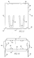
- the conductive shield is shown in greater detail generally at numeral 104.
- This shield includes a top wall 106, a bottom wall 108 and opposed lateral walls 110 and 112.
- the rear shield 98 will preferably be an integral part of the rest of the shield and will be bent downwardly from the top wall 106.
- the top wall includes a front flange 116, a number of rear aperture as at aperture 118 and longitudinal springs 120 and 122 which have respectively convex bends 124 and 126 that bear against the second section of the insulative member.
Landscapes
- Details Of Connecting Devices For Male And Female Coupling (AREA)
- Coupling Device And Connection With Printed Circuit (AREA)
Abstract
Description
Claims (12)
- A receptacle mounted on a printed wiring board (PWB) comprising a concave plug receiving means with a plurality of conductive contacts and a capacitive means fixed to at least one of said conductive contacts.
- The receptacle of claim 1 wherein said receptacle includes an insulative member for supporting the conductive contacts, and preferably wherein the insulative member is at least in part surrounded by a conductive shield.
- The receptacle of claim 1 wherein the sensor means bears against a conductive contact to indicate engagement of the plug with the receptacle, and preferably wherein the conductive contact is a power contact.
- A receptacle adapted to be mounted on a printed wiring board (PWB) comprising an insulative member supporting a plurality of conductive contacts which conductive contacts are terminated to a PWB and a conductive shield having a lower wall superimposed on said PWB and an upper wall superimposed over the insulative member in spaced relation over the lower wall and a pair of side walls perpendicularly interposed between said upper and lower walls to form a plug receiving space between said upper and lower walls and a filtering means which is positioned adjacent one of said conductive contacts.
- The receptacle of claim 4 wherein the conductive contact is a power contact, or wherein the filtering means is a capacitive means, or wherein the filtering means is terminated to the PWB.
- A receptacle adapted to be mounted on a printed wiring board (PWB) comprising:(a) an insulative member comprising a first section extending from a base to an upper side and a second section extending perpendicularly from said vertical section to a terminal edge and said second section having a plurality of longitudinal slots;(b) a plurality of conductive contact means extending first parallel to the second section of the insulative contact in the longitudinal slots and then parallel to the first section of the insulative member;(c) a conductive shielding means having a first side superimposed in spaced relation over the second section of the insulative member and a second side positioned in spaced relation beneath the second section of the insulative member and opposed spaced lateral sides connecting said first and second sides to from a plug receiving cavity between the second side of the second section of the insulative member and a rear side extending perpendicularly from the first side in spaced relation from the first section of the insulative member; and(d) a filtering means interposed between the first section on the insulating means and the rear side of the shielding means.
- The receptacle of claim 6 wherein the filtering means is a capacitive means.
- The receptacle of claim 7 wherein the capacitive means has a plurality of apertures and one of the conductive contact means extends through each of said apertures, and preferably wherein a peripheral conductive ring surrounds each of the apertures in the capacitive means.
- The receptacle of claim 8 wherein each of the conductive rings surrounding the apertures is soldered to the conductive contact passing through the aperture, and preferably wherein there is a ground plane on the capacitive means and each of the conductive rings is electrically connected to the ground plane.
- The receptacle of claim 9 wherein the ground plane is adjacent the rear side of the shielding means and at least one ground spring extends from the rear side of the shielding means to bear the ground plane, and preferably wherein the capacitive means abuts the first section of the insulative member in opposed relation to the ground plane.
- The receptacle of claim 6 wherein the shielding means is comprised of a forward section comprised of the first and second sides and the lateral sides of the shielding means and a rearward section comprised of the rear side of the shielding means, or wherein the conductive contact means are terminated to the PWB.
- The receptacle of claim 7 wherein the capacitive means comprises a signal electrode and a ground plane electrode with a dielectric layer interposed between said electrodes.
Applications Claiming Priority (2)
| Application Number | Priority Date | Filing Date | Title |
|---|---|---|---|
| US08/846,700 US5984725A (en) | 1997-04-30 | 1997-04-30 | Filtered universal serial bus |
| US846700 | 1997-04-30 |
Publications (2)
| Publication Number | Publication Date |
|---|---|
| EP0875963A1 true EP0875963A1 (en) | 1998-11-04 |
| EP0875963B1 EP0875963B1 (en) | 2002-01-30 |
Family
ID=25298692
Family Applications (1)
| Application Number | Title | Priority Date | Filing Date |
|---|---|---|---|
| EP98107205A Expired - Lifetime EP0875963B1 (en) | 1997-04-30 | 1998-04-21 | Filtered universal serial bus |
Country Status (8)
| Country | Link |
|---|---|
| US (2) | US5984725A (en) |
| EP (1) | EP0875963B1 (en) |
| JP (1) | JPH1131558A (en) |
| KR (1) | KR19980081832A (en) |
| CN (1) | CN1201278A (en) |
| DE (1) | DE69803619T2 (en) |
| SG (1) | SG81229A1 (en) |
| TW (1) | TW365474U (en) |
Cited By (2)
| Publication number | Priority date | Publication date | Assignee | Title |
|---|---|---|---|---|
| SG87113A1 (en) * | 1999-05-10 | 2002-03-19 | Molex Inc | Shielded electical connector with ground contact spring |
| EP3544126A4 (en) * | 2016-12-08 | 2019-12-04 | Huawei Technologies Co., Ltd. | DEVICE WITH USB PORT |
Families Citing this family (47)
| Publication number | Priority date | Publication date | Assignee | Title |
|---|---|---|---|---|
| US5984725A (en) | 1997-04-30 | 1999-11-16 | Berg Technology, Inc. | Filtered universal serial bus |
| TW371527U (en) * | 1998-04-13 | 1999-10-01 | Hon Hai Prec Ind Co Ltd | Cable connector |
| TW371520U (en) * | 1998-07-04 | 1999-10-01 | Hon Hai Prec Ind Co Ltd | Shielding electric connector |
| TW405764U (en) * | 1998-10-19 | 2000-09-11 | Molex Inc | Connector supporting device |
| US6256981B1 (en) * | 1999-08-10 | 2001-07-10 | Chrysler Corporation | Fuel control system with multiple oxygen sensors |
| WO2001099237A1 (en) * | 2000-06-20 | 2001-12-27 | Fujitsu Limited | Power supply terminal and backboard |
| USD446773S1 (en) | 2000-09-14 | 2001-08-21 | Hon Hai Precision Ind. Co., Ltd. | Electrical connector |
| TW456592U (en) * | 2000-10-20 | 2001-09-21 | Hon Hai Prec Ind Co Ltd | Socket connector |
| US6431906B1 (en) | 2001-02-28 | 2002-08-13 | Fci Americas Technology, Inc. | Modular connectors with detachable line status indicators |
| US6419523B1 (en) * | 2001-04-04 | 2002-07-16 | Hon Hai Precision Ind. Co., Ltd. | Small form-factor pluggable transceiver cage |
| USD462663S1 (en) | 2001-04-18 | 2002-09-10 | Hosiden Corporation | Electrical connector |
| USD461454S1 (en) | 2001-04-18 | 2002-08-13 | Hosiden Corporation | Electrical connector |
| US6416358B1 (en) * | 2001-04-23 | 2002-07-09 | Molex Incorporated | Shielded electrical connector for mounting on a printed circuit board |
| US6835091B2 (en) * | 2001-07-06 | 2004-12-28 | Fci Americas Technology, Inc. | Universal serial bus electrical connector |
| USD465767S1 (en) | 2001-09-20 | 2002-11-19 | Hon Hai Precision Ind. Co., Ltd. | Electrical connector |
| US6572411B1 (en) | 2001-11-28 | 2003-06-03 | Fci Americas Technology, Inc. | Modular jack with magnetic components |
| TWM250428U (en) * | 2003-10-03 | 2004-11-11 | Advanced Connectek Inc | An improved electrical connector structure |
| CN2674672Y (en) * | 2003-12-06 | 2005-01-26 | 富士康(昆山)电脑接插件有限公司 | Power supply connector |
| USD502145S1 (en) * | 2004-04-01 | 2005-02-22 | Cheng Uei Precision Industry Co., Ltd. | Connector |
| USD508679S1 (en) * | 2004-04-01 | 2005-08-23 | Cheng Uei Precision Industry Co., Ltd. | Electrical connector |
| USD502146S1 (en) * | 2004-04-21 | 2005-02-22 | Cheng Uei Precision Industry Co., Ltd. | Receptacle connector |
| USD507538S1 (en) * | 2004-05-07 | 2005-07-19 | Advanced Connection Technology, Inc. | Electrical connector |
| USD507780S1 (en) * | 2004-05-07 | 2005-07-26 | Advanced Connection Technology, Incorporated | Electrical connector |
| US7081017B2 (en) | 2004-07-19 | 2006-07-25 | Fci Americas Technology, Inc. | USB electrical connector |
| USD522968S1 (en) * | 2004-07-28 | 2006-06-13 | Hon Hai Precision Ind. Co., Ltd. | Electrical connector |
| CN2728007Y (en) * | 2004-08-05 | 2005-09-21 | 富士康(昆山)电脑接插件有限公司 | Electric connector |
| CN2757378Y (en) * | 2004-11-25 | 2006-02-08 | 富士康(昆山)电脑接插件有限公司 | Electric connector |
| USD524746S1 (en) * | 2004-12-20 | 2006-07-11 | Cheng Uei Precision Industry Co., Ltd. | Receptacle connector |
| USD527707S1 (en) * | 2004-12-20 | 2006-09-05 | Cheng Uei Precision Industry Co., Ltd. | Receptacle connector |
| TWM276360U (en) * | 2005-04-14 | 2005-09-21 | Advanced Connectek Inc | Improved shell for an electrical connector |
| JP2006324185A (en) * | 2005-05-20 | 2006-11-30 | Union Machinery Co Ltd | Card connector |
| USD522971S1 (en) * | 2005-07-13 | 2006-06-13 | Advanced Connectek, Inc. | Electrical connector |
| TWM290333U (en) * | 2005-11-18 | 2006-05-01 | Advanced Connectek Inc | Sink-board type electric connector |
| TWM289874U (en) * | 2005-11-18 | 2006-04-21 | Inventec Corp | Shielding member |
| USD550161S1 (en) * | 2006-08-09 | 2007-09-04 | Cheng Uei Precision Industry Co., Ltd. | Electrical connector |
| US20080130207A1 (en) * | 2006-12-05 | 2008-06-05 | Methode Electronics, Inc. | USB connector assembly |
| JP2008147077A (en) * | 2006-12-12 | 2008-06-26 | Matsushita Electric Ind Co Ltd | In-vehicle electronic device |
| US7559802B2 (en) * | 2006-12-26 | 2009-07-14 | Hon Hai Precision Ind. Co., Ltd. | Electrical connectors with separated shields |
| US7731511B2 (en) * | 2007-07-17 | 2010-06-08 | Tyco Electronics Corporation | Panel mounted power module |
| TWM332974U (en) * | 2007-11-30 | 2008-05-21 | Advanced Connectek Inc | Electric connecter |
| CN201773960U (en) * | 2008-09-30 | 2011-03-23 | 苹果公司 | Reduced size multi-pin header connector |
| US8157583B1 (en) * | 2010-11-19 | 2012-04-17 | Shyh-Chang Chiu | Tongue grounding structure of connector |
| CN203445352U (en) * | 2013-06-28 | 2014-02-19 | 富士康(昆山)电脑接插件有限公司 | Electric connector |
| DE102015224872A1 (en) * | 2015-12-10 | 2017-06-14 | Te Connectivity Germany Gmbh | Filter assembly for high-voltage connector assembly and high-voltage connector assembly |
| CN107293874A (en) * | 2016-04-11 | 2017-10-24 | 连展科技(深圳)有限公司 | Electric connector for socket |
| US10524367B2 (en) * | 2018-03-28 | 2019-12-31 | Veoneer Us Inc. | Solderless sensor unit with substrate carrier |
| JP7203700B2 (en) * | 2019-07-24 | 2023-01-13 | 株式会社デンソーテン | Connector shield mounting structure |
Citations (4)
| Publication number | Priority date | Publication date | Assignee | Title |
|---|---|---|---|---|
| EP0439147A1 (en) * | 1990-01-25 | 1991-07-31 | Hosiden Corporation | Connector with short circuit and connector assembly |
| US5073130A (en) * | 1989-12-04 | 1991-12-17 | Hosiden Corporation | Electrical Connector |
| EP0467400A1 (en) * | 1990-07-20 | 1992-01-22 | The Whitaker Corporation | Filter and electrical connector with filter |
| US5624277A (en) * | 1995-08-28 | 1997-04-29 | The Whitaker Corporation | Filtered and shielded electrical connector using resilient electrically conductive member |
Family Cites Families (17)
| Publication number | Priority date | Publication date | Assignee | Title |
|---|---|---|---|---|
| NL8800609A (en) * | 1988-03-11 | 1989-10-02 | Du Pont Nederland | CONNECTOR. |
| US5151054A (en) * | 1991-05-22 | 1992-09-29 | Amphenol Corporation | Electrical connector shell and grounding spring therefor |
| US5257950A (en) * | 1991-07-17 | 1993-11-02 | The Whitaker Corporation | Filtered electrical connector |
| US5224878A (en) * | 1992-03-31 | 1993-07-06 | Amp Incorporated | Connector filter with integral surge protection |
| DE9208702U1 (en) * | 1992-06-29 | 1993-10-28 | Siemens AG, 80333 München | Filter connector with shield housing |
| US5415569A (en) * | 1992-10-19 | 1995-05-16 | Molex Incorporated | Filtered electrical connector assembly |
| US5286221A (en) * | 1992-10-19 | 1994-02-15 | Molex Incorporated | Filtered electrical connector assembly |
| US5344342A (en) * | 1993-01-07 | 1994-09-06 | Amphenol Corporation | Filtered VGA connector |
| US5331505A (en) * | 1993-01-08 | 1994-07-19 | Honeywell Inc. | Multi-coplanar capacitor for electrical connector |
| US5397250A (en) * | 1993-04-06 | 1995-03-14 | Amphenol Corporation | Modular jack with filter |
| KR0125129B1 (en) * | 1993-10-08 | 1997-11-28 | 김은영 | Novel acyl-CoA: Cholesterol acyltransferase (ACAT) activity inhibitor and preparation method thereof |
| US5401192A (en) * | 1994-03-28 | 1995-03-28 | Amphenol Corporation | Combination connector |
| US5580279A (en) * | 1994-10-31 | 1996-12-03 | Berg Technology, Inc. | Low cost filtered and shielded electronic connector and method of use |
| US5587884A (en) | 1995-02-06 | 1996-12-24 | The Whitaker Corporation | Electrical connector jack with encapsulated signal conditioning components |
| US5766043A (en) * | 1996-02-29 | 1998-06-16 | Corcom, Inc. | Telephone connector |
| US5755595A (en) * | 1996-06-27 | 1998-05-26 | Whitaker Corporation | Shielded electrical connector |
| US5984725A (en) | 1997-04-30 | 1999-11-16 | Berg Technology, Inc. | Filtered universal serial bus |
-
1997
- 1997-04-30 US US08/846,700 patent/US5984725A/en not_active Expired - Fee Related
-
1998
- 1998-04-01 TW TW087204879U patent/TW365474U/en unknown
- 1998-04-09 SG SG9800829A patent/SG81229A1/en unknown
- 1998-04-21 DE DE69803619T patent/DE69803619T2/en not_active Expired - Fee Related
- 1998-04-21 EP EP98107205A patent/EP0875963B1/en not_active Expired - Lifetime
- 1998-04-29 CN CN98107486A patent/CN1201278A/en active Pending
- 1998-04-29 KR KR19980015334A patent/KR19980081832A/ko not_active Ceased
- 1998-04-30 JP JP10121509A patent/JPH1131558A/en active Pending
-
1999
- 1999-11-16 US US09/440,948 patent/US6183300B1/en not_active Expired - Fee Related
Patent Citations (4)
| Publication number | Priority date | Publication date | Assignee | Title |
|---|---|---|---|---|
| US5073130A (en) * | 1989-12-04 | 1991-12-17 | Hosiden Corporation | Electrical Connector |
| EP0439147A1 (en) * | 1990-01-25 | 1991-07-31 | Hosiden Corporation | Connector with short circuit and connector assembly |
| EP0467400A1 (en) * | 1990-07-20 | 1992-01-22 | The Whitaker Corporation | Filter and electrical connector with filter |
| US5624277A (en) * | 1995-08-28 | 1997-04-29 | The Whitaker Corporation | Filtered and shielded electrical connector using resilient electrically conductive member |
Cited By (3)
| Publication number | Priority date | Publication date | Assignee | Title |
|---|---|---|---|---|
| SG87113A1 (en) * | 1999-05-10 | 2002-03-19 | Molex Inc | Shielded electical connector with ground contact spring |
| EP3544126A4 (en) * | 2016-12-08 | 2019-12-04 | Huawei Technologies Co., Ltd. | DEVICE WITH USB PORT |
| US10997109B2 (en) | 2016-12-08 | 2021-05-04 | Huawei Technologies Co., Ltd. | Device with USB port |
Also Published As
| Publication number | Publication date |
|---|---|
| DE69803619D1 (en) | 2002-03-14 |
| CN1201278A (en) | 1998-12-09 |
| JPH1131558A (en) | 1999-02-02 |
| US6183300B1 (en) | 2001-02-06 |
| KR19980081832A (en) | 1998-11-25 |
| EP0875963B1 (en) | 2002-01-30 |
| SG81229A1 (en) | 2001-06-19 |
| TW365474U (en) | 1999-07-21 |
| DE69803619T2 (en) | 2002-10-24 |
| US5984725A (en) | 1999-11-16 |
Similar Documents
| Publication | Publication Date | Title |
|---|---|---|
| US5984725A (en) | Filtered universal serial bus | |
| US6095837A (en) | Electrical connector with integral sensor device | |
| US5344342A (en) | Filtered VGA connector | |
| US4695115A (en) | Telephone connector with bypass capacitor | |
| US4679013A (en) | Filtered electrical connector | |
| US4521062A (en) | Electrical connector with optional grounding element | |
| US7666030B2 (en) | Electrical connector with ESD protection | |
| US6095865A (en) | Modular jack | |
| US5603639A (en) | Shielded electrical connector | |
| US6089882A (en) | Memory card connector with grounding clip | |
| US8070528B2 (en) | Electrical connector having improved terminals | |
| US5842887A (en) | Connector with improved shielding | |
| EP0543300B1 (en) | Shielded floating electric connector | |
| CA2144704A1 (en) | Combination connector | |
| US6095861A (en) | Multi-receptacle electrical connector | |
| US5755592A (en) | Combined ground strap and board lock for electrical connector assembly | |
| CA2181316A1 (en) | IC Card Connector Shield Grounding | |
| NL8000023A (en) | ELECTRICAL CONNECTION SYSTEM. | |
| WO1998013904A1 (en) | Hybrid grounded and stacked connector assembly with audio jacks | |
| EP0762324A2 (en) | PC card socket connector and PC card with same | |
| US6394846B1 (en) | Electrical connector with separate receptacles using common filter | |
| US6095824A (en) | Electrical connector assembly | |
| US6231393B1 (en) | Electrical connector | |
| GB2205204A (en) | Electrical socket | |
| US5827092A (en) | Filtered electrical adapter and connector |
Legal Events
| Date | Code | Title | Description |
|---|---|---|---|
| PUAI | Public reference made under article 153(3) epc to a published international application that has entered the european phase |
Free format text: ORIGINAL CODE: 0009012 |
|
| AK | Designated contracting states |
Kind code of ref document: A1 Designated state(s): DE FI FR GB IE |
|
| AX | Request for extension of the european patent |
Free format text: AL;LT;LV;MK;RO;SI |
|
| 17P | Request for examination filed |
Effective date: 19990210 |
|
| 17Q | First examination report despatched |
Effective date: 19990520 |
|
| AKX | Designation fees paid |
Free format text: DE FI FR GB IE |
|
| GRAG | Despatch of communication of intention to grant |
Free format text: ORIGINAL CODE: EPIDOS AGRA |
|
| GRAG | Despatch of communication of intention to grant |
Free format text: ORIGINAL CODE: EPIDOS AGRA |
|
| GRAG | Despatch of communication of intention to grant |
Free format text: ORIGINAL CODE: EPIDOS AGRA |
|
| GRAH | Despatch of communication of intention to grant a patent |
Free format text: ORIGINAL CODE: EPIDOS IGRA |
|
| GRAH | Despatch of communication of intention to grant a patent |
Free format text: ORIGINAL CODE: EPIDOS IGRA |
|
| GRAA | (expected) grant |
Free format text: ORIGINAL CODE: 0009210 |
|
| REG | Reference to a national code |
Ref country code: GB Ref legal event code: IF02 |
|
| RAP1 | Party data changed (applicant data changed or rights of an application transferred) |
Owner name: FCI |
|
| AK | Designated contracting states |
Kind code of ref document: B1 Designated state(s): DE FI FR GB IE |
|
| PG25 | Lapsed in a contracting state [announced via postgrant information from national office to epo] |
Ref country code: FI Free format text: LAPSE BECAUSE OF FAILURE TO SUBMIT A TRANSLATION OF THE DESCRIPTION OR TO PAY THE FEE WITHIN THE PRESCRIBED TIME-LIMIT Effective date: 20020130 |
|
| REF | Corresponds to: |
Ref document number: 69803619 Country of ref document: DE Date of ref document: 20020314 |
|
| RAP2 | Party data changed (patent owner data changed or rights of a patent transferred) |
Owner name: FCI |
|
| REG | Reference to a national code |
Ref country code: IE Ref legal event code: FG4D |
|
| PG25 | Lapsed in a contracting state [announced via postgrant information from national office to epo] |
Ref country code: IE Free format text: LAPSE BECAUSE OF NON-PAYMENT OF DUE FEES Effective date: 20020422 |
|
| PG25 | Lapsed in a contracting state [announced via postgrant information from national office to epo] |
Ref country code: GB Free format text: LAPSE BECAUSE OF NON-PAYMENT OF DUE FEES Effective date: 20020430 |
|
| ET | Fr: translation filed | ||
| PG25 | Lapsed in a contracting state [announced via postgrant information from national office to epo] |
Ref country code: DE Free format text: LAPSE BECAUSE OF NON-PAYMENT OF DUE FEES Effective date: 20021101 |
|
| PLBE | No opposition filed within time limit |
Free format text: ORIGINAL CODE: 0009261 |
|
| STAA | Information on the status of an ep patent application or granted ep patent |
Free format text: STATUS: NO OPPOSITION FILED WITHIN TIME LIMIT |
|
| GBPC | Gb: european patent ceased through non-payment of renewal fee |
Effective date: 20020430 |
|
| PG25 | Lapsed in a contracting state [announced via postgrant information from national office to epo] |
Ref country code: FR Free format text: LAPSE BECAUSE OF NON-PAYMENT OF DUE FEES Effective date: 20021231 |
|
| 26N | No opposition filed | ||
| REG | Reference to a national code |
Ref country code: IE Ref legal event code: MM4A |
|
| REG | Reference to a national code |
Ref country code: FR Ref legal event code: ST |