EP0873931A2 - Hydraulic power steering system with noise attenuation - Google Patents
Hydraulic power steering system with noise attenuation Download PDFInfo
- Publication number
- EP0873931A2 EP0873931A2 EP98107515A EP98107515A EP0873931A2 EP 0873931 A2 EP0873931 A2 EP 0873931A2 EP 98107515 A EP98107515 A EP 98107515A EP 98107515 A EP98107515 A EP 98107515A EP 0873931 A2 EP0873931 A2 EP 0873931A2
- Authority
- EP
- European Patent Office
- Prior art keywords
- fluid
- compliant element
- hydraulic
- suction hole
- reservoir
- Prior art date
- Legal status (The legal status is an assumption and is not a legal conclusion. Google has not performed a legal analysis and makes no representation as to the accuracy of the status listed.)
- Withdrawn
Links
- 239000012530 fluid Substances 0.000 claims abstract description 109
- 238000013016 damping Methods 0.000 claims abstract description 10
- 230000002238 attenuated effect Effects 0.000 claims abstract description 9
- 230000004044 response Effects 0.000 claims description 12
- 230000005540 biological transmission Effects 0.000 claims description 6
- 239000006260 foam Substances 0.000 claims description 3
- 230000014759 maintenance of location Effects 0.000 description 28
- 230000007423 decrease Effects 0.000 description 4
- 238000005086 pumping Methods 0.000 description 4
- 239000004593 Epoxy Substances 0.000 description 3
- 229920001821 foam rubber Polymers 0.000 description 3
- 230000003247 decreasing effect Effects 0.000 description 2
- 238000006073 displacement reaction Methods 0.000 description 2
- 230000004048 modification Effects 0.000 description 2
- 238000012986 modification Methods 0.000 description 2
- 230000036961 partial effect Effects 0.000 description 2
- 238000010276 construction Methods 0.000 description 1
- 238000010586 diagram Methods 0.000 description 1
- 230000000694 effects Effects 0.000 description 1
- 229920001971 elastomer Polymers 0.000 description 1
- 239000013536 elastomeric material Substances 0.000 description 1
- 230000002401 inhibitory effect Effects 0.000 description 1
- 239000002184 metal Substances 0.000 description 1
- 239000004033 plastic Substances 0.000 description 1
- 230000001902 propagating effect Effects 0.000 description 1
Images


Classifications
-
- F—MECHANICAL ENGINEERING; LIGHTING; HEATING; WEAPONS; BLASTING
- F04—POSITIVE - DISPLACEMENT MACHINES FOR LIQUIDS; PUMPS FOR LIQUIDS OR ELASTIC FLUIDS
- F04C—ROTARY-PISTON, OR OSCILLATING-PISTON, POSITIVE-DISPLACEMENT MACHINES FOR LIQUIDS; ROTARY-PISTON, OR OSCILLATING-PISTON, POSITIVE-DISPLACEMENT PUMPS
- F04C15/00—Component parts, details or accessories of machines, pumps or pumping installations, not provided for in groups F04C2/00 - F04C14/00
- F04C15/0042—Systems for the equilibration of forces acting on the machines or pump
- F04C15/0049—Equalization of pressure pulses
-
- B—PERFORMING OPERATIONS; TRANSPORTING
- B62—LAND VEHICLES FOR TRAVELLING OTHERWISE THAN ON RAILS
- B62D—MOTOR VEHICLES; TRAILERS
- B62D5/00—Power-assisted or power-driven steering
- B62D5/06—Power-assisted or power-driven steering fluid, i.e. using a pressurised fluid for most or all the force required for steering a vehicle
- B62D5/062—Details, component parts
Definitions
- the present invention relates to a gear pump in which rotating gears convey a flow of hydraulic fluid.
- the hydraulic fluid is drawn into the gear pump through a suction hole.
- the gear teeth cause flow rate fluctuations as they move into and out of meshing engagement between the gears.
- the flow rate fluctuations propagate outward from the suction hole.
- Corresponding fluctuations in the hydraulic fluid pressure can cause noise. Such noise can be especially undesirable when the gear pump is used in a hydraulic power steering system for a vehicle.
- an apparatus comprises a reservoir containing hydraulic fluid, a gear pump with a suction hole, and a hydraulic muffler.
- the gear pump has gears with meshing teeth that convey a flow of hydraulic fluid from the reservoir into the pump through the suction hole.
- the muffler attenuates noise by damping flow rate fluctuations that are caused by the meshing gear teeth.
- the muffler includes a compliant element and a fluid inertia means interposed between the suction hole and the fluid in the reservoir.
- the fluid inertia means responds to the flow rate fluctuations by directing corresponding hydraulic pressure fluctuations to deflect the compliant element. As a result, noise is attenuated upon deflection of the compliant element.
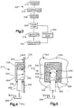
- FIG. 1 An apparatus 10 comprising a first embodiment of the present invention is shown schematically in Fig. 1.
- the apparatus 10 is a vehicle steering system including a hydraulically-assisted rack and pinion steering gear 12.
- the system 10 further includes a hydraulic fluid reservoir 14 and a gear pump 16 for pumping hydraulic fluid from the reservoir 14 to the steering gear 12.
- a hydraulic muffler 18 is interposed between the pump 16 and the reservoir 14.
- the pump 16 has gears with meshing teeth that convey a flow of hydraulic fluid into and through the pump 16.
- the meshing gear teeth cause fluctuations in the flow rate. The fluctuations occur at frequencies that vary with the speed of the rotating gears.
- the muffler 18 functions in a manner analogous to an inductance-capacitance (LC) filter in an electrical circuit. The muffler 18 thus functions to attenuate noise by damping the flow and pressure fluctuations that are caused by the meshing gear teeth in the pump 16.
- LC inductance-capacitance
- the steering gear 12 includes a pinion gear 30 and a piston 32.
- the pinion gear 30 is connected with the input shaft 24 by a torsion bar 34, and is supported for rotation in meshing engagement with a row of rack teeth 36 on the rack 22.
- a tubular section 38 of the lower housing portion 26 functions as a power cylinder.
- the piston 32 is fixed to the rack 22 within the power cylinder 38.
- a pair of variable volume hydraulic fluid chambers 40 and 42 are located in the power cylinder 38 on opposite sides of the piston 32.
- a hydraulic fluid control valve 44 is contained in the upper portion 28 of the housing 20.
- the valve 44 communicates with the first chamber 40 in the power cylinder 38 through a first two-way conduit 46.
- the valve 44 communicates with the second chamber 42 in the power cylinder 38 through a second two-way conduit 48.
- the valve 44 receives hydraulic fluid from the pump 16 through a supply conduit 50.
- a return conduit 52 exhausts hydraulic fluid from the valve 44 to the reservoir 14.
- valve 44 communicates the pump 16 with the first chamber 40 in the power cylinder 38 to pressurize the first chamber 40, and simultaneously communicates the second chamber 42 in the power cylinder 38 with the reservoir 14 to exhaust the second chamber 42.
- a resulting flow of hydraulic fluid from the pump 16, and a resulting hydraulic fluid pressure differential acting across the piston 32, cause the piston 32 and the rack 22 to move to the right, as viewed in Fig. 1. This causes the steering linkage to steer the vehicle wheels in a first direction.
- the input shaft 24 is rotated with the steering wheel in an opposite direction, and is again rotated slightly relative to the pinion gear 30 upon twisting of the torsion bar 34.
- the valve 44 responds by pressurizing the second chamber 42 and by simultaneously exhausting the first chamber 40.
- the piston 32 and the rack 22 then move to the left, as viewed in Fig. 1.
- a resulting follow-up rotation of the pinion gear 30 relative to the input shaft 24 causes the valve 44 again to equalize the hydraulic fluid pressures in the two chambers 40 and 42 in the power cylinder 38.
- the steering gear 12 thus steers the vehicle wheels in directions and amounts corresponding to the directions and the amounts of rotation of the steering wheel and the input shaft 24.
- the steering system 10 is an electric power hydraulic steering (EPHS) system.
- the steering system 10 thus includes an electric motor 60 which drives the pump 16 in response to a predetermined vehicle condition.
- the predetermined vehicle condition in the first embodiment of the present invention is the steering input, as indicated by a torque sensor 62.
- a torque sensor 62 As known in the art, any other suitable vehicle condition, such as vehicle speed, also could be used.
- a controller 64 which may comprise a microprocessor of known construction
- the pump 16 and the reservoir 14 are constructed as adjoining parts of a single unit 66.
- the reservoir 14 has a storage chamber 67 containing hydraulic fluid 68, and has a return port 70 which receives hydraulic fluid from the return conduit 52.
- the pump 16 has a housing 72 with a suction hole 74, an outlet port 76, and a pumping chamber 77.
- the muffler 18 is mounted over the suction hole 74 at the exterior of the pump housing 72, and is contained within the storage chamber 67.
- a pair of gears 78 with meshing gear teeth 80 are supported for rotation in the pumping chamber 77.
- hydraulic fluid is moved through the pumping chamber 77 in the spaces between the gear teeth 80 and the surrounding surfaces 88 of the housing 72.
- a flow of hydraulic fluid is then conveyed through the pump 16 from the suction hole 74 to the outlet port 76 along flow paths extending circumferentially around the gears 78.
- the muffler 18 includes a conduit 90 and a compliant element 92.
- the conduit 90 has an inner end 94 received over the suction hole 74, and has an outer end 96 immersed in the fluid 68 in the storage chamber 67.
- the compliant element 92 is located within a fluid retention cup 98 which is mounted over an aperture 100 in the conduit 90 adjacent to the suction hole 74.
- the retention cup 98 in the first embodiment of the invention is a generally cylindrical part projecting longitudinally from the conduit 90 in a direction perpendicular to the direction in which the hydraulic fluid normally flows past the aperture 100 toward the suction hole 74.
- the conduit 90, the pump housing 72 and the retention cup 98 can be fixed and sealed together in any suitable manner known in the art, such as by the use of epoxy bonds 101.
- the meshing gear teeth 80 cause fluctuations in the hydraulic fluid flow rate. Those fluctuations occur at frequencies that vary with the frequency at which the gear teeth 80 move into and out of meshing engagement at the nip 106 between the gears 78, and then propagate outward from the suction hole 74 at harmonics of the gear tooth frequency. However, such propagation of the flow rate fluctuations is resisted by the inertia of the fluid flowing through the conduit 90 toward the suction hole 74. Accordingly, the inertia of that volume of fluid resists transmission of the flow rate fluctuations from the suction hole 74 to the fluid 68 in the storage chamber 67 in a manner analogous to the inductance L in an electrical LC filter.
- the conduit 90 induces corresponding fluctuations in the fluid pressure at the suction hole 74.
- the conduit 90 inhibits a decreasing flow rate, it induces back pressure at the suction hole 74.
- the back pressure at the suction hole 74 causes a corresponding increase in the pressure acting against the end surface 102 of the compliant element 92.
- the compliant element 92 becomes compressed within the retention cup 98 under the force of the increasing fluid pressure acting against the end surface 102.
- the volume of the retention chamber 104 becomes enlarged by a corresponding amount, and an equal volume of hydraulic fluid flows into the enlarged volume of the retention chamber 104.
- each of the conduits described above is a rigid metal tube.
- Such a structure is preferred for its ability to block pressure fluctuations from propagating radially outward to the surrounding fluid in the reservoir, but a sufficiently rigid plastic tube could be used as an alternative.
- Another alternative conduit structure could comprise a two part casing, with a serpentine channel in one part (formed by valleys and ridges) being sealed by a flat cover plate.
Landscapes
- Engineering & Computer Science (AREA)
- Mechanical Engineering (AREA)
- General Engineering & Computer Science (AREA)
- Chemical & Material Sciences (AREA)
- Combustion & Propulsion (AREA)
- Transportation (AREA)
- Rotary Pumps (AREA)
- Power Steering Mechanism (AREA)
- Fluid-Pressure Circuits (AREA)
Abstract
Description
Claims (10)
- Apparatus comprising:a reservoir containing hydraulic fluid;a gear pump having gears with meshing teeth that convey a flow of hydraulic fluid into said pump through a suction hole; anda hydraulic muffler which attenuates noise by damping flow rate fluctuations caused by said meshing gear teeth;said muffler including a compliant element and a fluid inertia means interposed between said suction hole and said fluid in said reservoir, said fluid inertia means responding to said flow rate fluctuations by directing corresponding hydraulic pressure fluctuations to deflect said compliant element, whereby said noise is attenuated upon deflection of said compliant element.
- Apparatus as defined in claim 1 wherein said fluid inertia means comprises a conduit extending between said suction hole and said fluid in said reservoir so as to inhibit transmission of said flow rate fluctuations from said suction hole to said fluid in said reservoir.
- Apparatus as defined in claim 1 wherein said compliant element defines a movable boundary of a variable volume hydraulic fluid retention chamber which alternately collects and discharges hydraulic fluid in response to said fluctuations in said flow rate.
- Apparatus as defined in claim 1 wherein said reservoir contains said hydraulic fluid in a storage chamber, said muffler also being contained in said storage chamber.
- Apparatus as defined in claim 1 wherein said compliant element is a diaphragm,and/or wherein preferably said compliant element has a structure which is compressible under the force of said hydraulic pressure fluctuations,and/or wherein preferably said structure is a closed cell foam structure,and/or wherein preferably said compliant element extends partially around said suction hole,and/or wherein preferably said compliant element surrounds said suction hole.
- Apparatus comprising:a gear pump having gears with meshing teeth that convey a flow of hydraulic fluid into and through said pump; anda hydraulic muffler which attenuates noise by damping hydraulic flow rate fluctuations caused by said meshing gear teeth;said muffler including a compliant element and fluid inertia means for responding to said flow rate fluctuations by directing corresponding hydraulic pressure fluctuations to deflect said compliant element, whereby said noise is attenuated upon deflection of said compliant element.
- Apparatus as defined in any of the preceding claims wherein said compliant element is a diaphragm,and/or wherein preferably said compliant element has a structure which is compressible under the force of said pressure fluctuations.
- Apparatus comprising:a reservoir containing hydraulic fluid;a hydraulic power steering gear including a hydraulic fluid control valve;a gear pump which pumps hydraulic fluid from said reservoir to said valve, said gear pump having gears with meshing teeth that convey a flow of hydraulic fluid into said pump through a suction hole;an electric motor which drives said gear pump;means for operating said motor in response to a predetermined vehicle condition; anda hydraulic muffler which attenuates noise by damping flow rate fluctuations caused by said meshing gear teeth;said muffler including a compliant element and a fluid inertia means for responding to said flow rate fluctuations by directing corresponding hydraulic pressure fluctuations to deflect said compliant element, whereby said noise is attenuated upon deflection of said compliant element.
- Apparatus as defined in any of the preceding claims wherein said fluid inertia means comprises a conduit extending between said suction hole and said fluid in said reservoir so as to inhibit transmission of said flow rate fluctuations from said suction hole in said fluid in said reservoir,and/or wherein preferably said compliant element defines a movable boundary of a variable volume hydraulic fluid retention chamber which alternately collects and discharges hydraulic fluid in response to said fluctuations in said flow rate,and/or wherein preferably said reservoir contains said hydraulic fluid in a storage chamber, said muffler also being contained in said storage chamber.
- Apparatus comprising:a reservoir containing hydraulic fluid;a gear pump ; anda hydraulic mufflersaid muffler including a compliant element and a fluid inertia means interposed between said suction hole and said fluid in said reservoir.
Applications Claiming Priority (2)
| Application Number | Priority Date | Filing Date | Title |
|---|---|---|---|
| US08/847,571 US5961309A (en) | 1997-04-24 | 1997-04-24 | Gear pump with noise attenuation |
| US847571 | 1997-04-24 |
Publications (2)
| Publication Number | Publication Date |
|---|---|
| EP0873931A2 true EP0873931A2 (en) | 1998-10-28 |
| EP0873931A3 EP0873931A3 (en) | 2000-09-13 |
Family
ID=25300953
Family Applications (1)
| Application Number | Title | Priority Date | Filing Date |
|---|---|---|---|
| EP98107515A Withdrawn EP0873931A3 (en) | 1997-04-24 | 1998-04-24 | Hydraulic power steering system with noise attenuation |
Country Status (5)
| Country | Link |
|---|---|
| US (1) | US5961309A (en) |
| EP (1) | EP0873931A3 (en) |
| JP (1) | JP2960049B2 (en) |
| AU (1) | AU695369B1 (en) |
| BR (1) | BR9801458A (en) |
Cited By (3)
| Publication number | Priority date | Publication date | Assignee | Title |
|---|---|---|---|---|
| EP1004772A3 (en) * | 1998-11-23 | 2002-07-17 | Trw Inc. | Pump having muffler |
| FR2903459A1 (en) * | 2006-07-05 | 2008-01-11 | Jtekt Hpi Soc Par Actions Simp | GEAR PUMP COMPRISING A HYDRAULIC FLUID SUCTION PULSATION DAMPING DEVICE |
| CN109267808A (en) * | 2018-10-31 | 2019-01-25 | 同济大学 | It tunes liquid-type and is used to appearance system |
Families Citing this family (17)
| Publication number | Priority date | Publication date | Assignee | Title |
|---|---|---|---|---|
| US6382033B1 (en) * | 1997-10-09 | 2002-05-07 | Krohne Mebtechnik Gmbh & Co. Kg | Sound damper for ultrasonic waves |
| US6309187B1 (en) * | 1999-03-17 | 2001-10-30 | Visteon Global Technologies, Inc. | Hydraulic gear pump power pack for a power steering system with an integral pressure wave attenuator for fluid noise reduction |
| EP1567497B1 (en) * | 2002-12-06 | 2009-09-23 | Purdue Research Foundation | Pyridines for treating injured mammalian nerve tissue |
| KR20050068909A (en) * | 2003-12-30 | 2005-07-05 | 엘지전자 주식회사 | Apparatus for reducing vibration of reciprocating compressor |
| US20070068302A1 (en) * | 2005-08-23 | 2007-03-29 | O'leary Michael F | Hydraulic active damping system for gears and method |
| US20070201989A1 (en) * | 2005-10-14 | 2007-08-30 | Parker-Hannifin | Low ripple gear pump/motor |
| US8133038B2 (en) * | 2008-12-30 | 2012-03-13 | Samsung Electronics Co., Ltd. | Hermetic compressor |
| US8328741B2 (en) | 2009-09-29 | 2012-12-11 | Covidien Lp | Pneumatic compression garment with noise attenuating means |
| US9572720B2 (en) * | 2009-09-29 | 2017-02-21 | Covidien Lp | Reduced noise pneumatic compression garment |
| US8469910B2 (en) | 2009-09-29 | 2013-06-25 | Covidien Lp | Pneumatic compression garment with noise attenuating means |
| US8491277B2 (en) * | 2010-02-12 | 2013-07-23 | Ebara Corporation | Submersible motor pump, motor pump, and tandem mechanical seal |
| EP3128652B1 (en) * | 2014-03-31 | 2020-03-04 | Guangdong Hua'chan Research Institute of Intelligent Transportation System Co., Ltd. | Shock absorption mechanism of steering motor |
| WO2015149208A1 (en) * | 2014-03-31 | 2015-10-08 | 深圳市智行单轴双轮驱动技术有限公司 | Steering motor |
| CN104976112B (en) * | 2014-04-01 | 2018-12-18 | 松下知识产权经营株式会社 | liquid pump and Rankine cycle device |
| US10465612B2 (en) | 2017-04-03 | 2019-11-05 | Hamilton Sundstrand Corporation | Aircraft fluid control system having a pressure sensor |
| US11619560B2 (en) | 2019-10-18 | 2023-04-04 | Hamilton Sundstrand Corporation | Pressure ripple mitigation in pressure sensors |
| CN112049794B (en) * | 2020-09-15 | 2021-06-04 | 山东绿能环保科技有限公司 | Energy-saving filter residue gear pump |
Family Cites Families (27)
| Publication number | Priority date | Publication date | Assignee | Title |
|---|---|---|---|---|
| US1093151A (en) * | 1913-01-28 | 1914-04-14 | Firm Of Heinrich Lanz | Hydraulic lifting mechanism. |
| DE555154C (en) * | 1929-04-26 | 1932-07-21 | Barmag Barmer Maschf | Control device on rayon spinning pumps |
| US3055307A (en) * | 1959-10-23 | 1962-09-25 | Thompson Ramo Wooldridge Inc | Pressure yoke for pumps |
| US3171359A (en) * | 1963-06-19 | 1965-03-02 | Thompson Ramo Wooldridge Inc | Hydraulically unbalanced wear plate |
| US3360193A (en) * | 1965-12-29 | 1967-12-26 | Rotron Mfg Co | Regenerative compressors with integral mufflers |
| FR2215103A5 (en) * | 1973-01-23 | 1974-08-19 | Hydroperfect Int | |
| US3841804A (en) * | 1973-02-08 | 1974-10-15 | Trw Inc | Floating plate for end clearance seal on gear pumps |
| US3900276A (en) * | 1973-05-16 | 1975-08-19 | Mcculloch Corp | Diaphragm pump method and apparatus |
| DE2513010C3 (en) * | 1975-03-25 | 1980-08-28 | Danfoss A/S, Nordborg (Daenemark) | oil pump for firing systems |
| US4174196A (en) * | 1976-07-28 | 1979-11-13 | Hitachi, Ltd. | Screw fluid machine |
| US4239461A (en) * | 1978-11-06 | 1980-12-16 | Copeland Corporation | Compressor induction system |
| US4330239A (en) * | 1979-10-10 | 1982-05-18 | Tecumseh Products Company | Compressor muffler |
| GB2102074B (en) * | 1981-07-18 | 1985-01-30 | Dowty Group Services | Positive-displacement fluid-machines |
| GB2147256A (en) * | 1983-09-28 | 1985-05-09 | Trw Cam Gears Ltd | Power steering system |
| DE3571586D1 (en) * | 1984-02-15 | 1989-08-24 | Trw Cam Gears Ltd | A power assistance steering system for a vehicle |
| GB2166098B (en) * | 1984-10-31 | 1987-10-28 | Trw Cam Gears Ltd | Vehicle hydraulic servo system |
| US4752195A (en) * | 1985-01-15 | 1988-06-21 | Zahnradfabrik Friedrichshafen, Ag. | Rotary vane type of pump with elongated damping chambers |
| FR2580039B1 (en) * | 1985-03-13 | 1987-06-26 | Bendix France | |
| JPS61286594A (en) * | 1985-06-12 | 1986-12-17 | Hitachi Ltd | Automotive fuel pump device |
| IT1191513B (en) * | 1986-01-10 | 1988-03-23 | Necchi Spa | SILENCER FOR HERMETIC COMPRESSOR |
| DE3850492T2 (en) * | 1987-10-14 | 1995-02-16 | Nestle Sa | SURGICAL IRRIGATION AND SUCTION SYSTEM. |
| FR2681647B1 (en) * | 1991-09-24 | 1995-05-12 | Hydroperfect Int | HYDRAULIC MACHINE OF THE GEAR TYPE WITH FLOATING BODY. |
| DE4328520C2 (en) * | 1993-08-25 | 1997-04-10 | Wap Reinigungssysteme | Vibration dampers for liquids |
| US5401150A (en) * | 1994-02-28 | 1995-03-28 | General Signal Corporation | Noise reduced liquid sealed compressor |
| US5582006A (en) * | 1994-04-29 | 1996-12-10 | Techco Corporation | Method and apparatus for reduction of fluid borne noise in hydraulic systems |
| FR2735534B1 (en) * | 1995-06-15 | 1997-08-29 | Hydroperfect Int | HIGH COMPACTION ELECTRIC MOTOR AND HYDRAULIC PUMP ASSEMBLY |
| FR2738302B1 (en) * | 1995-08-30 | 1997-10-10 | Hydroperfect Int | COMPACT ELECTRO-HYDRAULIC GROUP |
-
1997
- 1997-04-24 US US08/847,571 patent/US5961309A/en not_active Expired - Lifetime
-
1998
- 1998-04-23 AU AU63565/98A patent/AU695369B1/en not_active Ceased
- 1998-04-24 BR BR9801458-7A patent/BR9801458A/en not_active IP Right Cessation
- 1998-04-24 JP JP10114522A patent/JP2960049B2/en not_active Expired - Fee Related
- 1998-04-24 EP EP98107515A patent/EP0873931A3/en not_active Withdrawn
Cited By (3)
| Publication number | Priority date | Publication date | Assignee | Title |
|---|---|---|---|---|
| EP1004772A3 (en) * | 1998-11-23 | 2002-07-17 | Trw Inc. | Pump having muffler |
| FR2903459A1 (en) * | 2006-07-05 | 2008-01-11 | Jtekt Hpi Soc Par Actions Simp | GEAR PUMP COMPRISING A HYDRAULIC FLUID SUCTION PULSATION DAMPING DEVICE |
| CN109267808A (en) * | 2018-10-31 | 2019-01-25 | 同济大学 | It tunes liquid-type and is used to appearance system |
Also Published As
| Publication number | Publication date |
|---|---|
| JPH10324256A (en) | 1998-12-08 |
| EP0873931A3 (en) | 2000-09-13 |
| US5961309A (en) | 1999-10-05 |
| AU695369B1 (en) | 1998-08-13 |
| JP2960049B2 (en) | 1999-10-06 |
| BR9801458A (en) | 2001-09-18 |
Similar Documents
| Publication | Publication Date | Title |
|---|---|---|
| US5961309A (en) | Gear pump with noise attenuation | |
| EP1004772B1 (en) | Pump having muffler | |
| US5582006A (en) | Method and apparatus for reduction of fluid borne noise in hydraulic systems | |
| JPH0392694A (en) | Pressure vibration reducing device | |
| US2601003A (en) | Gear pump | |
| AU2001281230A1 (en) | Energy attenuation apparatus for a system conveying liquid under pressure and method of attenuating energy | |
| WO2002025164A9 (en) | Energy attenuation apparatus for a system conveying liquid under pressure and method of attenuating energy | |
| US7174988B2 (en) | Power steering system | |
| CN107054329A (en) | Brake fluid system | |
| EP2045168A1 (en) | Hydraulic steering system for a vehicle | |
| EP0342848A2 (en) | Power assistance for vehicle steering mechanisms | |
| US20060254850A1 (en) | Power steering system | |
| JP3845547B2 (en) | Power steering device | |
| US7044261B2 (en) | Power steering motor having a noise dampening piston assembly | |
| JPH08232903A (en) | Noise reduction device of fluid pressure device | |
| JP3789215B2 (en) | External gear pump | |
| KR100288342B1 (en) | power steering system for vehicle | |
| JP2007263116A (en) | Rotary pump and brake device including the rotary pump | |
| JP2884005B2 (en) | Power steering device | |
| JP2576193Y2 (en) | Power steering device | |
| JPH06107191A (en) | Power steering device | |
| JPS6320876Y2 (en) | ||
| KR100423229B1 (en) | A Pulse Reduction Power Steering Device Using A Diverging Hose | |
| KR100276712B1 (en) | Power Steering System Using Vacuum Pressure of Engine | |
| EP2034184A2 (en) | Pumping Apparatus |
Legal Events
| Date | Code | Title | Description |
|---|---|---|---|
| PUAI | Public reference made under article 153(3) epc to a published international application that has entered the european phase |
Free format text: ORIGINAL CODE: 0009012 |
|
| AK | Designated contracting states |
Kind code of ref document: A2 Designated state(s): DE ES FR GB IT |
|
| AX | Request for extension of the european patent |
Free format text: AL;LT;LV;MK;RO;SI |
|
| PUAL | Search report despatched |
Free format text: ORIGINAL CODE: 0009013 |
|
| AK | Designated contracting states |
Kind code of ref document: A3 Designated state(s): AT BE CH CY DE DK ES FI FR GB GR IE IT LI LU MC NL PT SE |
|
| AX | Request for extension of the european patent |
Free format text: AL;LT;LV;MK;RO;SI |
|
| 17P | Request for examination filed |
Effective date: 20010208 |
|
| AKX | Designation fees paid |
Free format text: DE ES FR GB IT |
|
| 17Q | First examination report despatched |
Effective date: 20020807 |
|
| RAP1 | Party data changed (applicant data changed or rights of an application transferred) |
Owner name: TRW AUTOMOTIVE U.S. LLC |
|
| STAA | Information on the status of an ep patent application or granted ep patent |
Free format text: STATUS: THE APPLICATION IS DEEMED TO BE WITHDRAWN |
|
| 18D | Application deemed to be withdrawn |
Effective date: 20091031 |