EP0873175B1 - Manifold apparatus for tangential flow filtration apparatus - Google Patents
Manifold apparatus for tangential flow filtration apparatus Download PDFInfo
- Publication number
- EP0873175B1 EP0873175B1 EP96921571A EP96921571A EP0873175B1 EP 0873175 B1 EP0873175 B1 EP 0873175B1 EP 96921571 A EP96921571 A EP 96921571A EP 96921571 A EP96921571 A EP 96921571A EP 0873175 B1 EP0873175 B1 EP 0873175B1
- Authority
- EP
- European Patent Office
- Prior art keywords
- manifold
- filtrate
- fluid communication
- fluid
- outlet
- Prior art date
- Legal status (The legal status is an assumption and is not a legal conclusion. Google has not performed a legal analysis and makes no representation as to the accuracy of the status listed.)
- Expired - Lifetime
Links
- 238000009295 crossflow filtration Methods 0.000 title description 4
- 239000000706 filtrate Substances 0.000 claims description 108
- 239000012530 fluid Substances 0.000 claims description 79
- 239000012465 retentate Substances 0.000 claims description 48
- 238000001914 filtration Methods 0.000 claims description 35
- 230000000694 effects Effects 0.000 claims description 2
- 230000002093 peripheral effect Effects 0.000 claims 5
- 239000007788 liquid Substances 0.000 description 10
- 125000006850 spacer group Chemical group 0.000 description 5
- 230000015572 biosynthetic process Effects 0.000 description 3
- 238000000926 separation method Methods 0.000 description 3
- 238000007789 sealing Methods 0.000 description 2
- 230000000712 assembly Effects 0.000 description 1
- 238000000429 assembly Methods 0.000 description 1
- 230000006835 compression Effects 0.000 description 1
- 238000007906 compression Methods 0.000 description 1
- 239000000470 constituent Substances 0.000 description 1
- 230000001419 dependent effect Effects 0.000 description 1
- 230000014759 maintenance of location Effects 0.000 description 1
- 239000012528 membrane Substances 0.000 description 1
- 238000000034 method Methods 0.000 description 1
Images




Classifications
-
- B—PERFORMING OPERATIONS; TRANSPORTING
- B01—PHYSICAL OR CHEMICAL PROCESSES OR APPARATUS IN GENERAL
- B01D—SEPARATION
- B01D63/00—Apparatus in general for separation processes using semi-permeable membranes
- B01D63/08—Flat membrane modules
- B01D63/082—Flat membrane modules comprising a stack of flat membranes
- B01D63/084—Flat membrane modules comprising a stack of flat membranes at least one flow duct intersecting the membranes
-
- B—PERFORMING OPERATIONS; TRANSPORTING
- B01—PHYSICAL OR CHEMICAL PROCESSES OR APPARATUS IN GENERAL
- B01D—SEPARATION
- B01D63/00—Apparatus in general for separation processes using semi-permeable membranes
- B01D63/08—Flat membrane modules
- B01D63/082—Flat membrane modules comprising a stack of flat membranes
-
- B—PERFORMING OPERATIONS; TRANSPORTING
- B01—PHYSICAL OR CHEMICAL PROCESSES OR APPARATUS IN GENERAL
- B01D—SEPARATION
- B01D65/00—Accessories or auxiliary operations, in general, for separation processes or apparatus using semi-permeable membranes
-
- B—PERFORMING OPERATIONS; TRANSPORTING
- B01—PHYSICAL OR CHEMICAL PROCESSES OR APPARATUS IN GENERAL
- B01D—SEPARATION
- B01D2313/00—Details relating to membrane modules or apparatus
- B01D2313/10—Specific supply elements
- B01D2313/105—Supply manifolds
-
- B—PERFORMING OPERATIONS; TRANSPORTING
- B01—PHYSICAL OR CHEMICAL PROCESSES OR APPARATUS IN GENERAL
- B01D—SEPARATION
- B01D2313/00—Details relating to membrane modules or apparatus
- B01D2313/12—Specific discharge elements
- B01D2313/125—Discharge manifolds
Definitions
- This invention relates to a manifold apparatus as defined in the preamble portion of claim 1 for fluid filtration by means of a plurality of stacked liquid filtration modules wherein filtration is effected by tangential flow of the liquid across a filter source.
- filtration module stack comprises a collection of one or more filtration modules and associated intermodule gaskets.
- the filters are separated by appropriate screens and liquid-impervious layers to permit liquid flow, as well as filtrate and retentate flow into and from the stack.
- flow holes are provided through the layers within the stack. The holes are sealed appropriately to prevent admixture of filtrate with incoming liquid feed or retentate.
- the manifolds in each segment are designed so that filtrate is removed from both the top and bottom manifolds while incoming liquid is introduced into one manifold and retentate is removed from the second manifold.
- This manifold arrangement necessitates fittings to both manifolds in order to supply and remove liquid to and from the stack. This is undesirable since additional manipulative steps for removing and connecting the fittings are required when it is desirable to replace the filtration elements forming the stack.
- a common problem encountered with the use of tangential flow filtration modules is the formation and growth of a retentate boundary film layer on the filter surface adjacent the fluid inlet or inlets to the retentate surface of the filter.
- the formation of this layer reduces the efficiency of the filter and mitigates against fine separation of constituents to the fluid feed. This, in tum; results in undesirable retention of desired portions of the filtrate in the retentate.
- a prime cause of the formation of the boundary layer is the relatively high pressure drop along the retentate side of the filter, resulting in high feed inlet pressure.
- U-A-4 849 102 It has been proposed in U-A-4 849 102 to provide a manifold for a plurality of filtration modules.
- this manifold arrangement is limited to only one manifold while avoiding the need for conduits external the manifold. That is, when more than one manifold is utilized, external connecting conduits are required.
- U.S. A 4,430,218 discloses another fluid separation device formed of a single manifold positioned on the side of a filter membrane stack.
- the invention is to provide a manifold apparatus which provides a means to control pressure drop across a filter layer within the filtration module.
- a manifold apparatus which can be in fluid communication with any number of a plurality of filtration modules and which provides a means for controlling pressure drop across a filter layer of the filtration modules. Control of pressure drop is effected by passing a filtrate stream into contact with the filtrate side of the filter layer in the filtration modules. It has been found that passing the filtrate stream into contact with the filtrate side of the filter layer is effective in creating a uniform pressure drop across the filter layer and thus creating a uniform pressure drop across the filter layer and thus creating a uniform and controllable retentate boundary layer and improving separation of desired filtrate species and retentate species.
- the manifold apparatus is comprised of one or a plurality of manifold segments which interconnect with one another to form a stack of manifold segments.
- Each manifold segment is secured to an adaptor manifold.
- the manifold segment holds filtration modules on each side and has internal conduits for the feed, filtrate and retentate.
- the adaptor manifold provides a means for diverting at least a portion of the filtrate to the filtrate side of the filter layer within a filtration module.
- the adaptor manifold connects incoming filtrate to the stack of manifold segments with the filtrate side of one or more filters within a filtration module. Filtrate is removed from the filtrate side of the filter into a filtrate outlet conduit by which filtrate is removed from the stack of manifold segments.
- Retentate is removed from the stack of manifold segments through a retentate conduit.
- Incoming fluid feed and filtrate can be passed through the stack of manifold segments either by series flow or by parallel flow.
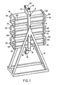
- the manifold apparatus of this invention includes one or a plurality of manifold segments 2, 4 and 6 connected together and which can be secured to manifold frame 8.
- Each end of the stack of manifold segments 2, 4 and 6 is provided with an optional litting block 10 or 12 to provide suitable inlets and outlets to the manifold apparatus such as is disclosed in U.S. Patent No. 5,147,542 which is incorporated herein by reference.
- suitable inlets and/or outlets can be positioned at a central location in the stack such as is disclosed in U.S. Patent 5,176,828 which is incorporated herein by reference.
- a fluid feed inlet 14 and a filtrate inlet 16 are provided on fitting block 12, each of which are in fluid communication with suitable fluid storage means (not shown).
- a plurality of filtration modules 22 are secured to manifold segments 2, 4 and 6 be means of a plate 19 and a plurality of compression assemblies 24 such as bolts.
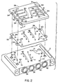
- the manifold apparatus of this invention includes a manifold segment 2, adaptor manifolds 26 and gaskets 28 which provide a sealing means for fluid flow paths within manifold segment 2 and adapter manifold 26.
- adaptor manifold 26 is rotated 180° toward the reader (arrow 17) to properly position it relative to manifold segment 2.
- Manifold segment 2 includes a retentate outlet conduit 36, a filtrate outlet conduit 38, a filtrate inlet conduit 40 and a fluid feed inlet conduit 42.
- Retentate outlet conduit 36 is in fluid communication with a plurality of retentate outlet means (holes) 44.
- Filtrate outlet conduit 38 is in fluid communication with filtrate outlet means (holes) 46.
- Filtrate inlet conduit 40 is in fluid communication with filtrate inlet means (holes) 48.
- Fluid feed inlet conduit 42 is in fluid communication with fluid feed inlet means (holes) 50. Holes 52 and 53 as well as slots 54 are provided for bolts 24.
- Fluid feed inlet means 50 are in fluid communication with holes 51 which extend through the thickness of adaptor manifold 26.
- Filtrate inlet means 48 are in fluid communication with slots 56, each of which have holes 58 extending through the remaining thickness of adaptor manifold 26.
- Retentate outlet means 44 are in fluid communication with holes 64 which extend through the thickness of adaptor manifold 26.
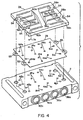
- adaptor manifold 26a is rotated 180° toward the reader (arrow 17a) to properly position it relative to manifold segment 2.
- Manifold segment 2 Includes a retentate outlet conduit 36a, a filtrate outlet conduit 38a, a filtrate inlet conduit 40a and a fluid feed inlet conduit 42a.
- Retentate outlet conduit 36a is in fluid communication with a plurality of retentate outlet means (holes) 44a.
- Filtrate outlet conduit 38a is in fluid communication with filtrate outlet means (holes) 46a.
- Filtrate inlet conduit 40a is in fluid communication with filtrate inlet means (holes) 48a.
- Fluid feed inlet conduit 42a is in fluid communication with fluid feed inlet means (holes) 50a. Holes 52 and 53 as well as slots 54 are provided for bolts 24.
- Retentate outlet means 44a are in fluid communication with slots 56a, each of which has a hole 58a which extends through the remaining thickness of adaptor manifold 26a.
- Filtrate inlet means 48a are in fluid communication with holes 64a, extending through the thickness of adaptor manifold 26a.
- Filtrate outlet means 46a are in fluid communication with holes 51a extending through the thickness of adaptor manifold 26a.
- Feed inlet means 50a are in fluid communication with slots 60a, each of which has a hole 62a extending through the remaining thickness of adaptor manifold 26a.
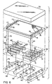
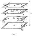
- a filtration module 70 useful with the manifold segment of this invention is described. Gaskets (not shown) are provided between elements to effect sealing in a manner well known in the art.
- the filtration module 70 is positioned between the adaptor manifold 26 and end plate 72.
- the filtration module 70 includes holes 74 which communicate with fluid feed inlet means 50 through path 71 and holes 76 which communicate with filtrate inlet means 48 to provide inlet filtrate stream 49.
- the filtrate inlet holes 76 provide filtrate on the filtrate side of a filter layer (see Fig. 5) to increase pressure there and to decrease pressure drop across the filter layer.
- Filtrate outlet holes 76 provide filtrate on the filtrate side of a filter layer (see Fig. 5) to increase pressure there and to decrease pressure drop across the filter layer.
- Filtrate outlet holes 78 communicate with filtrate outlet means 46 and filtrate outlet conduit 38 through path 73.
- the filtration segment 70 is also provided with holes 77 which communicate with retentate outlet means 44 through path 75.
- the plate 72 serves as a seal for the top surface of filtration module 70.
- the filtration module 70 includes a filtrate spacer 80, a filter layer 82, a retentate spacer 86 and a filter layer 84 with a second filtrate spacer 80 (not shown).
- the liquid feed represented by arrow 71 passes through filter 82 as represented by arrow 89.
- the remaining portion of the incoming liquid passes upwardly as represented by arrow 90 through holes 74 in filter 82, holes 74 in filtrate spacer 80 and into the next adjacent filtration module (not shown) wherein it proceeds as described above with reference to filtration module 70.
- the filtrate passes in the direction of arrows 81 into holes 78 and passes in a direction as shown by arrows 92 and 73 toward filtrate outlet conduit 38 (Fig.6).
- the retentate passes across retentate spacer 86 as shown by arrows 87 and 95 through holes 77 and to retentate outlet conduit 36 (Fig. 6) in a direction as shown by arrow 96.
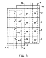
- Figs. 8-10 show representative flow arrangements for a stack of manifold segments and associated adaptor manifolds of this invention.
- a fluid feed inlet 14 introduces feed in parallel flow though manifold segments 2, 4, 6 and 7 through fluid feed conduits 42.
- Filtrate inlet 16 introduces filtrate also in parallel flow through manifold segment 2, 4, 6 and 7 through filtrate inlet conduits 40.
- Filtrate is removed from the stack by filtrate outlet 20 through filtrate outlet conduits 38.
- Retentate is removed from the stack by retentate outlet 18 through retentate outlet conduits 36.
- fluid feed inlet 14 introduces feed to a stack of manifold segments 3, 5, 9 and 11 through a centrally located manifold 13. Feed passes in series sequentially through fluid feed conduits 42a, 42b, 42c and 42d and out retentate outlet 18a as well as through fluid feed conduits 42f, 42g, 42h and 42e and out retentate outlet 18b. Filtrate is introduced through filtrate inlet 16 and in series through filtrate inlet conduits 40a and filtrate outlet conduit 38a and out filtrate outlet 20a. Filtrate also passes sequentially through filtrate inlet conduit 40c and filtrate outlet conduit 38c and out filtrate outlet 20b.
- fluid feed is introduced to a stack of manifold segments 15, 17, 21 and 23 through feed inlet 14 in centrally positioned manifold 25. Fluid feed passes through feed inlet conduits 42a and 42b to conduit 42c and out retentate outlets 18a and 18b. Filtrate is introduced through filtrate inlet 16 through filtrate inlet conduits 40a and 40b and into filtrate outlet conduits 38b and out filtrate outlets 20c and 20d.
- Feed fluid 31 is introduced in storage tank 33 and is pumped by pump 35 through feed inlet 14 into a stack of manifold segments, where It is separated into which is removed or recycled to tank 33 through retentate outlet 18.
- Filtrate is removed from stack 1 through filtrate outlet 20 and a portion of the filtrate is directed to storage tank 39 through conduit 41.
- a portion 43 of the filtrate is separated and stored.
- the remaining portion of the filtrate is pumped by pump 45 and introduced into stack 1 through filtrate inlet 16.
Landscapes
- Chemical & Material Sciences (AREA)
- Chemical Kinetics & Catalysis (AREA)
- Separation Using Semi-Permeable Membranes (AREA)
Description
Claims (10)
- A manifold apparatus for fluid filtration which comprises:characterized in thata manifold segment (2) having a first surface, a second surface, a third surface and a fourth surface,said third surface and said fourth surface being spaced apart from each other and being positioned between said first surface and said second surface,at least one of said third surface or said fourth surface having a plurality of fluid feed inlet means (50), a plurality of filtrate outlet means (46) and a plurality of retentate outlet means (44),said fluid feed inlet means (50) being in fluid communication with a fluid feed inlet conduit (42) positioned within said manifold segment (2),said filtrate outlet means (46) being in fluid communication with a filtrate outlet conduit (38) positioned within said manifold segment (2),said retentate outlet means (44) being in fluid communication with a retentate outlet conduit (36) positioned within said manifold segment (2),said fluid feed inlet conduit (42) being in fluid communication with a fluid feed inlet (14) on at least one of said first surface or said second surface,said filtrate outlet conduit (38) being in fluid communication with a filtrate outlet (20) on at least one of said first surface or said second surface,said retentate outlet conduit (36) being in fluid communication with a retentate outlet (18) on at least one of said first surface or said second surface,
said at least one of said third surface or said fourth surface of said manifold segment (2) has a plurality of filtrate inlet means (48),
said filtrate inlet means (48) being in fluid communication with a filtrate inlet conduit (40) positioned within said manifold segment (2),
said filtrate inlet conduit (40) being in fluid communication with a filtrate inlet (16) on at least one of said first surface or said second surface, and
said manifold apparatus comprises at least one adaptor manifold (26) having a fifth surface and a sixth surface opposite to the fifth surface through the thickness of the adaptor manifold (26), said adaptor manifold (26) being positioned with the fifth surface facing the third or fourth surface of said manifold segment (2), said adaptor manifold (26) having a first (51) and a second plurality of holes (58) extending through the thickness of the adaptor manifold (26) at a first peripheral section of the adaptor manifold from the fifth to the sixth surface, a third (64) and fourth plurality of holes (62) extending through the thickness of the adaptor manifold (26) at a second peripheral section of the adaptor manifold (26) opposite to the first peripheral section from the fifth to the sixth surface, a first (56) and second plurality of slots (60) extending at the fifth surface from a first internal section to the second plurality of holes (58) at the first peripheral section and from a second intrnal section to the fourth plurality of holes (62) at the second peripheral section, respectively, such that fluid communication is allowed through the adaptor manifold (26) from the fifth surface to the sixth surface via the first plurality of holes (51) from the plurality of feed inlet means (50), via the third plurality of holes (64) from the retentate outlet means (44), via the second plurality of holes (58) and the first plurality of slots (56) from the filtrate inlet means (40), and via the fourth plurality of holes (62) and the second plurality of slots (60) from the filtrate outlet means (46). - The apparatus of claim 1 wherein both said third surface and said fourth surface of said manifold segment (2) have a plurality of said fluid feed inlet means (50), a plurality of said filtrate inlet means (48), a plurality of said filtrate outlet means (46) and a plurality of said retentate outlet means (44), and
two of said adaptor manifolds (26) are provided wherein one of said adaptor manifolds (26) is positioned on said third surface of said manifold segment (2) and the other of said adaptor manifolds (26) is positioned on said fourth surface of said manifold segment (2). - The apparatus of claim 1 wherein a plurality of said manifold segments (2,4,6,7;3,5,9,11;15,17,21,23) are connected together to effect fluid communication between at least one of said filtrate inlet conduits (40) and said filtrate outlet conduits (38) in adjacent manifold segments and at least one of said fluid feed inlet conduits (42) and said retentate outlet conduits (36) in adjacent manifold segments.
- The apparatus of claim 3 wherein said plurality of manifold segments (3,5,9,11;15,17,21,23) have a first end and a second end and the first fluid feed inlet (14) is positioned between said first end and said second end and is in fluid communication with the fluid feed inlet conduits (42a,b,c,d,e,f,g,h;42a,b,c) positioned within said manifold segments (3,5,9,11;15,17,21,23)
- The apparatus of claim 4 wherein in said plurality of manifold segments a first retentate outlet (18) is positioned between said first end and said second end and being in fluid communication with retentate outlet conduits (36) within said manifold segments.
- The apparatus of claim 5 wherein in said plurality of manifold segments a first filtrate outlet (20) is positioned between said first end and said second end and being in fluid communication with filtrate outlet conduits (38) positioned within said manifold segments.
- The apparatus of claim 3 wherein said plurality of manifold segments (2,4,6,7) have a first end and a second end and the first fluid feed inlet (14) is positioned on said first end and is in fluid communication with the fluid feed inlet conduits (42) positioned within said manifold segments (2,4,6,7)
- The apparatus of claim 7 wherein in said plurality of manifold segments (2,4,6,7) a first retentate outlet (18) is positioned on said second end and is in fluid communication with retentate outlet conduits (36) within said manifold segments (2,4,6,7).
- The apparatus of claim 8 wherein a first filtrate outlet (20) is positioned on said first end, a second filtrate outlet (20) is positioned on said second end, said first filtrate outlet (20) and said second filtrate outlet (20) being in fluid communication with filtrate outlet conduits (38) positioned within said manifold segments
- An apparatus for filtering a feed fluid to produce a filtrate and a retentate which comprises the manifold apparatus of any one of claims 3 to 9, wherein a separate filtration module (70) is provided in fluid communication with each of said manifold segments and said adaptor manifold (26) is provided on each manifold segment to introduce feed fluid on a feed side of a filter layer in said filtration module (70) and to introduce filtrate on a filtrate side of said filter layer.
Applications Claiming Priority (3)
| Application Number | Priority Date | Filing Date | Title |
|---|---|---|---|
| US08/468,177 US5599447A (en) | 1995-06-06 | 1995-06-06 | Manifold apparatus for tangential flow filtration apparatus |
| US468177 | 1995-06-06 | ||
| PCT/US1996/010193 WO1996039245A1 (en) | 1995-06-06 | 1996-06-04 | Manifold apparatus for tangential flow filtration apparatus |
Publications (2)
| Publication Number | Publication Date |
|---|---|
| EP0873175A1 EP0873175A1 (en) | 1998-10-28 |
| EP0873175B1 true EP0873175B1 (en) | 2002-09-25 |
Family
ID=23858723
Family Applications (1)
| Application Number | Title | Priority Date | Filing Date |
|---|---|---|---|
| EP96921571A Expired - Lifetime EP0873175B1 (en) | 1995-06-06 | 1996-06-04 | Manifold apparatus for tangential flow filtration apparatus |
Country Status (4)
| Country | Link |
|---|---|
| US (1) | US5599447A (en) |
| EP (1) | EP0873175B1 (en) |
| DE (1) | DE69623994T2 (en) |
| WO (1) | WO1996039245A1 (en) |
Families Citing this family (46)
| Publication number | Priority date | Publication date | Assignee | Title |
|---|---|---|---|---|
| DE19850707C1 (en) * | 1998-11-04 | 2000-05-18 | Sartorius Gmbh | Distribution plate for crossflow cassette filtration devices |
| DE19910974A1 (en) * | 1998-12-28 | 2000-06-29 | Ulrich Weise | Filter bag having one or several reducing filter insert captures filter waste on several comb-like recesses on the length side of the base plate |
| US7108791B2 (en) * | 1999-09-14 | 2006-09-19 | Millipore Corporation | High-resolution virus removal methodology and filtration capsule useful therefor |
| US7186331B2 (en) * | 2001-03-06 | 2007-03-06 | Sasol Technology (Pty) Limited | Monitoring unit for monitoring the condition of a semi-permeable membrane |
| US6506300B2 (en) * | 2001-05-15 | 2003-01-14 | Sartorius Ag | Distributor plate for crossflow cassette-type filtration appliances |
| DE20120838U1 (en) * | 2001-12-27 | 2002-03-28 | QUATTROFLOW Fluid Systems GmbH, 37181 Hardegsen | filtration device |
| WO2003080226A1 (en) | 2002-03-19 | 2003-10-02 | Protonex Technology Corporation | Cross-flow filtration cassettes and methods for fabrication of same |
| USRE49221E1 (en) | 2002-06-14 | 2022-09-27 | Parker Intangibles, Llc | Single-use manifolds for automated, aseptic handling of solutions in bioprocessing applications |
| US9283521B2 (en) | 2002-06-14 | 2016-03-15 | Parker-Hannifin Corporation | Single-use manifold and sensors for automated, aseptic transfer of solutions in bioprocessing applications |
| US6712963B2 (en) * | 2002-06-14 | 2004-03-30 | Scilog, Llc | Single-use manifold for automated, aseptic transfer of solutions in bioprocessing applications |
| US20040020866A1 (en) * | 2002-07-22 | 2004-02-05 | Xerox Corporation | Liquid dispersion filtration and delivery apparatus and method |
| US6852219B2 (en) * | 2002-07-22 | 2005-02-08 | John M. Hammond | Fluid separation and delivery apparatus and method |
| US7297269B2 (en) * | 2003-10-31 | 2007-11-20 | Protonex Technology Corporation | Cross-flow filtration cassettes and methods for fabrication of same |
| WO2005058449A2 (en) * | 2003-12-12 | 2005-06-30 | Connors John F Jr | Plastic encapsulated tangential flow filter device and methods for making same |
| US7410574B2 (en) * | 2004-03-03 | 2008-08-12 | Patent Innovations Llc | Magnetic particle filtration apparatus |
| US7306727B2 (en) * | 2004-09-21 | 2007-12-11 | Millipore Corporation | Disposable tangential flow filtration device holder |
| WO2007030747A2 (en) * | 2005-09-09 | 2007-03-15 | Tangenx Technology Corporation | Laminated cassette device and methods for making same |
| EP1973635B1 (en) * | 2005-12-20 | 2011-06-08 | Tangenx Technology Corporation | Filtration assembly and methods for making and using same |
| US8177974B2 (en) * | 2006-04-14 | 2012-05-15 | Emd Millipore Corporation | Disposable tangential flow filtration device holder |
| US7959805B2 (en) * | 2006-07-28 | 2011-06-14 | Millipore Corporation | Manifold adaptor plate for filtration apparatus |
| US20080135499A1 (en) * | 2006-12-11 | 2008-06-12 | Pall Corporation | Filtration assemblies and methods of maintaining compression of filtration units in filtration assemblies |
| ATE532575T1 (en) * | 2006-12-11 | 2011-11-15 | Pall Corp | FILTER ASSEMBLIES AND METHOD FOR INSTALLING FILTERING UNITS IN FILTER ASSEMBLIES |
| US7918999B2 (en) * | 2006-12-11 | 2011-04-05 | Pall Corporation | Filtration assemblies, filtration manifolds, filtration units, and methods of channeling permeate |
| EP1946824B1 (en) * | 2006-12-11 | 2012-06-06 | Pall Corporation | Filtration assemblies with common manifold and use therof |
| US20080257813A1 (en) * | 2007-03-26 | 2008-10-23 | Millipore Corporation | Cassette-style filtration apparatus |
| US8454822B2 (en) | 2009-05-29 | 2013-06-04 | Emd Millipore Corporation | Disposable tangential flow filtration liner with sensor mount |
| DE102009027980A1 (en) * | 2009-07-23 | 2011-02-03 | Tariq Kaddoura | Wastewater treatment plant and method for treating wastewater and a wastewater treatment system |
| US20110174711A1 (en) * | 2009-08-04 | 2011-07-21 | Millipore Corporation | Self Contained Disposable Tangential Flow Filtration Liner |
| FR2960162B1 (en) | 2010-05-19 | 2012-08-17 | Millipore Corp | FILTRATION DEVICE WITH GAME OF AT LEAST ONE FILTERING CASSETTE |
| FR2960160B1 (en) * | 2010-05-19 | 2012-08-17 | Millipore Corp | FLUID BOND BLOCK FOR FILTRATION DEVICE HAVING AT LEAST ONE FILTER CASSETTE |
| US8919385B2 (en) * | 2010-11-24 | 2014-12-30 | Pall Corporation | Manifold plates and fluid treatment arrangements including manifold plates |
| WO2013082273A1 (en) | 2011-11-30 | 2013-06-06 | Wellstat Diagnostics, Llc. | Filtration module |
| DE102012002540B4 (en) * | 2012-02-09 | 2018-07-19 | Sartorius Stedim Biotech Gmbh | Filter module and modular filter system |
| US9075042B2 (en) | 2012-05-15 | 2015-07-07 | Wellstat Diagnostics, Llc | Diagnostic systems and cartridges |
| US9625465B2 (en) | 2012-05-15 | 2017-04-18 | Defined Diagnostics, Llc | Clinical diagnostic systems |
| US9213043B2 (en) | 2012-05-15 | 2015-12-15 | Wellstat Diagnostics, Llc | Clinical diagnostic system including instrument and cartridge |
| WO2015195452A2 (en) | 2014-06-16 | 2015-12-23 | Emd Millipore Corporation | Single-pass filtration systems and processes |
| US10550148B2 (en) | 2014-06-16 | 2020-02-04 | Emd Millipore Corporation | Methods for increasing the capacity of flow-through processes |
| CN115463546A (en) | 2014-06-25 | 2022-12-13 | Emd 密理博公司 | Filter element, tangential flow filtration system, method of producing a feed screen |
| ES2935333T3 (en) | 2014-08-29 | 2023-03-06 | Emd Millipore Corp | Processes for filtering liquids using single pass tangential flow filtration systems and tangential flow filtration systems with recirculation of retentate |
| CN105745009B (en) * | 2014-08-29 | 2018-09-28 | Emd 密理博公司 | Single-pass tangential flow filtration systems and tangential flow filtration systems with recirculation of retentate |
| USD762811S1 (en) * | 2014-12-18 | 2016-08-02 | Emd Millipore Corporation | Diverter plate |
| USD761381S1 (en) | 2014-12-18 | 2016-07-12 | Emd Millipore Corporation | Retentate plate |
| CA3023486C (en) | 2016-06-09 | 2022-03-29 | Emd Millipore Corporation | Radial-path filter elements, systems and methods of using same |
| DE102018004890B4 (en) * | 2018-06-19 | 2023-03-16 | Sartorius Stedim Biotech Gmbh | Filter system for biopharmaceutical processes, manifold plate for a filter system and method of making a filter system |
| KR20210132921A (en) * | 2020-04-28 | 2021-11-05 | 주식회사 아모그린텍 | filter module for water-purifying device using gravity and water-purifying device including the same |
Citations (1)
| Publication number | Priority date | Publication date | Assignee | Title |
|---|---|---|---|---|
| US4105547A (en) * | 1974-12-23 | 1978-08-08 | Alfa-Laval Ab | Filtering process |
Family Cites Families (8)
| Publication number | Priority date | Publication date | Assignee | Title |
|---|---|---|---|---|
| GB2003053B (en) * | 1977-08-19 | 1982-07-14 | Kuraray Co | Plate type fluid treatment apparatus |
| US4212747A (en) * | 1978-01-12 | 1980-07-15 | Phillips Petroleum Company | Shear-thickening compositions |
| US4430218A (en) * | 1980-07-18 | 1984-02-07 | Sartorius Gmbh | Separating device for fluids, consisting of support plates and cut sections of a semi-permeable diaphragm |
| JPS5935631B2 (en) * | 1980-07-24 | 1984-08-29 | テルモ株式会社 | Body fluid “filtration” device |
| US4849102A (en) * | 1988-05-31 | 1989-07-18 | Filtron Technology Corporation | Bidirectional ultrafiltration apparatus |
| US5096582A (en) * | 1990-09-25 | 1992-03-17 | Millipore Corporation | Tangential flow filtration apparatus |
| US5147542A (en) * | 1991-02-04 | 1992-09-15 | Millipore Corporation | Manifold and manifold segment for tangential flow filtration apparatus |
| US5176828A (en) * | 1991-02-04 | 1993-01-05 | Millipore Corporation | Manifold segment stack with intermediate feed manifold |
-
1995
- 1995-06-06 US US08/468,177 patent/US5599447A/en not_active Expired - Lifetime
-
1996
- 1996-06-04 WO PCT/US1996/010193 patent/WO1996039245A1/en not_active Ceased
- 1996-06-04 DE DE69623994T patent/DE69623994T2/en not_active Expired - Lifetime
- 1996-06-04 EP EP96921571A patent/EP0873175B1/en not_active Expired - Lifetime
Patent Citations (1)
| Publication number | Priority date | Publication date | Assignee | Title |
|---|---|---|---|---|
| US4105547A (en) * | 1974-12-23 | 1978-08-08 | Alfa-Laval Ab | Filtering process |
Also Published As
| Publication number | Publication date |
|---|---|
| DE69623994T2 (en) | 2003-08-07 |
| EP0873175A1 (en) | 1998-10-28 |
| WO1996039245A1 (en) | 1996-12-12 |
| DE69623994D1 (en) | 2002-10-31 |
| US5599447A (en) | 1997-02-04 |
Similar Documents
| Publication | Publication Date | Title |
|---|---|---|
| US5599447A (en) | Manifold apparatus for tangential flow filtration apparatus | |
| US5096582A (en) | Tangential flow filtration apparatus | |
| EP0498211B1 (en) | Manifold and manifold segment for tangential flow filtration apparatus | |
| EP0535546B1 (en) | Manifold segment stack with intermediate feed manifold | |
| CN100435912C (en) | Disposable membrane module with low-dead volume | |
| US4988445A (en) | Spiral wound filtration system and method of utilizing same | |
| US4956085A (en) | Filter plate, filter plate element and filter comprising same | |
| EP0777521B1 (en) | Apparatus for processing fluid and method for producing separated fluid | |
| US4411785A (en) | Reverse osmosis hollow fiber filter element | |
| KR950008628B1 (en) | Ultrafiltration apparatus | |
| EP0904147B1 (en) | Membrane filtration apparatus | |
| TWM541890U (en) | A filtration system to produce a permeate from a feedstock | |
| EP3202484B1 (en) | Inline diafiltration with multi-channel pump | |
| JP2885826B2 (en) | Method and apparatus for preventing the formation of a filter coating layer or disassembling a filter coating layer when filtering liquid containing finely dispersed components by orthogonal operation | |
| US5258122A (en) | Cross-flow filter device with pressure-balancing feature | |
| CN1762556A (en) | Disposable tangential flow filtration device holder | |
| US7635426B2 (en) | Tangential filtration housing | |
| US5160433A (en) | Laboratory scale ultrafiltration apparatus | |
| US4997565A (en) | Laboratory scale ultrafiltration apparatus | |
| EP1359993B1 (en) | Hollow fiber membrane cassette | |
| EP0310385A2 (en) | Filter plate, filter plate element, and filter comprising same | |
| KR102552181B1 (en) | Water treatment apparatus for equally distributing influent flow | |
| JP3251070B2 (en) | Manifold segment stack with intermediate feed manifold | |
| SU1064970A1 (en) | Apparatus for filtering at pressure through semipenetrable membranes | |
| EP1946824B1 (en) | Filtration assemblies with common manifold and use therof |
Legal Events
| Date | Code | Title | Description |
|---|---|---|---|
| PUAI | Public reference made under article 153(3) epc to a published international application that has entered the european phase |
Free format text: ORIGINAL CODE: 0009012 |
|
| 17P | Request for examination filed |
Effective date: 19980316 |
|
| AK | Designated contracting states |
Kind code of ref document: A1 Designated state(s): BE CH DE FR GB IT LI |
|
| 17Q | First examination report despatched |
Effective date: 19991103 |
|
| GRAG | Despatch of communication of intention to grant |
Free format text: ORIGINAL CODE: EPIDOS AGRA |
|
| GRAG | Despatch of communication of intention to grant |
Free format text: ORIGINAL CODE: EPIDOS AGRA |
|
| GRAH | Despatch of communication of intention to grant a patent |
Free format text: ORIGINAL CODE: EPIDOS IGRA |
|
| RAP1 | Party data changed (applicant data changed or rights of an application transferred) |
Owner name: MILLIPORE CORPORATION |
|
| GRAH | Despatch of communication of intention to grant a patent |
Free format text: ORIGINAL CODE: EPIDOS IGRA |
|
| GRAA | (expected) grant |
Free format text: ORIGINAL CODE: 0009210 |
|
| AK | Designated contracting states |
Kind code of ref document: B1 Designated state(s): BE CH DE FR GB IT LI |
|
| REG | Reference to a national code |
Ref country code: GB Ref legal event code: FG4D |
|
| REG | Reference to a national code |
Ref country code: CH Ref legal event code: EP |
|
| REF | Corresponds to: |
Ref document number: 69623994 Country of ref document: DE Date of ref document: 20021031 |
|
| REG | Reference to a national code |
Ref country code: CH Ref legal event code: NV Representative=s name: E. BLUM & CO. PATENTANWAELTE |
|
| ET | Fr: translation filed | ||
| RAP2 | Party data changed (patent owner data changed or rights of a patent transferred) |
Owner name: MILLIPORE CORPORATION |
|
| PLBE | No opposition filed within time limit |
Free format text: ORIGINAL CODE: 0009261 |
|
| STAA | Information on the status of an ep patent application or granted ep patent |
Free format text: STATUS: NO OPPOSITION FILED WITHIN TIME LIMIT |
|
| 26N | No opposition filed |
Effective date: 20030626 |
|
| REG | Reference to a national code |
Ref country code: CH Ref legal event code: PFA Owner name: MILLIPORE CORPORATION Free format text: MILLIPORE CORPORATION#80 ASHBY ROAD#BEDFORD MASSACHUSETTS 01730 (US) -TRANSFER TO- MILLIPORE CORPORATION#80 ASHBY ROAD#BEDFORD MASSACHUSETTS 01730 (US) |
|
| REG | Reference to a national code |
Ref country code: CH Ref legal event code: PFA Owner name: EMD MILLIPORE CORPORATION Free format text: MILLIPORE CORPORATION#80 ASHBY ROAD#BEDFORD MASSACHUSETTS 01730 (US) -TRANSFER TO- EMD MILLIPORE CORPORATION#290 CONCORD ROAD#BILLERICA, MA 01821 (US) |
|
| REG | Reference to a national code |
Ref country code: FR Ref legal event code: CD Owner name: EMD MILLIPORE CORPORATION Effective date: 20120327 |
|
| REG | Reference to a national code |
Ref country code: DE Ref legal event code: R082 Ref document number: 69623994 Country of ref document: DE Representative=s name: HENKEL, BREUER & PARTNER, DE |
|
| REG | Reference to a national code |
Ref country code: DE Ref legal event code: R082 Ref document number: 69623994 Country of ref document: DE Representative=s name: PATENTANWAELTE HENKEL, BREUER & PARTNER, DE Effective date: 20120613 Ref country code: DE Ref legal event code: R081 Ref document number: 69623994 Country of ref document: DE Owner name: EMD MILLIPORE CORPORATION, BILLERICA, US Free format text: FORMER OWNER: MILLIPORE CORP., BEDFORD, MASS., US Effective date: 20120613 |
|
| REG | Reference to a national code |
Ref country code: FR Ref legal event code: PLFP Year of fee payment: 20 |
|
| PGFP | Annual fee paid to national office [announced via postgrant information from national office to epo] |
Ref country code: CH Payment date: 20150612 Year of fee payment: 20 Ref country code: DE Payment date: 20150527 Year of fee payment: 20 Ref country code: GB Payment date: 20150603 Year of fee payment: 20 |
|
| PGFP | Annual fee paid to national office [announced via postgrant information from national office to epo] |
Ref country code: BE Payment date: 20150612 Year of fee payment: 20 Ref country code: FR Payment date: 20150608 Year of fee payment: 20 |
|
| PGFP | Annual fee paid to national office [announced via postgrant information from national office to epo] |
Ref country code: IT Payment date: 20150625 Year of fee payment: 20 |
|
| REG | Reference to a national code |
Ref country code: DE Ref legal event code: R071 Ref document number: 69623994 Country of ref document: DE |
|
| REG | Reference to a national code |
Ref country code: CH Ref legal event code: PL |
|
| REG | Reference to a national code |
Ref country code: GB Ref legal event code: PE20 Expiry date: 20160603 |
|
| PG25 | Lapsed in a contracting state [announced via postgrant information from national office to epo] |
Ref country code: GB Free format text: LAPSE BECAUSE OF EXPIRATION OF PROTECTION Effective date: 20160603 |