EP0872732B1 - Method and apparatus to compensate for gas chromatograph column permeability - Google Patents
Method and apparatus to compensate for gas chromatograph column permeability Download PDFInfo
- Publication number
- EP0872732B1 EP0872732B1 EP98106822.4A EP98106822A EP0872732B1 EP 0872732 B1 EP0872732 B1 EP 0872732B1 EP 98106822 A EP98106822 A EP 98106822A EP 0872732 B1 EP0872732 B1 EP 0872732B1
- Authority
- EP
- European Patent Office
- Prior art keywords
- column
- programs
- carrier gas
- conditions
- temperature
- Prior art date
- Legal status (The legal status is an assumption and is not a legal conclusion. Google has not performed a legal analysis and makes no representation as to the accuracy of the status listed.)
- Expired - Lifetime
Links
- 238000000034 method Methods 0.000 title claims description 53
- 230000035699 permeability Effects 0.000 title claims description 12
- 239000012159 carrier gas Substances 0.000 claims description 69
- 230000014759 maintenance of location Effects 0.000 claims description 45
- 239000007789 gas Substances 0.000 claims description 37
- 239000000470 constituent Substances 0.000 claims description 33
- 230000005526 G1 to G0 transition Effects 0.000 claims description 16
- 239000001307 helium Substances 0.000 claims description 12
- 229910052734 helium Inorganic materials 0.000 claims description 12
- SWQJXJOGLNCZEY-UHFFFAOYSA-N helium atom Chemical compound [He] SWQJXJOGLNCZEY-UHFFFAOYSA-N 0.000 claims description 12
- IJGRMHOSHXDMSA-UHFFFAOYSA-N Atomic nitrogen Chemical compound N#N IJGRMHOSHXDMSA-UHFFFAOYSA-N 0.000 claims description 8
- XKRFYHLGVUSROY-UHFFFAOYSA-N Argon Chemical compound [Ar] XKRFYHLGVUSROY-UHFFFAOYSA-N 0.000 claims description 6
- VNWKTOKETHGBQD-UHFFFAOYSA-N methane Chemical compound C VNWKTOKETHGBQD-UHFFFAOYSA-N 0.000 claims description 6
- 230000000694 effects Effects 0.000 claims description 5
- 239000012530 fluid Substances 0.000 claims description 5
- 238000012937 correction Methods 0.000 claims description 4
- 239000000203 mixture Substances 0.000 claims description 4
- 229910052757 nitrogen Inorganic materials 0.000 claims description 4
- 229910052786 argon Inorganic materials 0.000 claims description 3
- 239000001257 hydrogen Substances 0.000 claims description 3
- 229910052739 hydrogen Inorganic materials 0.000 claims description 3
- 125000004435 hydrogen atom Chemical class [H]* 0.000 claims description 3
- 238000013178 mathematical model Methods 0.000 claims 3
- 238000002347 injection Methods 0.000 claims 1
- 239000007924 injection Substances 0.000 claims 1
- 229910052705 radium Inorganic materials 0.000 claims 1
- HCWPIIXVSYCSAN-UHFFFAOYSA-N radium atom Chemical compound [Ra] HCWPIIXVSYCSAN-UHFFFAOYSA-N 0.000 claims 1
- 239000000463 material Substances 0.000 description 12
- VYPSYNLAJGMNEJ-UHFFFAOYSA-N Silicium dioxide Chemical compound O=[Si]=O VYPSYNLAJGMNEJ-UHFFFAOYSA-N 0.000 description 10
- 230000008859 change Effects 0.000 description 10
- 239000005350 fused silica glass Substances 0.000 description 10
- 238000000576 coating method Methods 0.000 description 5
- 239000011521 glass Substances 0.000 description 5
- 239000011248 coating agent Substances 0.000 description 4
- 238000004817 gas chromatography Methods 0.000 description 3
- 239000010410 layer Substances 0.000 description 3
- 239000000126 substance Substances 0.000 description 3
- XAGFODPZIPBFFR-UHFFFAOYSA-N aluminium Chemical compound [Al] XAGFODPZIPBFFR-UHFFFAOYSA-N 0.000 description 2
- 229910052782 aluminium Inorganic materials 0.000 description 2
- 238000013459 approach Methods 0.000 description 2
- 230000001276 controlling effect Effects 0.000 description 2
- 230000001419 dependent effect Effects 0.000 description 2
- 230000003993 interaction Effects 0.000 description 2
- 239000010935 stainless steel Substances 0.000 description 2
- 229910001220 stainless steel Inorganic materials 0.000 description 2
- 238000012360 testing method Methods 0.000 description 2
- 238000012546 transfer Methods 0.000 description 2
- ZAMOUSCENKQFHK-UHFFFAOYSA-N Chlorine atom Chemical compound [Cl] ZAMOUSCENKQFHK-UHFFFAOYSA-N 0.000 description 1
- 239000004642 Polyimide Substances 0.000 description 1
- NINIDFKCEFEMDL-UHFFFAOYSA-N Sulfur Chemical compound [S] NINIDFKCEFEMDL-UHFFFAOYSA-N 0.000 description 1
- 239000005864 Sulphur Substances 0.000 description 1
- 238000004458 analytical method Methods 0.000 description 1
- 230000003466 anti-cipated effect Effects 0.000 description 1
- QVGXLLKOCUKJST-UHFFFAOYSA-N atomic oxygen Chemical compound [O] QVGXLLKOCUKJST-UHFFFAOYSA-N 0.000 description 1
- 230000008901 benefit Effects 0.000 description 1
- 238000004364 calculation method Methods 0.000 description 1
- 238000012512 characterization method Methods 0.000 description 1
- 239000000460 chlorine Substances 0.000 description 1
- 229910052801 chlorine Inorganic materials 0.000 description 1
- 238000004587 chromatography analysis Methods 0.000 description 1
- 239000011247 coating layer Substances 0.000 description 1
- 239000002131 composite material Substances 0.000 description 1
- 238000005094 computer simulation Methods 0.000 description 1
- 238000010276 construction Methods 0.000 description 1
- 230000003247 decreasing effect Effects 0.000 description 1
- 238000001514 detection method Methods 0.000 description 1
- 230000005264 electron capture Effects 0.000 description 1
- 238000002474 experimental method Methods 0.000 description 1
- 238000013332 literature search Methods 0.000 description 1
- 238000007620 mathematical function Methods 0.000 description 1
- 238000005259 measurement Methods 0.000 description 1
- 238000012986 modification Methods 0.000 description 1
- 230000004048 modification Effects 0.000 description 1
- 239000001301 oxygen Substances 0.000 description 1
- 229910052760 oxygen Inorganic materials 0.000 description 1
- 230000000704 physical effect Effects 0.000 description 1
- 229920001721 polyimide Polymers 0.000 description 1
- 230000008569 process Effects 0.000 description 1
- 230000001105 regulatory effect Effects 0.000 description 1
- 230000004044 response Effects 0.000 description 1
- 238000000926 separation method Methods 0.000 description 1
Images
Classifications
-
- G—PHYSICS
- G01—MEASURING; TESTING
- G01N—INVESTIGATING OR ANALYSING MATERIALS BY DETERMINING THEIR CHEMICAL OR PHYSICAL PROPERTIES
- G01N30/00—Investigating or analysing materials by separation into components using adsorption, absorption or similar phenomena or using ion-exchange, e.g. chromatography or field flow fractionation
- G01N30/02—Column chromatography
- G01N30/86—Signal analysis
- G01N30/8693—Models, e.g. prediction of retention times, method development and validation
-
- G—PHYSICS
- G01—MEASURING; TESTING
- G01N—INVESTIGATING OR ANALYSING MATERIALS BY DETERMINING THEIR CHEMICAL OR PHYSICAL PROPERTIES
- G01N30/00—Investigating or analysing materials by separation into components using adsorption, absorption or similar phenomena or using ion-exchange, e.g. chromatography or field flow fractionation
- G01N30/02—Column chromatography
- G01N30/88—Integrated analysis systems specially adapted therefor, not covered by a single one of the groups G01N30/04 - G01N30/86
-
- G—PHYSICS
- G01—MEASURING; TESTING
- G01N—INVESTIGATING OR ANALYSING MATERIALS BY DETERMINING THEIR CHEMICAL OR PHYSICAL PROPERTIES
- G01N30/00—Investigating or analysing materials by separation into components using adsorption, absorption or similar phenomena or using ion-exchange, e.g. chromatography or field flow fractionation
- G01N30/02—Column chromatography
- G01N2030/022—Column chromatography characterised by the kind of separation mechanism
- G01N2030/025—Gas chromatography
-
- G—PHYSICS
- G01—MEASURING; TESTING
- G01N—INVESTIGATING OR ANALYSING MATERIALS BY DETERMINING THEIR CHEMICAL OR PHYSICAL PROPERTIES
- G01N30/00—Investigating or analysing materials by separation into components using adsorption, absorption or similar phenomena or using ion-exchange, e.g. chromatography or field flow fractionation
- G01N30/02—Column chromatography
- G01N30/88—Integrated analysis systems specially adapted therefor, not covered by a single one of the groups G01N30/04 - G01N30/86
- G01N2030/8804—Integrated analysis systems specially adapted therefor, not covered by a single one of the groups G01N30/04 - G01N30/86 automated systems
-
- G—PHYSICS
- G01—MEASURING; TESTING
- G01N—INVESTIGATING OR ANALYSING MATERIALS BY DETERMINING THEIR CHEMICAL OR PHYSICAL PROPERTIES
- G01N30/00—Investigating or analysing materials by separation into components using adsorption, absorption or similar phenomena or using ion-exchange, e.g. chromatography or field flow fractionation
- G01N30/02—Column chromatography
- G01N30/60—Construction of the column
- G01N30/6095—Micromachined or nanomachined, e.g. micro- or nanosize
-
- G—PHYSICS
- G01—MEASURING; TESTING
- G01N—INVESTIGATING OR ANALYSING MATERIALS BY DETERMINING THEIR CHEMICAL OR PHYSICAL PROPERTIES
- G01N30/00—Investigating or analysing materials by separation into components using adsorption, absorption or similar phenomena or using ion-exchange, e.g. chromatography or field flow fractionation
- G01N30/02—Column chromatography
- G01N30/86—Signal analysis
- G01N30/8658—Optimising operation parameters
Definitions
- a user of one gas chromatography system may want to utilize a method developed on another system and get retention times the same, or nearly the same, as those obtained on the other system for the same sample constituents. Even when the two gas chromatographs are very accurately calibrated, this has generally not been possible due to differences in column geometry from one column to another of the same type.
- F is the rate of flow through the material in cm 3 at standard temperature and pressure (STP)
- K is the permeation velocity in cm 3 gas (STP) mm thickness /s/cm 2 area/ cm Hg (gas pressure difference).
- P cmHg is the carrier gas pressure difference across the material in cm Hg
- a cm2 is the area of the exposed material in cm 2
- t mm is the thickness in mm.
- thermodynamic constants, a, b and c are then used to solve equation (7) 60 again as part of a model to predict retention times for other operating conditions 61 .
Landscapes
- Physics & Mathematics (AREA)
- Health & Medical Sciences (AREA)
- Life Sciences & Earth Sciences (AREA)
- Chemical & Material Sciences (AREA)
- Analytical Chemistry (AREA)
- Biochemistry (AREA)
- General Health & Medical Sciences (AREA)
- General Physics & Mathematics (AREA)
- Immunology (AREA)
- Pathology (AREA)
- Treatment Of Liquids With Adsorbents In General (AREA)
- Sampling And Sample Adjustment (AREA)
Description
- This invention relates to gas chromatographic instruments and particularly to the prediction of how retention times will change with variations in system operating conditions such as column temperature, carrier gas inlet and outlet pressure, carrier gas flow velocity and column dimensions.
- Gas chromatography involves physically separating constituents of a sample in a carrier gas, which flows through a column, and measuring the separated constituents. A pulse of the sample is injected into the flow of the carrier gas and the constituents interact with a stationary phase material in a column. At the end of the column the individual components are more or less separated in time. Detection of the carrier with the separated constituents provides a pattern of retention times, which, by calibration or comparison with known samples, indicates the constituents of the sample qualitatively and quantitatively. The main components of such a system are the column, an injector with a mixing chamber for introducing the sample into the carrier, a detector at the outlet end of the column, fluid controls, and a computer for treating and displaying the output of the detector. The display generally shows the height of each peak verses its retention time. An oven generally is used to elevate temperature to maintain the sample in a volatile state, and to improve the discrimination of constituents. A typical gas chromatographic system is disclosed in
U.S. patent No. 5,476,000 - It is often desirable to be able to predict how retention times will change in response to changes in the column temperature and inlet carrier gas pressure. Several cases of this are listed below:
- For example, a user of one gas chromatography system may want to utilize a method developed on another system and get retention times the same, or nearly the same, as those obtained on the other system for the same sample constituents. Even when the two gas chromatographs are very accurately calibrated, this has generally not been possible due to differences in column geometry from one column to another of the same type.
- Alternatively, a user may want to simulate effects of changes in temperature and pressure in order to optimize their values for achieving satisfactory separation between the retention times of the various possible sample constituents in the minimum analysis time. A means of achieving this is also described in the accompanying patent application. In addition to this invention, there are products on the market which also claim to be able to do this.
- Yet another reason for wanting to be able to make such predictions is to transfer a method from one column to another of a different geometry, possibly using a different carrier gas, and get the same retention time pattern. Means for achieving this are described, for example, in
U.S. patent 5,405,432 . - Other situations in which it is desirable to be able to predict the effect of changes in pressure on retention times involve changes in column outlet pressure, which is most commonly atmospheric pressure. One of these situations involves naturally occurring fluctuations in atmospheric pressure. Compensation for outlet pressure makes retention times more constant from one run to the next on a given system.
U. S. patent 5,476,000 describes a means for doing this. Another situation is the use of the same method on two different GC systems run at significantly different elevations. Compensation for the differences in atmospheric pressure must be made in order to get the same retention times on the two systems. - Another type of situation involving outlet pressure is the transfer of a method developed with one detector to systems using another detector operated at a different pressure. For example, a method may be developed using a mass spectrometer detector involving a near zero outlet pressure, and then used routinely on systems with atmospheric outlet pressure. In each of the above cases, it is desirable to be able to accurately calculate the change in operating conditions that will compensate for the change or difference in outlet pressure.
- The carrier gas holdup time is the time it takes a small segment of carrier gas to flow from one end of the column to the other. At constant temperature, the constituent retention times are proportional to the carrier gas holdup time. With temperature programming, there is a similar but more complex dependence on the holdup time. Because of this, all of the examples and situations listed above require the ability to accurately predict changes in carrier gas holdup times accompanying changes in column temperature and inlet pressure.
- According to the teachings of this invention there is disclosed herein a method for more accurately predicting retention times for various conditions in a gas chromatographic system utilizing the steps of: claim 1.
- There is further disclosed an apparatus comprising the features of
claim 38. - The accepted theory for making predictions of the retention time is based on the Poiseuille theory of flow of carrier gas. Through a combination of experimental measurements of carrier gas holdup times and computer simulations, we have deduced that the accepted theory is incomplete, especially in the very common case where the carrier gas is helium and the column is fabricated from fused silica. Correcting the theory is desirable for more accurate application in the examples and situations outlined above. Furthermore, it is important to be able to calculate the errors accompanying the use of the conventional theory.
- What the accepted theory does not take into account is the finite permeability of fused silica, or other column materials, to helium or other carrier gasses, and the variation of this permeability with temperature. By incorporating this phenomenon into the theory, we are able to make more accurate predictions of how the carrier gas holdup times, and thus the retention times of the simple constituents, vary with temperature and pressure. This increased accuracy improves the methods for reducing retention time variations and fluctuations outlined above.
- The retention times are related to the system characteristics and operating parameters by a mathematical function including thermodynamic constants associated with interactions of the constituents with the stationary phase of the column. The function relating retention times to those parameters such as temperature and pressure is based on theoretical relationships of a chromatographic system.
-
-
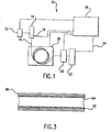
FIG. 1 is a schematic drawing of a chromatographic system incorporating the invention. -
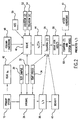
FIG. 2 is a flow chart of an embodiment of the method according to the invention. -
FIG. 3 is a longitudinal section of a portion of a chromatographic column as used in the system ofFIG. 1 . - The conventional expression for the gas holdup time, the time the carrier remains in the column, is written in different, but equivalent, algebraic forms by different authors. For an example, see G. Guiochon and C. L. Guillemin, " Quantitive Gas Chromatography" (Elsevier, New York, 1988), ). In
U. S. patent 5,405,432 the holdup time is not expressed directly; instead, it is related to other quantities such as the carrier gas velocity at the column outlet and the James-Martin correction factor for gas compressibilities. A convenient expression for the gas holdup time to at constant temperature is
- In this expression, η is the carrier gas viscosity at the column temperature, L is the column length, r is the inside radius of the column, pi is the column inlet pressure and po is the column outlet pressure.
- Equation (1) is readily derived from Poiseuille's law. It is convenient for our purposes to express this law in a different form given by P. C. Carmen in Flow of Gas Through Porous Media" (Butterworths, London, 1956), p. 62, equation (3.1) as

- Where x denotes position along the column, ux is the carrier gas velocity at x averaged across the column, and px is the pressure at x. In the standard theory it is assumed that the carrier is an ideal gas and that the carrier mass flow is the same at every point along the column. With these assumptions, the product ux px is a constant independent of x. In this case, equation (2) is readily solved for px and ux and equation (1) for the holdup time is obtained from

- Because of the importance of the gas holdup time in the examples and situations listed above, we have tested the above theory by measuring the helium gas holdup times over a wide range of column dimensions (radius and length), inlet pressure, and temperature. The holdup time was taken to be the retention time for an air sample measured with a thermal conductivity detector. The results were compared with those expected from equation (1) using viscosities for helium as a function of temperature provided by S. J. Hawkes, Chromatographia, 37, 399, 1993.
- The measured gas holdup times are expected to vary as the viscosity when the temperature is changed at constant inlet pressure. Deviation from this expected behavior is observed in fused silica columns with helium as the carrier gas. Under most practical combinations of column geometry and operating conditions the deviations are moderate: the gas holdup times typically increase ten percent less than expected. However, with long columns and low carrier gas velocities the deviations can be much greater. In this case, the holdup time increase significantly less rapidly than expected with increasing temperature at moderate temperatures Beyond a critical temperature, the helium flow from the outlet end of the column actually stops.
- When gas holdup times are measured as a function of inlet pressure at constant temperature, this phenomenon shows up as deviation from the pressure dependence of the Poiseuille law. As pressure is decreased from a high value, the gas holdup time first rises less rapidly than expected. Below a certain pressure, it rises more rapidly than expected.
- We have deduced that the deviations of our experimental results from the conventional theory are due to carrier gas permeating out through the column walls. A study of the literature shows that fused silica, the most common material for GC columns, has a high permeability to helium relative to that of other glasses. This is shown in data published by F. J. Norton, J. Am. Ceram. Soc. 36, 90, 1953. According to Norton the rate of carrier gas permeation through a layer of permeable material can be expressed as

- F is the rate of flow through the material in cm3 at standard temperature and pressure (STP), K is the permeation velocity in cm3 gas (STP) mm thickness /s/cm2 area/ cm Hg (gas pressure difference). PcmHg is the carrier gas pressure difference across the material in cm Hg, Acm2 is the area of the exposed material in cm2 and tmm is the thickness in mm. K is strongly temperature dependent. Its value as a function of temperature can be expressed as:

- It is convenient for our purposes to use the ideal gas law to express the loss of carrier gas in terms of a change in px ux, change the pressure units to Pascals, take into account the cylindrical geometry of the column, and express length in meters and radius in mm. Making these changes we obtain

- deux px) is the change in uxpx in units of a Pa m/s over a length of dx m. Ts is the normal temperature in K, P1 is the normal pressure in Pa, and ro is the outer radius of the column.
- In order to calculate ux, equations (4) and (5) must be solved simultaneously. These equations are readily integrated numerically using a modem laboratory or office PC. The ux values thus calculated are then entered into equation (3) to calculate the gas holdup time. In this case, equation (3) cannot be solved in closed form, but must be integrated numerically.
- For isothermal chromatography, the modified calculation of carrier gas holdup time is the only change required to calculate retention times. For temperature programming, the situation is not this simple. Retention time tR, for a given constituent of the sample is calculated from the integral equation:

where a, b and c are thermodynamic parameters for the constituent and its interaction with the stationary phase material. β, the phase ratio of the column, is equal to r/2 d, where d is the thickness of the stationary phase. The carrier gas velocity ux is a function of temperature, which is in turn a function of time when temperature programming. In solving equation (7), one must keep track of the position x of the constituent as a function of time. - In the conventional theory, the average carrier gas velocity along the column at temperature T, uavg = L/to, is substituted for ux in equation (7). The retention times are then calculated from equation (8):

- This is easier to solve than equation (7) because u does not depend on x and it is not necessary to keep track of the position of the constituent. Within the framework of the conventional theory this is valid because the pattern of the velocities along the column does not change with temperature. When permeation is taken into account, as described above, the pattern of the velocities does change with temperature. Because of this equation (7) must be used.
- The above does not consider the effects of the stationary phase or the column's polyimide outer coating on the permeation of carrier gas through the column. There are two possible approaches to these layers. One is to assume that their impedance to carrier permeation is negligible compared to the fused silica and thus ignore them. The other is to determine what they are, either through a literature search or experiment, and to include them if necessary.
- Another aspect involves the use of other column materials and coatings to minimize carrier gas permeability. We have experimental data on a very long stainless steel column that indicates that a small, but noticeable, amount of helium permeation is occurring. It is contemplated that an aluminum coating, which is sometimes placed on fused silica columns, would significantly impede carrier gas permeation.
- Norton (reference above) shows that many different glasses exhibit significantly less helium permeation than fused silica. It is part of this invention that other less permeable glasses be used to reduce or eliminate carrier gas permeation. One possibility is to fabricate composite columns with an inside surface of fused silica surrounded by a layer of less permeable glass. This would preserve the desirable inside surface properties of fused silica while significantly reducing carrier permeation.
- The above invention may be utilized in several ways in the examples and situations outlined in the Background of the Invention. The most straightforward is the use the theory directly as described. This involves using equations (2) and (6) to solve for the ux values as a function of both x and T, and to use these values to solve equation (7) for thermodynamic properties. These thermodynamic properties are then used to solve equation (7) again to determine standardized retention times for a desired set of conditions. This requires assuming that the nominal geometric parameters of the column, which is all that is generally known, are close enough to the actual for good accuracy. While imperfect, this will produce better accuracy than the conventional theory.
- There are also any number of approximate approaches which may be used. For example, with the procedures described above for correctly calculating holdup times, the holdup times for a wide range of situations can be simulated. The results can then be used to deduce a correction to equation (1) along with the range of its validity. This can be used in equation (7) to estimate retention times. While this procedure is only approximate, it has the advantage of requiring only minor modification to existing programs. The invention is utilized in a conventional gas chromatographic system such as described in the above mentioned
U.S. patent No. 5,476,000 . - In
Figure 1 , atypical GC system 10 is shown. A carrier gas from a pressure-regulatedsource 12 is supplied to aninjector device 14. A typical carrier gas in a GC system might be argon, helium, hydrogen, methane or nitrogen. A portion of the carrier is passed from theinjector 14 into and through achromatographic column 16. Apressure transducer 18 is connected to measure pressure at the inlet to the column. - A pulse of the sample is injected into the carrier in the injector device where a mixture is formed with the carrier gas. The sample used for characterization may contain organic molecules in combination with chlorine, oxygen, nitrogen or sulphur. The pulsed mixture passes through the column, typically taking several minutes. A stationary phase of a suitable substance on the inside column wall interacts with the chemical constituents of the sample. Different constituents have different affinities for the stationary phase and thereby exit the column at different characteristic retention times. The velocity of the carrier gas contributes to the total retention time.
- A
second pressure transducer 20 is connected to measure pressure at the outlet of the column. Adetector 22 at the column outlet measures a physical property of the carrier and mixture, the magnitude of the property changing with each constituent passing through. Various types of detectors are used, such as hot wire, flame ionization, electron capture, thermionic and flame photometric. The detector effects signals on aline 24, the signals being representative of the retention times. Thecolumn 16 is enclosed in anoven 26. - A
computer 28 regulates the pressure ofcarrier gas source 12, receives pressure information frominlet transducer 18, controls the temperature ofoven 26, receives pressure information fromoutlet transducer 20 and also receives and processes the signals online 28 into a series of peaks representative of the sample constituents, the plotted locations of the components representing corresponding retention times. The inlet pressure is controlled by controlling the pressure of the carrier gas source. The carrier gas source can be controlled by a pressure program which could maintain a constant pressure or cause the pressure to vary. The oven can be controlled by a temperature program which could include an isothermal method or one that varies the temperature by controlling starting and final temperatures, ramp rates and dwell times at each temperature. The column outlet pressure can also be controlled by a pressure program which could maintain a constant pressure or cause the pressure to vary. The carrier gas source, inlet pressure and outlet pressure can also be controlled by a carrier gas flow velocity program which can cause a constant or variable carrier gas flow velocity within the column. The computer displays the retention times directly or other indicators computed from the retention times. The components are then identified by an operator or the computer as known chemical constituents, with the peak heights providing a quantitative measure. -
Figure 2 illustrates one embodiment of the method of the invention.Primary system 10 is a typical gas chromatograph as shown inFigure 1 . The first step is to supply the system with atest sample 30 and enter operating parameters including aninlet pressure 32 andvarious temperature programs 34. The system then operates 36 and generatesretention times 38 which are then identified 40 for each constituent of the test sample under each temperature program.Outlet pressure 42 is also read. The next step is to calculate thecarrier gas velocities 44 at each of several different distances (x's) along the column at each of several temperatures over the anticipated range of system operating temperatures. We have determined experimentally that the number of positions x, may be a number greater than 200. The result is a two-dimensional array of values. Solving 46 for these velocities requires thecolumn dimensions 48, thepermeability 50 of the column material to the carrier gas as a function of pressure, theinlet pressure 32, theoutlet pressure 42, as well as equation (2) 52 and equation (6) 54. Thevelocities 44 along with thetemperature programs 34 and theretention time 38 for eachsample constituent 40 under each temperature program are entered into equation (7) 56. Equation (7) is solved for each of three different sets of data. The thermodynamic parameters, a, b and c are then calculated 58 for each sample constituent. The thermodynamic constants a and b are related to enthalpy and entropy and are temperature dependent. Thermodynamic constant c is introduced to compensate for this temperature dependency. All of a, b and c are deemed to be constant for each sample constituent but generally are different for different constituents and stationary phases. The thermodynamic constants, a, b and c are then used to solve equation (7) 60 again as part of a model to predict retention times forother operating conditions 61. -
Figure 3 shows the construction of a column. Atube 62 is constructed of fused silica or other suitable material. The appropriate stationary phase 64 is present on the tube's inside surface. Acoating 66 is present on the outside surface of the tube to impede permeation of the carrier gas through the tube. The coating layer is only as thick as required to obtain the desired permeation impedance to the carrier gas. Example coating materials are aluminum, glass or stainless steel.
Claims (48)
- A method of predicting retention time for analytes in a fluid sample, the fluid sample injected into a carrier gas in an injector device (14), wherein a portion of the carrier gas is passed from the injector device (14) into a gas chromatograph column (16) in a gas chromotograph system (10), said colund (16) having a stationary phase (64) therein and the carrier gas moving through said column (16) to contact said stationary phase (64), said method comprising the steps of:a) detecting said analytes under a number of sets of given operating conditions;b) calculating values for various parameters characteristic of the system. (10) based on a mathematical model;c) entering into said model said values for said characteristic parameters and at least one further set of conditions; andd) using said model to predict retention times for conditions,characterized in that said mathematical model includes a correction to compensate for the permeability of said column (16) to said carrier gas, wherein the permeability of said column (16) includes the carrier gas permeating out through the column walls, and that said using of said model to predict retention times of step d is used for operating conditions other than those of step a.
- The method of claim 1 wherein said sets of given conditions include themperature programs (34) as a function of time for said column (16).
- The method of claim 2 wherein said temperature programs (34) are isothermal.
- The method of claim 2 wherein said temperature programs (34) comprise starting and final temperatures, ramp rates and dwell times at each temperature.
- The method of claim 1 wherein said sets of given conditions include column inlet pressure programs.
- The method of claim 5 wherein said column inlet pressure programs maintain constant column inlet pressure (32).
- The method of claim 5 wherein said column inlet pressure programs cause column inlet pressure (32) to vary.
- The method of claim 1 wherein said sets of given conditions include carrier gas flow velocity programs.
- The method of claim 8 wherein said flow velocity programs maintain constant carrier gas flow velocity (44).
- The method of claim 8 wherein said flow velocity programs cause carrier gas flow velocity (44) to vary.
- The method of claim 1 wherein said sets of given conditions include column outlet pressure programs.
- The method of claim 11 wherein said column outlet pressure programs maintain constant column outlet pressure (42).
- The method of claim 11 wherein said column outlet pressure programs cause column outlet pressure (42) to vary.
- The method of claim 1 wherein said sets of given conditions include column dimensions (48).
- The method of claim 14 wherein said column dimensions (48) include column length, column diameter and thickness of said column stationary phase (64).
- The method of claim 1 wherein said various parameters characteristic of the system (10) include thermodynamic characteristics.
- The method of clainn 16 wherein said thermodynamic characteristics include factors for entropy and enthalpy of said carrier gas and a factor to account for changes in said entropy and enthalpy related to temperature.
- The method of claim 1 wherein said at least one further set of conditions includes temperature programs (34) for said column (16).
- The method of claim 18 wherein said temperature programs(34) are isothermal
- The method of claim 18 wherein said temperature programs (34) comprise starting and final temperatures, ramp rates and dwell times at each temperature.
- The method of claim 1 wherein said at least one further set of conditions include column inlet pressure programs.
- The method of claim 21 wherein said column inlet pressure programs maintrain constant column inlet pressure (32).
- The method of claim 21 wherein said column inlet pressure programs cause column inlet pressure (32) to vary.
- The method of claim 1 wherein said at least one further set of conditions include carrier gas flow velocity programs.
- The method of claim 24 wherein said flow velocity programs maintain constant carrier gas flow velocity(44).
- The method of claim 24 wherein said flow velocity programs cause carrier gas flow velocity (44) to vary.
- The method of claim 1 wherein said at least one further set of conditions include column outlet pressure programs.
- The method of claim (27) wherein said column outlet pressure programs maintain constant column outlet pressure (42).
- The method of claim 27 wherein said column outlet pressure programs cause column outlet pressure (42) to vary.
- The method of claim 1 wherein said at least one further set of conditions include column dimensions (48).
- The method of claim 30 wherein said column dimensions (48) include column length, column diameter and the thickness of said column stationary phase (64).
- The method of claim 1 wherein said carrier gas is a gas selected from the group consisting of argon, helium, hydrogen, methane and nitrogen.
- A method of claim 1, wherein said gas chromatograph system (10) includes a temperature programmable oven (26), the column(16) being positioned inside said oven (26) having an inlet and an outlet, means for passing carrier gas through said column (16), means for controlling the pressure at said inlet, means for measuring the pressure at said outlet, injection means for injecting a pulse of sample fluid having constituents into said carrier gas at said inlet to effect a fluid mixture passing through said column (16) subject to retention times for said constituents, detector means receptive of said constituents for effecting signals representative of peak heights verses retention times of said constituents and processing means receptive of said signals for presenting peak heights verses measured retention times, said method further comprising:specifying a plurality of temperature programs(34) for said oven(26);specifying an inlet pressure (32);injecting a sample having constituents during each temperature program;measuring measured retention times of said constituents for each temperature program (34);measuring an outlet pressure (42);determining dimensions (48) of said column (16) including a column length and a column radium;determining column permeability (50) to said carrier gas as a function of pressure;dividing length of said column (16) into a plurality of equal distances;selecting a plurality of temperatures from said temperature programs (34);determining viscosity of said carrier gas at each selected temperaturecalculating carrier gas velocity at points corresponding to each of said plurality of equal distances and at each of said plurality of temperatures as a function of said inlet pressure (32), said outlet pressure(42), said column dimensions 48 and said permeability (50);calculating thermodynamic parameters of each constituent as a function of said carrier gas velocities, said temperature programs (34), said retention times, said column dimensions (48) and said viscosities; andcalculating retention times as a function of said thermodynamic parameters.
- The method of claim 33 wherein said carrier gas is a gas selected from the group consisting of argon, helium, hydrogen, methane and nitrogen.
- The method of claim 33 wherein said plurality of equal distances is greater than 200.
- The method of claim 33 wherein said thermodynamic parameters are related to entropy and enthalpy of said constituents.
- The method of claim 33 wherein said column comprises a stationary phase (64) having an effective phase thickness and said column dimensions(48) comprise said phase thickness, column length, and column radius.
- A gas chromatograph system (10) having a column (16); a stationary phase (64) within said column (16) and a carrier gas for carrying a sample containing analytes past said stationary phase (64), the improvement comprising:a data handling system including a mathematical model, said model having:a) first inputs including retention times determined during a number of sets of conditions of operation of said system (10);
said data handling system having prediction means for inputting to said model a set of operating conditions other than those of a) and for inputting said set of parameters, and for predicting retention times for said operating conditions,characterized in that said model is used for predicting retention times at a variety of conditions of operation of the system (10) and said model having:and that said prediction means are predicting retention times for operating conditions other than those of a).b) a second input representative of a correction to compensate for the permeability of the column (16) to said carrier gas, wherein the permeability of said column (16) includes the carrier gas permeating out through the column walls - The gas chromatograph system of claim 38 wherein said numbers of sets of conditions of operation include temperature programs as a function of time for said column (16).
- The gas chromatograph system of claim 38 wherein said numbers of sets of conditions of operation include column inlet pressure programs.
- The gas chromatograph system of claim 38 wherein said numbers of sets of conditions of operation include carrier gas flow velocity programs.
- The gas chromatograph system of claim 38 wherein said numbers of sets of conditions of operation include column outlet pressure programs.
- The gas chromatograph system of claim 38 wherein said numbers of sets of conditions of operation include column dimensions (48).
- The gas chromatograph system of claim 38 wherein said conditions other than those of a) includes temperature programs (34) for said column (16).
- The gas chromatograph system of claim 38 wherein said conditions other than those of a) include column inlet pressure programs.
- The gas chromatograph system of claim 38 wherein said conditions other than those of a) include carrier gas flow velocity programs.
- The gas chromatograph system of claim 38 wherein said conditions other than those of a) include column outlet pressure programs.
- The gas chromatograph system of claim 38 wherein said conditions other than those of a) include column dimensions (48).
Applications Claiming Priority (2)
| Application Number | Priority Date | Filing Date | Title |
|---|---|---|---|
| US4355097P | 1997-04-15 | 1997-04-15 | |
| US43550P | 1997-04-15 |
Publications (2)
| Publication Number | Publication Date |
|---|---|
| EP0872732A1 EP0872732A1 (en) | 1998-10-21 |
| EP0872732B1 true EP0872732B1 (en) | 2014-02-12 |
Family
ID=21927733
Family Applications (1)
| Application Number | Title | Priority Date | Filing Date |
|---|---|---|---|
| EP98106822.4A Expired - Lifetime EP0872732B1 (en) | 1997-04-15 | 1998-04-15 | Method and apparatus to compensate for gas chromatograph column permeability |
Country Status (3)
| Country | Link |
|---|---|
| US (1) | US5915269A (en) |
| EP (1) | EP0872732B1 (en) |
| JP (1) | JP4343284B2 (en) |
Families Citing this family (16)
| Publication number | Priority date | Publication date | Assignee | Title |
|---|---|---|---|---|
| NL1008381C2 (en) * | 1998-02-20 | 1999-08-24 | X Flow Bv | Filter device. |
| EP1285265A1 (en) * | 2000-05-23 | 2003-02-26 | Discovery Partners International, Inc. | High-throughput purification process |
| US6558626B1 (en) * | 2000-10-17 | 2003-05-06 | Nomadics, Inc. | Vapor sensing instrument for ultra trace chemical detection |
| ITMI20022605A1 (en) * | 2002-12-09 | 2004-06-10 | Thermo Finnigan Italia S P A | METHOD AND EQUIPMENT TO KEEP RETENTION TIMES CONSTANT IN GAS CHROMATOGRAPHIC ANALYSIS. |
| JP5002530B2 (en) * | 2008-05-23 | 2012-08-15 | 株式会社日立ハイテクノロジーズ | Method for converting measurement method of liquid chromatograph and liquid chromatograph apparatus |
| US8141411B2 (en) * | 2008-09-30 | 2012-03-27 | Thermo Finnigan Llc | Method for determining a low cylinder pressure condition for a gas chromatograph |
| CN102507812B (en) * | 2011-09-26 | 2014-01-15 | 天津大学 | A Prediction Method of Retention Time in Double-column Tandem Gas Chromatography |
| EP2581741B1 (en) * | 2011-10-12 | 2019-09-18 | Agilent Technologies, Inc. | Method transfer by freezing an initially non-controlled parameter |
| CN103076419B (en) * | 2012-12-27 | 2014-10-15 | 天津大学 | Method for forecasting temperature programmed gas chromatograph retention time |
| JP2014206510A (en) * | 2013-04-15 | 2014-10-30 | 株式会社堀場エステック | Gas chromatograph data processor, data processing method and data processing program |
| KR101955288B1 (en) * | 2015-10-06 | 2019-03-08 | 주식회사 엘지화학 | A device for high speed analyzing of gas sample using gas-chromatograph and a method thereof |
| JP6642271B2 (en) * | 2016-05-24 | 2020-02-05 | 株式会社島津製作所 | Gas chromatograph |
| US11009489B2 (en) | 2016-06-29 | 2021-05-18 | Agilent Technologies, Inc. | Method and system for reducing the effects of column bleed carryover |
| US10794875B2 (en) | 2018-11-26 | 2020-10-06 | Shimadzu Corporation | Gas chromatograph |
| GB2636487B (en) * | 2020-11-17 | 2025-09-24 | Agilent Technologies Inc | Gas Chromatography Systems and Methods with Diagnostic and Predictive Module |
| CN112858376B (en) * | 2021-01-04 | 2023-12-29 | 广西防城港核电有限公司 | Method for determination of dissolved hydrogen content in reactor primary circuit |
Family Cites Families (20)
| Publication number | Priority date | Publication date | Assignee | Title |
|---|---|---|---|---|
| GB1090438A (en) * | 1965-01-05 | 1967-11-08 | Technicon Instr | Indicating the quantities of the constituents of a sample from chromatographic curves |
| US3500028A (en) * | 1965-03-10 | 1970-03-10 | Foster Grant Co Inc | Automatic chromatography system |
| US3585002A (en) * | 1965-10-22 | 1971-06-15 | Sinclair Research Inc | Fluid analysis by gas chromatography employing multiple carrier gases and multiple columns |
| US3501700A (en) * | 1967-08-17 | 1970-03-17 | Universal Oil Prod Co | Chromatograph output system suitable for use with process control |
| US3722181A (en) * | 1970-05-22 | 1973-03-27 | Du Pont | Chromatographic packing with chemically bonded organic stationary phases |
| US3733474A (en) * | 1971-09-01 | 1973-05-15 | Texaco Inc | Apparatus and method for providing corrected normalized signals corresponding to the composition of a material |
| DE2245815A1 (en) * | 1972-09-19 | 1974-03-28 | Bodenseewerk Perkin Elmer Co | METHOD AND DEVICE FOR IDENTIFYING AND EVALUATING PEAKS IN CHROMATOGRAMS |
| US4054432A (en) * | 1976-06-11 | 1977-10-18 | Wright State University | Polymer lined capillary column and method for producing same |
| JPH0718853B2 (en) * | 1984-05-15 | 1995-03-06 | 住友化学工業株式会社 | Data processing method in chromatography |
| US4835708A (en) * | 1987-07-06 | 1989-05-30 | Spectra Physics, Inc. | Method and apparatus for analysis of chromatograms using cross-correlation and moment analysis |
| US4824446A (en) * | 1988-05-23 | 1989-04-25 | Applied Automation, Inc. | Gas chromatography simulation |
| US5121443A (en) * | 1989-04-25 | 1992-06-09 | Spectra-Physics, Inc. | Neural net system for analyzing chromatographic peaks |
| US5163979A (en) * | 1991-06-27 | 1992-11-17 | The Dow Chemical Company | Pressure programmable gas chromatograph regulator |
| JPH08500898A (en) * | 1992-04-16 | 1996-01-30 | ザ ダウ ケミカル カンパニー | An improved method for interpreting complex data to detect abnormal equipment or processing behavior |
| DE69323645T2 (en) * | 1992-05-18 | 1999-09-09 | Hewlett-Packard Co. | Procedure for calculating the operating parameters of a gas chromatograph |
| JP2957802B2 (en) * | 1992-05-19 | 1999-10-06 | 株式会社日立製作所 | Chromatographic equipment |
| US5476000A (en) * | 1994-03-31 | 1995-12-19 | Hewlett-Packard Company | Retention time stability in a gas chromatographic apparatus |
| US5545252A (en) * | 1995-03-01 | 1996-08-13 | The Perkin-Elmer Corporation | Flow regulation in gas chromatograph |
| US5719322A (en) * | 1996-09-20 | 1998-02-17 | Uop | Zeolitic capillary columns for gas chromatography |
| US5827946A (en) * | 1997-04-30 | 1998-10-27 | Hewlett-Packard Company | Method for sample identification using a locked retention time database |
-
1998
- 1998-04-14 US US09/059,927 patent/US5915269A/en not_active Expired - Lifetime
- 1998-04-15 JP JP10512298A patent/JP4343284B2/en not_active Expired - Lifetime
- 1998-04-15 EP EP98106822.4A patent/EP0872732B1/en not_active Expired - Lifetime
Also Published As
| Publication number | Publication date |
|---|---|
| EP0872732A1 (en) | 1998-10-21 |
| US5915269A (en) | 1999-06-22 |
| JPH10325835A (en) | 1998-12-08 |
| JP4343284B2 (en) | 2009-10-14 |
Similar Documents
| Publication | Publication Date | Title |
|---|---|---|
| US5915269A (en) | Method and apparatus to compensate for gas chromatograph column permeability | |
| JP4691603B2 (en) | Method for measuring the value of one or more specific parameters of a chromatographic system | |
| Ettre et al. | Determination of gas-liquid partition coefficients by automatic equilibrium headspace-gas chromatography utilizing the phase ratio variation method | |
| EP0396884B1 (en) | Gas chromatograph having integrated pressure programmer | |
| US5361625A (en) | Method and device for the measurement of barrier properties of films against gases | |
| Fowlis et al. | A vapour dilution system for detector calibration | |
| CA1319030C (en) | Control arrangement for the chromatography of liquids | |
| Oberholtzer et al. | Precise gas-chromatographic measurements | |
| JPH07280786A (en) | Chromatographic analysis method of fluid | |
| GB2297045A (en) | Sensor drift correction in a gas chromatograph | |
| EP0840116B1 (en) | Calibration method for a chromatography column | |
| US5265463A (en) | Apparatus for measuring the transmission rate of volatile organic chemicals through a barrier material | |
| RU2125262C1 (en) | Method determining calorific power of combustible gas and device for its realization | |
| Kreisberg et al. | Development of an automated high-temperature valveless injection system for online gas chromatography | |
| Gruber et al. | The determination of activity coefficients at infinite dilution with the help of the dilutor technique (inert gas stripping) | |
| WO2004083848A1 (en) | Gas chromatograph with fast btu analysis | |
| US4838098A (en) | Contained radiological analytical chemistry module | |
| US20260092904A1 (en) | Gas chromatograph with dynamic response factors | |
| Kreisberg et al. | Development of an automated high temperature valveless injection system for on-line gas chromatography | |
| SU1045083A1 (en) | Polymer membrane permeability determination method | |
| SU787984A1 (en) | Chromodistillation method of mixture analysis | |
| Raal et al. | Gas chromatograph calibration of gas mixtures using a versatile precision volumetric apparatus | |
| RU199841U1 (en) | GAS CHROMATOGRAPH | |
| US20060123987A1 (en) | Method and apparatus for keeping constant the retention times in a gaschromatographic analysis | |
| Williams et al. | Computer spreadsheet calculation of the optimum temperature and column lengths for serially coupled capillary gas chromatographic columns |
Legal Events
| Date | Code | Title | Description |
|---|---|---|---|
| PUAI | Public reference made under article 153(3) epc to a published international application that has entered the european phase |
Free format text: ORIGINAL CODE: 0009012 |
|
| AK | Designated contracting states |
Kind code of ref document: A1 Designated state(s): CH DE FR GB IT LI NL |
|
| AX | Request for extension of the european patent |
Free format text: AL;LT;LV;MK;RO;SI |
|
| 17P | Request for examination filed |
Effective date: 19990416 |
|
| AKX | Designation fees paid |
Free format text: CH DE FR GB IT LI NL |
|
| RAP1 | Party data changed (applicant data changed or rights of an application transferred) |
Owner name: PERKINELMER LAS, INC. |
|
| RAP1 | Party data changed (applicant data changed or rights of an application transferred) |
Owner name: PERKINELMER LAS, INC. |
|
| R17C | First examination report despatched (corrected) |
Effective date: 20070420 |
|
| GRAP | Despatch of communication of intention to grant a patent |
Free format text: ORIGINAL CODE: EPIDOSNIGR1 |
|
| INTG | Intention to grant announced |
Effective date: 20130830 |
|
| RAP1 | Party data changed (applicant data changed or rights of an application transferred) |
Owner name: PERKINELMER HEALTH SCIENCES, INC. |
|
| GRAS | Grant fee paid |
Free format text: ORIGINAL CODE: EPIDOSNIGR3 |
|
| GRAA | (expected) grant |
Free format text: ORIGINAL CODE: 0009210 |
|
| AK | Designated contracting states |
Kind code of ref document: B1 Designated state(s): CH DE FR GB IT LI NL |
|
| REG | Reference to a national code |
Ref country code: GB Ref legal event code: FG4D |
|
| REG | Reference to a national code |
Ref country code: CH Ref legal event code: EP |
|
| REG | Reference to a national code |
Ref country code: DE Ref legal event code: R096 Ref document number: 69843198 Country of ref document: DE Effective date: 20140327 |
|
| REG | Reference to a national code |
Ref country code: NL Ref legal event code: VDEP Effective date: 20140212 |
|
| PG25 | Lapsed in a contracting state [announced via postgrant information from national office to epo] |
Ref country code: NL Free format text: LAPSE BECAUSE OF FAILURE TO SUBMIT A TRANSLATION OF THE DESCRIPTION OR TO PAY THE FEE WITHIN THE PRESCRIBED TIME-LIMIT Effective date: 20140212 |
|
| REG | Reference to a national code |
Ref country code: DE Ref legal event code: R097 Ref document number: 69843198 Country of ref document: DE |
|
| REG | Reference to a national code |
Ref country code: CH Ref legal event code: PL |
|
| PLBE | No opposition filed within time limit |
Free format text: ORIGINAL CODE: 0009261 |
|
| STAA | Information on the status of an ep patent application or granted ep patent |
Free format text: STATUS: NO OPPOSITION FILED WITHIN TIME LIMIT |
|
| 26N | No opposition filed |
Effective date: 20141113 |
|
| REG | Reference to a national code |
Ref country code: FR Ref legal event code: ST Effective date: 20141231 |
|
| PG25 | Lapsed in a contracting state [announced via postgrant information from national office to epo] |
Ref country code: LI Free format text: LAPSE BECAUSE OF NON-PAYMENT OF DUE FEES Effective date: 20140430 Ref country code: CH Free format text: LAPSE BECAUSE OF NON-PAYMENT OF DUE FEES Effective date: 20140430 |
|
| REG | Reference to a national code |
Ref country code: DE Ref legal event code: R097 Ref document number: 69843198 Country of ref document: DE Effective date: 20141113 |
|
| PG25 | Lapsed in a contracting state [announced via postgrant information from national office to epo] |
Ref country code: FR Free format text: LAPSE BECAUSE OF NON-PAYMENT OF DUE FEES Effective date: 20140430 |
|
| PG25 | Lapsed in a contracting state [announced via postgrant information from national office to epo] |
Ref country code: IT Free format text: LAPSE BECAUSE OF FAILURE TO SUBMIT A TRANSLATION OF THE DESCRIPTION OR TO PAY THE FEE WITHIN THE PRESCRIBED TIME-LIMIT Effective date: 20140212 |
|
| PGFP | Annual fee paid to national office [announced via postgrant information from national office to epo] |
Ref country code: DE Payment date: 20170427 Year of fee payment: 20 Ref country code: GB Payment date: 20170427 Year of fee payment: 20 |
|
| REG | Reference to a national code |
Ref country code: DE Ref legal event code: R071 Ref document number: 69843198 Country of ref document: DE |
|
| REG | Reference to a national code |
Ref country code: GB Ref legal event code: PE20 Expiry date: 20180414 |
|
| PG25 | Lapsed in a contracting state [announced via postgrant information from national office to epo] |
Ref country code: GB Free format text: LAPSE BECAUSE OF EXPIRATION OF PROTECTION Effective date: 20180414 |