EP0872325A1 - Stamper holder for automatic change-over - Google Patents
Stamper holder for automatic change-over Download PDFInfo
- Publication number
- EP0872325A1 EP0872325A1 EP97890070A EP97890070A EP0872325A1 EP 0872325 A1 EP0872325 A1 EP 0872325A1 EP 97890070 A EP97890070 A EP 97890070A EP 97890070 A EP97890070 A EP 97890070A EP 0872325 A1 EP0872325 A1 EP 0872325A1
- Authority
- EP
- European Patent Office
- Prior art keywords
- stamper
- mould
- bolts
- holder
- stamper holder
- Prior art date
- Legal status (The legal status is an assumption and is not a legal conclusion. Google has not performed a legal analysis and makes no representation as to the accuracy of the status listed.)
- Granted
Links
Images
Classifications
-
- B—PERFORMING OPERATIONS; TRANSPORTING
- B29—WORKING OF PLASTICS; WORKING OF SUBSTANCES IN A PLASTIC STATE IN GENERAL
- B29C—SHAPING OR JOINING OF PLASTICS; SHAPING OF MATERIAL IN A PLASTIC STATE, NOT OTHERWISE PROVIDED FOR; AFTER-TREATMENT OF THE SHAPED PRODUCTS, e.g. REPAIRING
- B29C45/00—Injection moulding, i.e. forcing the required volume of moulding material through a nozzle into a closed mould; Apparatus therefor
- B29C45/17—Component parts, details or accessories; Auxiliary operations
- B29C45/26—Moulds
- B29C45/263—Moulds with mould wall parts provided with fine grooves or impressions, e.g. for record discs
- B29C45/2632—Stampers; Mountings thereof
Definitions
- the invention relates to an injection mould for forming an optical data storage disc according the preamble of the claim 1.
- stamper changers were developed. These stamper changers are based on the fact, that the stamper is held in the mould completely by vacuum or partly by vacuum and partly mechanically.
- Said arrangement allows an automatic stamper change, whereby the bolt guided in said half of the mould provided with the central clamp is retracted and the stamper holder is held by the bolt guided in the other half. So the mould can be opened, whereby the stamper holder is connected to the half having the injection nozzle, whereas during normal operation the stamper holder is connected to the other half having the central clamp. Now the stamper can be easily changed.
- the mould After closing the mould with a new stamper the bolt guided in the half opposite the half having the injection nozzle is inserted into the corresponding recess of the stamper holder and the bolt guided in the half of the mould having the injection nozzle being retracted. Now the mould can be operated in a normal way. During normal operation the bolt guided in the half having the injection nozzle remains retracted and guided in the other half remains in the corresponding recess till a further change of the stamper takes place.
- the features of the claim 2 makes it possible to limit an inclination against a horizontal plane of the axis of the bolt guided in the half having the injection nozzle to a less extend or to avoid such an inclination.
- the features of the claim 5 makes the insertion of the bolts into the recesses of the stamper holder more easy.
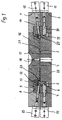
- the mould according to the invention comprises two halves 1, 2 one of them being moveable in an axial direction, whereas the other one is fixed.
- the half 1, bearing an injection nozzle 18 is fixed.
- a mirror 16 is held in said half 1 and a mirror ring 12 is attached to said mirror to limit a cavity 21. Said cavity is further limited by the mirror 16 and a bushing 17 held in said mirror 16 and being provided with the injection nozzle 18 as well as by a stamper 3 carrying the data to be stored on an optical data disc to be moulded within said cavity 21. Adjusting screws 13 are screwed into said mirror ring 12, used as a stop gauge for a stamper holder 5.
- Said mirror ring 12 is mounted within a ring 8 held in the half 1.
- actuating means e.g. pneumatic cylinders 15 are attached to move bolts 14.
- Said bolts are regularly displaced over the entire circumference of the half 1 and are guided in bores 9 passing in a radial plane through the half 1 and the ring 8.
- Said bolts 14 cooperate with a recess 20, built by a groove running in the circumferential direction of the stamp holder 5.
- the side walls of said groove 20 diverge toward the outer rims of said groove 20 and the end portion of the bolts 14 are provided with correspondingly inclined surfaces.
- the moveable half 2 is provided with a mirror 22 having a plane surface at which the stamper 3 rests.
- a central clamping 4 is inserted into a central bore of the mirror 22 and the stamper holder 5 surrounds the mirror 22 and is guided by its outer generated surface and is axially moveable along the mirror 22.
- Said stamper holder 5 is further guided within a ring 6 fastend to the half 2.
- actuator means 11 are attached to move further bolts 10 guided in radial planes within bores 7 passing through the half 1 and said ring 6.
- Said stamper holder 5 being provided with a further recess 19, built by a groove running also in the circumferential direction.
- Said groove 19 having outwardly diverging side walls, as is the case with the axially displaced groove 20 and the end portions of the bolts 10 are provided with correspondingly inclined surfaces.
- a plastizised material is injected into the cavity 21 via the injection nozzle 18.
- the stamper is fixed between the mirror 22 and the inwardly directed flange 23 of the stamper holder 5 and the stamper holder 5 is fixed with the bolts 10, whereby the mould is closed.
- the bolts 14, guided in the half 1 of the mould are retracted during the normal operation.
- the bolts 15 are retracted by the actuator means 15 and the moveable half 2 is moved away from the stationary half 1.
- the bolts 10 remains within the recess 19 of the stamp holder 5 to maintain the fixing of the stamper 3.
- the mould is closed after ejecting the moulded optical disc and the bolts 14 are inserted into the recess 20 of the stamp holder 5 (see Fig. 1). Now the bolts 10 are retracted whereas the bolts 14 remain within the recess 20.
- the stamper holder 5 After opening the mould the stamper holder 5 remains connected to the half 1 of the mould and the stamper 3 lays free at the mirror 22 and can be replaced by a new stamper 3 (Fig. 2). After closing the mould the bolts 10 are pushed into the recess 19 of the stamper holder 5 and the bolts 14 are retracted. A new injection moulding cycle can be started now with the new stamper 3.
Landscapes
- Engineering & Computer Science (AREA)
- Manufacturing & Machinery (AREA)
- Mechanical Engineering (AREA)
- Moulds For Moulding Plastics Or The Like (AREA)
- Manufacturing Optical Record Carriers (AREA)
- Mounting, Exchange, And Manufacturing Of Dies (AREA)
Abstract
Description
Claims (5)
- Injection mould for forming an optical data storage disc, said mould having two halves (1, 2) moveable one against another, the mould being provided with a stamper holder (5), comprising a body having a through bore and an inwardly directed flange used as a stop for an exchangeably held stamper (3), said stamper (3) having a complementary pattern of the data to be stored at the optical storage disc to be manufactured, and with a centre clamp (4) for holding said stamper (3) in the central region, one half (1) being provided with a mirror ring (7), limiting a cavity in co-operation with the stamper (3) and a mirror (16) bearing said mirror ring (7), when said mould is closed, and with an injection nozzle (18), characterised in that at least two axially moveable bolts (10, 14) are provided, said bolts (10, 14) are guided in different halves (1, 2) in a plane running essentially in a radial direction and said stamper holder (5) being provided with at least one recess (19, 20) at its outer generated surface, provided to receive said bolts (10, 14), whereby said stamper holder (5) is held during operation of the mould by at least said bolt(s) (10) guided in that half (2) opposite said injection nozzle (18).
- Mould according claim 1, characterized in that at least two axially displaced recesses (19, 20) are provided at the outer generated surface of said stamp holder (5).
- Mould according claim 1 or 2, characterised in that the recesses (9, 20) of the stamper holder (5) are built by grooves running in the circumferential direction of the stamp holder (5).
- Mould according one of the claims 1 to 3, characerised in that each half of the mould (1, 2) being provided with three bolts (10, 14) regularly displaced over the entire circumference of the stamper holder (5).
- Mould according one of the claims 1 to 4, characterised in that said recesses of the outer generated surface of the stamper holder (5) having outwardly diverging side walls in diametrical cross section and the bolts (10, 14) are provided with correspondingly shaped end regions co-operating with said recesses .
Priority Applications (3)
| Application Number | Priority Date | Filing Date | Title |
|---|---|---|---|
| DE69714212T DE69714212D1 (en) | 1997-04-17 | 1997-04-17 | Clamping device for a die for automatic switching |
| EP97890070A EP0872325B1 (en) | 1997-04-17 | 1997-04-17 | Stamper holder for automatic change-over |
| AT97890070T ATE220980T1 (en) | 1997-04-17 | 1997-04-17 | CLAMPING DEVICE OF A DIE FOR AUTOMATIC SWITCHING |
Applications Claiming Priority (1)
| Application Number | Priority Date | Filing Date | Title |
|---|---|---|---|
| EP97890070A EP0872325B1 (en) | 1997-04-17 | 1997-04-17 | Stamper holder for automatic change-over |
Publications (2)
| Publication Number | Publication Date |
|---|---|
| EP0872325A1 true EP0872325A1 (en) | 1998-10-21 |
| EP0872325B1 EP0872325B1 (en) | 2002-07-24 |
Family
ID=8231099
Family Applications (1)
| Application Number | Title | Priority Date | Filing Date |
|---|---|---|---|
| EP97890070A Expired - Lifetime EP0872325B1 (en) | 1997-04-17 | 1997-04-17 | Stamper holder for automatic change-over |
Country Status (3)
| Country | Link |
|---|---|
| EP (1) | EP0872325B1 (en) |
| AT (1) | ATE220980T1 (en) |
| DE (1) | DE69714212D1 (en) |
Citations (6)
| Publication number | Priority date | Publication date | Assignee | Title |
|---|---|---|---|---|
| EP0268291A2 (en) * | 1986-11-20 | 1988-05-25 | Kabushiki Kaisha Meiki Seisakusho | Mold for producing discs |
| GB2198985A (en) * | 1986-10-15 | 1988-06-29 | Gifu Husky Co | Mold or press having stamper holding apparatus |
| JPH0292608A (en) * | 1988-09-30 | 1990-04-03 | Sumitomo Heavy Ind Ltd | Mold for molding optical disc board |
| JPH02295725A (en) * | 1989-05-09 | 1990-12-06 | Seiko Giken:Kk | Mold apparatus for molding disc |
| JPH05285987A (en) * | 1992-04-08 | 1993-11-02 | Tekunopurasu:Kk | Outer periphery holding structure of disk molding stamper |
| JPH06166062A (en) * | 1992-11-30 | 1994-06-14 | Niigata Eng Co Ltd | Fixing device such as stamper in mold |
-
1997
- 1997-04-17 DE DE69714212T patent/DE69714212D1/en not_active Expired - Lifetime
- 1997-04-17 AT AT97890070T patent/ATE220980T1/en not_active IP Right Cessation
- 1997-04-17 EP EP97890070A patent/EP0872325B1/en not_active Expired - Lifetime
Patent Citations (6)
| Publication number | Priority date | Publication date | Assignee | Title |
|---|---|---|---|---|
| GB2198985A (en) * | 1986-10-15 | 1988-06-29 | Gifu Husky Co | Mold or press having stamper holding apparatus |
| EP0268291A2 (en) * | 1986-11-20 | 1988-05-25 | Kabushiki Kaisha Meiki Seisakusho | Mold for producing discs |
| JPH0292608A (en) * | 1988-09-30 | 1990-04-03 | Sumitomo Heavy Ind Ltd | Mold for molding optical disc board |
| JPH02295725A (en) * | 1989-05-09 | 1990-12-06 | Seiko Giken:Kk | Mold apparatus for molding disc |
| JPH05285987A (en) * | 1992-04-08 | 1993-11-02 | Tekunopurasu:Kk | Outer periphery holding structure of disk molding stamper |
| JPH06166062A (en) * | 1992-11-30 | 1994-06-14 | Niigata Eng Co Ltd | Fixing device such as stamper in mold |
Non-Patent Citations (4)
| Title |
|---|
| PATENT ABSTRACTS OF JAPAN vol. 14, no. 291 (M - 989)<4234> 22 June 1990 (1990-06-22) * |
| PATENT ABSTRACTS OF JAPAN vol. 15, no. 69 (M - 1083) 19 February 1991 (1991-02-19) * |
| PATENT ABSTRACTS OF JAPAN vol. 18, no. 496 (M - 1674) 16 September 1994 (1994-09-16) * |
| PATENT ABSTRACTS OF JAPAN vol. 18, no. 65 (M - 1554) 3 February 1994 (1994-02-03) * |
Also Published As
| Publication number | Publication date |
|---|---|
| EP0872325B1 (en) | 2002-07-24 |
| DE69714212D1 (en) | 2002-08-29 |
| ATE220980T1 (en) | 2002-08-15 |
Similar Documents
| Publication | Publication Date | Title |
|---|---|---|
| JPH0252716A (en) | Mold for molding optical disk base | |
| EP0268291B1 (en) | Mold for producing discs | |
| JP2713251B2 (en) | Injection mold | |
| US5607705A (en) | Mold for molding disc substrata | |
| US4531704A (en) | Injection molding machine | |
| US5702736A (en) | Assembly for manufacturing a piston from plastic material | |
| EP0872325B1 (en) | Stamper holder for automatic change-over | |
| KR100255341B1 (en) | Mold device for molding disk plate | |
| US5688537A (en) | Mold centering system for injection-molding machine | |
| EP0722818B1 (en) | Disc molding die | |
| US20040191352A1 (en) | Stamper holder, mold component, and mold assembly | |
| US20030068402A1 (en) | Injection mould and ejector arrangement therefor | |
| JP7651968B2 (en) | Injection mould | |
| JPH08276470A (en) | Injection mold | |
| JPH1170529A (en) | Mold for molding disk | |
| JPH0375022B2 (en) | ||
| JPH0723225Y2 (en) | Mold for molding | |
| JPH0153615B2 (en) | ||
| JPH0687140A (en) | Long roller and its manufacturing equipment | |
| JPH1015949A (en) | Mold for molding disk | |
| JP2000318005A (en) | Core compression injection molding machine | |
| JPH03230928A (en) | Mold unit for injection molding | |
| KR100220156B1 (en) | Disk moulding mould | |
| JP3167257B2 (en) | Mold for molding disk substrate and molding method | |
| JPH08169036A (en) | Injection mold equipment |
Legal Events
| Date | Code | Title | Description |
|---|---|---|---|
| PUAI | Public reference made under article 153(3) epc to a published international application that has entered the european phase |
Free format text: ORIGINAL CODE: 0009012 |
|
| AK | Designated contracting states |
Kind code of ref document: A1 Designated state(s): AT BE CH DE DK ES FI FR GB GR IE IT LI LU MC NL PT SE |
|
| AX | Request for extension of the european patent |
Free format text: LT;LV;SI |
|
| 17P | Request for examination filed |
Effective date: 19990421 |
|
| AKX | Designation fees paid |
Free format text: AT BE CH DE DK ES FI FR GB GR IE IT LI LU MC NL PT SE |
|
| AXX | Extension fees paid |
Free format text: LT PAYMENT 19990421;LV PAYMENT 19990421;SI PAYMENT 19990421 |
|
| 17Q | First examination report despatched |
Effective date: 20000725 |
|
| GRAG | Despatch of communication of intention to grant |
Free format text: ORIGINAL CODE: EPIDOS AGRA |
|
| GRAG | Despatch of communication of intention to grant |
Free format text: ORIGINAL CODE: EPIDOS AGRA |
|
| GRAH | Despatch of communication of intention to grant a patent |
Free format text: ORIGINAL CODE: EPIDOS IGRA |
|
| GRAH | Despatch of communication of intention to grant a patent |
Free format text: ORIGINAL CODE: EPIDOS IGRA |
|
| GRAA | (expected) grant |
Free format text: ORIGINAL CODE: 0009210 |
|
| AK | Designated contracting states |
Kind code of ref document: B1 Designated state(s): AT BE CH DE DK ES FI FR GB GR IE IT LI LU MC NL PT SE |
|
| AX | Request for extension of the european patent |
Free format text: LT PAYMENT 19990421;LV PAYMENT 19990421;SI PAYMENT 19990421 |
|
| PG25 | Lapsed in a contracting state [announced via postgrant information from national office to epo] |
Ref country code: NL Free format text: LAPSE BECAUSE OF FAILURE TO SUBMIT A TRANSLATION OF THE DESCRIPTION OR TO PAY THE FEE WITHIN THE PRESCRIBED TIME-LIMIT Effective date: 20020724 Ref country code: LI Free format text: LAPSE BECAUSE OF FAILURE TO SUBMIT A TRANSLATION OF THE DESCRIPTION OR TO PAY THE FEE WITHIN THE PRESCRIBED TIME-LIMIT Effective date: 20020724 Ref country code: IT Free format text: LAPSE BECAUSE OF FAILURE TO SUBMIT A TRANSLATION OF THE DESCRIPTION OR TO PAY THE FEE WITHIN THE PRE;WARNING: LAPSES OF ITALIAN PATENTS WITH EFFECTIVE DATE BEFORE 2007 MAY HAVE OCCURRED AT ANY TIME BEFORE 2007. THE CORRECT EFFECTIVE DATE MAY BE DIFFERENT FROM THE ONE RECORDED.SCRIBED TIME-LIMIT Effective date: 20020724 Ref country code: GR Free format text: LAPSE BECAUSE OF FAILURE TO SUBMIT A TRANSLATION OF THE DESCRIPTION OR TO PAY THE FEE WITHIN THE PRESCRIBED TIME-LIMIT Effective date: 20020724 Ref country code: FR Free format text: LAPSE BECAUSE OF NON-PAYMENT OF DUE FEES Effective date: 20020724 Ref country code: FI Free format text: LAPSE BECAUSE OF FAILURE TO SUBMIT A TRANSLATION OF THE DESCRIPTION OR TO PAY THE FEE WITHIN THE PRESCRIBED TIME-LIMIT Effective date: 20020724 Ref country code: CH Free format text: LAPSE BECAUSE OF FAILURE TO SUBMIT A TRANSLATION OF THE DESCRIPTION OR TO PAY THE FEE WITHIN THE PRESCRIBED TIME-LIMIT Effective date: 20020724 Ref country code: BE Free format text: LAPSE BECAUSE OF FAILURE TO SUBMIT A TRANSLATION OF THE DESCRIPTION OR TO PAY THE FEE WITHIN THE PRESCRIBED TIME-LIMIT Effective date: 20020724 |
|
| REF | Corresponds to: |
Ref document number: 220980 Country of ref document: AT Date of ref document: 20020815 Kind code of ref document: T |
|
| REG | Reference to a national code |
Ref country code: GB Ref legal event code: FG4D |
|
| REG | Reference to a national code |
Ref country code: CH Ref legal event code: EP |
|
| REG | Reference to a national code |
Ref country code: IE Ref legal event code: FG4D |
|
| REF | Corresponds to: |
Ref document number: 69714212 Country of ref document: DE Date of ref document: 20020829 |
|
| PG25 | Lapsed in a contracting state [announced via postgrant information from national office to epo] |
Ref country code: SE Free format text: LAPSE BECAUSE OF FAILURE TO SUBMIT A TRANSLATION OF THE DESCRIPTION OR TO PAY THE FEE WITHIN THE PRESCRIBED TIME-LIMIT Effective date: 20021024 Ref country code: PT Free format text: LAPSE BECAUSE OF FAILURE TO SUBMIT A TRANSLATION OF THE DESCRIPTION OR TO PAY THE FEE WITHIN THE PRESCRIBED TIME-LIMIT Effective date: 20021024 Ref country code: DK Free format text: LAPSE BECAUSE OF FAILURE TO SUBMIT A TRANSLATION OF THE DESCRIPTION OR TO PAY THE FEE WITHIN THE PRESCRIBED TIME-LIMIT Effective date: 20021024 |
|
| PG25 | Lapsed in a contracting state [announced via postgrant information from national office to epo] |
Ref country code: DE Free format text: LAPSE BECAUSE OF FAILURE TO SUBMIT A TRANSLATION OF THE DESCRIPTION OR TO PAY THE FEE WITHIN THE PRESCRIBED TIME-LIMIT Effective date: 20021025 |
|
| LTIE | Lt: invalidation of european patent or patent extension |
Effective date: 20020724 |
|
| NLV1 | Nl: lapsed or annulled due to failure to fulfill the requirements of art. 29p and 29m of the patents act | ||
| PG25 | Lapsed in a contracting state [announced via postgrant information from national office to epo] |
Ref country code: ES Free format text: LAPSE BECAUSE OF FAILURE TO SUBMIT A TRANSLATION OF THE DESCRIPTION OR TO PAY THE FEE WITHIN THE PRESCRIBED TIME-LIMIT Effective date: 20030130 |
|
| REG | Reference to a national code |
Ref country code: CH Ref legal event code: PL |
|
| EN | Fr: translation not filed | ||
| PG25 | Lapsed in a contracting state [announced via postgrant information from national office to epo] |
Ref country code: LU Free format text: LAPSE BECAUSE OF NON-PAYMENT OF DUE FEES Effective date: 20030417 Ref country code: IE Free format text: LAPSE BECAUSE OF NON-PAYMENT OF DUE FEES Effective date: 20030417 Ref country code: GB Free format text: LAPSE BECAUSE OF NON-PAYMENT OF DUE FEES Effective date: 20030417 |
|
| PG25 | Lapsed in a contracting state [announced via postgrant information from national office to epo] |
Ref country code: MC Free format text: LAPSE BECAUSE OF NON-PAYMENT OF DUE FEES Effective date: 20030430 |
|
| PLBE | No opposition filed within time limit |
Free format text: ORIGINAL CODE: 0009261 |
|
| STAA | Information on the status of an ep patent application or granted ep patent |
Free format text: STATUS: NO OPPOSITION FILED WITHIN TIME LIMIT |
|
| 26N | No opposition filed |
Effective date: 20030425 |
|
| GBPC | Gb: european patent ceased through non-payment of renewal fee |
Effective date: 20030417 |
|
| REG | Reference to a national code |
Ref country code: IE Ref legal event code: MM4A |
|
| PGFP | Annual fee paid to national office [announced via postgrant information from national office to epo] |
Ref country code: AT Payment date: 20100415 Year of fee payment: 14 |
|
| REG | Reference to a national code |
Ref country code: AT Ref legal event code: MM01 Ref document number: 220980 Country of ref document: AT Kind code of ref document: T Effective date: 20110417 |
|
| PG25 | Lapsed in a contracting state [announced via postgrant information from national office to epo] |
Ref country code: AT Free format text: LAPSE BECAUSE OF NON-PAYMENT OF DUE FEES Effective date: 20110417 |