EP0871857B1 - Dispositif optique de detection de caracteristiques de particules en mouvement - Google Patents
Dispositif optique de detection de caracteristiques de particules en mouvement Download PDFInfo
- Publication number
- EP0871857B1 EP0871857B1 EP96901379A EP96901379A EP0871857B1 EP 0871857 B1 EP0871857 B1 EP 0871857B1 EP 96901379 A EP96901379 A EP 96901379A EP 96901379 A EP96901379 A EP 96901379A EP 0871857 B1 EP0871857 B1 EP 0871857B1
- Authority
- EP
- European Patent Office
- Prior art keywords
- substrate
- guides
- optic
- guide
- detection
- Prior art date
- Legal status (The legal status is an assumption and is not a legal conclusion. Google has not performed a legal analysis and makes no representation as to the accuracy of the status listed.)
- Expired - Lifetime
Links
- 239000002245 particle Substances 0.000 title claims description 26
- 230000003287 optical effect Effects 0.000 title description 31
- 239000000758 substrate Substances 0.000 claims description 48
- 238000001514 detection method Methods 0.000 claims description 19
- 239000012530 fluid Substances 0.000 claims description 14
- 238000000034 method Methods 0.000 claims description 10
- 238000012545 processing Methods 0.000 claims description 10
- 230000007704 transition Effects 0.000 claims description 9
- 230000005693 optoelectronics Effects 0.000 claims description 5
- 230000001427 coherent effect Effects 0.000 claims description 4
- 238000005259 measurement Methods 0.000 description 33
- 239000011521 glass Substances 0.000 description 4
- 238000004519 manufacturing process Methods 0.000 description 4
- 238000005342 ion exchange Methods 0.000 description 3
- 239000013307 optical fiber Substances 0.000 description 3
- 230000000694 effects Effects 0.000 description 2
- 230000010363 phase shift Effects 0.000 description 2
- 238000000827 velocimetry Methods 0.000 description 2
- XUIMIQQOPSSXEZ-UHFFFAOYSA-N Silicon Chemical compound [Si] XUIMIQQOPSSXEZ-UHFFFAOYSA-N 0.000 description 1
- 238000004026 adhesive bonding Methods 0.000 description 1
- 238000013459 approach Methods 0.000 description 1
- 235000019993 champagne Nutrition 0.000 description 1
- 238000013461 design Methods 0.000 description 1
- 238000011161 development Methods 0.000 description 1
- 238000005530 etching Methods 0.000 description 1
- 239000000835 fiber Substances 0.000 description 1
- 230000004907 flux Effects 0.000 description 1
- 238000002513 implantation Methods 0.000 description 1
- 238000009434 installation Methods 0.000 description 1
- 230000002452 interceptive effect Effects 0.000 description 1
- 150000002500 ions Chemical class 0.000 description 1
- 238000011545 laboratory measurement Methods 0.000 description 1
- 239000007788 liquid Substances 0.000 description 1
- 239000004973 liquid crystal related substance Substances 0.000 description 1
- 238000004599 local-density approximation Methods 0.000 description 1
- 238000012986 modification Methods 0.000 description 1
- 230000004048 modification Effects 0.000 description 1
- 230000003071 parasitic effect Effects 0.000 description 1
- 230000008569 process Effects 0.000 description 1
- 229910052710 silicon Inorganic materials 0.000 description 1
- 239000010703 silicon Substances 0.000 description 1
- 238000010183 spectrum analysis Methods 0.000 description 1
Images




Classifications
-
- G—PHYSICS
- G01—MEASURING; TESTING
- G01N—INVESTIGATING OR ANALYSING MATERIALS BY DETERMINING THEIR CHEMICAL OR PHYSICAL PROPERTIES
- G01N15/00—Investigating characteristics of particles; Investigating permeability, pore-volume or surface-area of porous materials
- G01N15/02—Investigating particle size or size distribution
- G01N15/0205—Investigating particle size or size distribution by optical means
-
- G—PHYSICS
- G01—MEASURING; TESTING
- G01P—MEASURING LINEAR OR ANGULAR SPEED, ACCELERATION, DECELERATION, OR SHOCK; INDICATING PRESENCE, ABSENCE, OR DIRECTION, OF MOVEMENT
- G01P5/00—Measuring speed of fluids, e.g. of air stream; Measuring speed of bodies relative to fluids, e.g. of ship, of aircraft
- G01P5/26—Measuring speed of fluids, e.g. of air stream; Measuring speed of bodies relative to fluids, e.g. of ship, of aircraft by measuring the direct influence of the streaming fluid on the properties of a detecting optical wave
-
- G—PHYSICS
- G01—MEASURING; TESTING
- G01N—INVESTIGATING OR ANALYSING MATERIALS BY DETERMINING THEIR CHEMICAL OR PHYSICAL PROPERTIES
- G01N15/00—Investigating characteristics of particles; Investigating permeability, pore-volume or surface-area of porous materials
- G01N15/10—Investigating individual particles
- G01N15/14—Optical investigation techniques, e.g. flow cytometry
- G01N15/1434—Optical arrangements
- G01N2015/1447—Spatial selection
- G01N2015/145—Spatial selection by pattern of light, e.g. fringe pattern
-
- G—PHYSICS
- G01—MEASURING; TESTING
- G01S—RADIO DIRECTION-FINDING; RADIO NAVIGATION; DETERMINING DISTANCE OR VELOCITY BY USE OF RADIO WAVES; LOCATING OR PRESENCE-DETECTING BY USE OF THE REFLECTION OR RERADIATION OF RADIO WAVES; ANALOGOUS ARRANGEMENTS USING OTHER WAVES
- G01S17/00—Systems using the reflection or reradiation of electromagnetic waves other than radio waves, e.g. lidar systems
- G01S17/02—Systems using the reflection of electromagnetic waves other than radio waves
- G01S17/50—Systems of measurement based on relative movement of target
- G01S17/58—Velocity or trajectory determination systems; Sense-of-movement determination systems
Definitions
- the invention relates to an optical device for detecting the characteristics of particles in movement in a fluid flowing along a wall, device comprising a source light, means, connected to the light source, for producing at least two mutually coherent light beams forming between them a predetermined angle of so as to form an interference zone constituting a measurement volume on the path of the fluid, optical means for detecting the light scattered by particles passing through the measurement volume, optoelectronic detection means, connected to the means detection optics and providing electronic signals representative of light broadcast, and processing means, connected to the detection means optoelectronics.
- a device is known from document WO-A-84 045 92.
- Doppler laser velocimeter to measure particle velocity submicrones in a fluid. Such a velocimeter is based on the crossing by particles of a succession of dark and bright equidistant zones belonging to a network of interference fringes.
- Figure 1 illustrates the principle of Doppler laser velocimetry using the method fringes.
- Two coherent light beams 1 and 2 coming from the same laser 3, are intersect at the focal point of a converging lens 4, inside a measurement volume 5.
- the Figure 2 shows in more detail the measurement volume 5.
- Inside the measurement volume 5 appears a system of interference fringes arranged in equidistant planes, parallel to the interior bisector of the two beams 1 and 2. The distance between two planes is the interfrange i.
- a particle, entrained by a moving fluid perpendicular to the fringes (axis X'X of figure 2, arrow 6 of figure 1), cross the measurement volume 5 and passes successively through the dark and shiny fringes.
- the luminous flux diffused by a particle is modulated at a frequency proportional to its movement speed.
- the light scattered by a particle is collected by a device optical detection.
- the scattered light is generally measured by back scattering, that is to say on the side of the emission source constituted by the laser 3, as shown in the Figure 1.
- the detection device has a fairly large objective 7 for collect the light scattered by the particles and form the image of the measurement volume on a diaphragm located in front of a photo-multiplier 8.
- This provides a circuit electronics for processing 9 electrical signals representative of the light scattered by the particles.
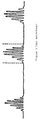
- the signals supplied to the processing circuit 9 are in the form of a succession of sinusoid trains, as shown in FIG. 3.
- Each of the trains is due to the passage of a particle in the measurement volume 5.
- the frequency of a sinusoid train is representative of the speed of the corresponding particle in the measurement volume.
- the processing circuit performs frequency analysis of signals.
- Known treatment techniques use spectral analysis, frequency trackers or image correlation. These various techniques make it possible to obtain average values of the speed of a particle. Of counting techniques make it possible to obtain instantaneous values of the velocity of a particle.
- Doppler laser velocimetry has so far been reserved for laboratory measurements.
- Known velocimeters are expensive and require difficult adjustments, in particular the adjustment of angle A (figure 1) of beams 1 and 2. Indeed, a modification of angle A modifies the interfrange i and, consequently, the frequency of the measured signals.
- the device optical detection devices must also be carefully aligned.
- the Doppler effect velocimeter has been used more particularly for the velocity measurement of particles in a fluid or, indirectly, for the measurement of friction, near a wall.
- a wall section is transparent.
- the light beams arrive on the wall with a low incidence and the signals collected are very noisy due to reflections of light on the walls. Only long and delicate optical adjustments, impractical in industrial environment, allow, in laboratory, to obtain acceptable signal / noise ratios.
- the object of the invention is an optical device for detecting the characteristics of particles in movement, inexpensive and industrially feasible.
- the means for producing beams comprise at least one pair of two emitting optical guides
- the optical means for detection comprise at least one receiving optical guide having one end input having an axis passing through the center of the measurement volume
- said emitter guides and receivers being produced on a single substrate, by integrated optics techniques, the geometry of the emitter guides being such that the measurement volume is arranged outside from the substrate, at a predetermined distance from one face of the substrate, the substrate being mounted in a support intended to be fixed in an opening in the wall so that said face of the substrate is in contact with the fluid.
- the device uses the principle of laser Doppler velocimetry, and includes a fully integrated optical system intended to be implanted in a wall which can be opaque.
- the substrate comprises a planar guide between the guides emitting optics and said face of the substrate.
- the beams produced by the emitting optical guides can be beams parallel, obtained by an adiabatic transition formed at the end of the emitting guides, or converging beams.
- FIG. 1 represents a laser velocimeter with Doppler effect according to the prior art.
- FIG. 2 represents in greater detail the measurement volume of the velocimeter of FIG. 1.
- FIG. 3 represents the signals transmitted to the electronic circuit for processing the velocimeter according to figure 1.
- FIG. 4 schematically represents a device according to the invention comprising a optical head implanted in an opaque wall.
- FIG. 5 to 8 and 10 show various particular embodiments of the head optics of the device according to FIG. 4.
- FIG. 9 illustrates a mask intended for manufacturing an optical head according to FIG. 8.
- the device according to FIG. 4 comprises an optical head 10 connected to a laser 3 and to a optoelectronic detection circuit 11. Circuit 11 is connected to the processing circuit 9.
- the optical head 10 is essentially constituted by a substrate 12 on which guides optics, or micro-guides, are formed by integrated optics techniques.
- Guides optical transmitters are connected by an optical fiber 13 to an optical source, consisting for example by a laser 3. They are designed so as to provide two optical beams coherents 1 and 2, which converge at a measurement point P located outside the substrate, to form stable interference fringes at this point.
- Interfringe i is defined by the wavelength of the laser and by the angle A of the beams 1 and 2.
- Optical guides receivers transmit to the detection circuit 11, via an optical fiber 14, signals representative of the light scattered by particles passing through the fringes interference.
- the substrate 12 is preferably a glass substrate on which the optical guides are made by ion exchange.
- the substrate 12 can have a length of the order of a few centimeters, 6cm for example, a width and a thickness of the order of a few hundred micrometers, for example 0.5mm.
- the substrate is carried by a support 15 so as to form the optical head 10, compact and waterproof, which can be installed in a wall 16.
- the device thus makes it possible to study particles moving in a fluid flowing (arrow 6) along the wall 16.
- the measurement volume which is assimilated to a point P in the figure, is defined by the beams 1 and 2.
- the position of the point P relative to the face 17 of the substrate 12 in contact with the fluid is precisely determined by the geometry of the optical guides installed in the substrate. This position is defined by the angle A and by the distance between the points of exit of beams 1 and 2 from the substrate.
- the substrate is mounted in the support 15 so that its face 17 is in contact with the fluid, preferably aligned with the internal face of the wall 16.
- the position of the measurement point P is thus precisely defined and it is possible to approach very close to the wall 16, less than a hundred micrometers, while maintaining good signal quality.
- FIG. 5 illustrates the arrangement of the guides on the substrate 12 according to a particular mode of production.
- a guide 18, an input emitter guide, is formed on the substrate.
- a separator of beam 19, constituted by a Y junction, divides it into a pair of two guides transmitters 20 and 21.
- An adiabatic transition 22 is produced at the end of the guide 20 leading to face 17. This adiabatic transition widens the beam transmitted by the guide 20 so that the light beam 1 is a parallel beam.
- a adiabatic transition is also carried out at the end of the guide 21 so as to form a parallel light beam 2.
- the ends of the guides 20 and 21 are inclined relative to each other, so that that the beams 1 and 2 converge at a predetermined point P, located outside the substrate, making a predetermined angle A between them.
- a receiving guide 23 is formed on the substrate 12. It has a first end, at the inlet, which opens onto the face 17 of the substrate so that the axis 24 of this first end passes through the measurement point P. A second end, guide 23 is intended to be connected to the detection circuit 11.
- the quantity of light scattered by a particle passing through the interference fringes at point P is very low, for example of the order of a few nanowatts for a laser of one watt. It is therefore desirable to receive in the receiving guide 23 the maximum of light for facilitate further processing of signals.
- the guide 23 is perpendicular to the face 17 of the substrate so as to optimize the amount of light received.
- the width of the guide 23 is determined so as to receive a maximum amount of light, while delimiting the portion of the volume of measure reviewed.
- the guide 23 is rectilinear. It can be formed in the same plane as the guides 20 and 21 or in a different plane ( Figure 8).
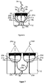
- two pairs of transmitter guides define two measurement points Pa and Pb aligned on the axis 24 of the inlet end of the receiver guide 23.
- Each of the points of measurement is defined, as in figure 5, by an input transmitter guide, respectively 18a and 18b, divided (junctions 19a and 19b) into a pair of two transmitter guides (20a and 21a; 20b and 21b) whose ends are widened, at 22, to form parallel beams (1a and 2a; 1b and 2b).
- the receiver guide 23 is unique and makes it possible to observe the two points Pa and Pb. To allow to differentiate the signals coming from the two points these are illuminated sequentially.
- the light signals applied the input transmitter guides 18a and 18b respectively are for example multiplexed.
- the multiplexing can be carried out at the optical source, which then comprises two outputs respectively connected by two separate optical fibers to guides 18a and 18b and activated sequentially.
- two pairs of transmitter guides define two measurement points, Pc and Pd, offset laterally.
- the pairs of transmitter guides have an input guide common 18.
- a junction Y 25 divides the guide 18 into two intermediate guides 26c and 26d. Each intermediate guide is then divided by a corresponding Y junction, 19c or 19d, in a pair of two transmitter guides (20c and 21c or 20d and 21d) defining a measuring point (Pc or Pd).
- Two receiving guides 23c and 23d are arranged so as to receive the light scattered at points Pc and Pd respectively.
- the end axis 24c of the receiver guide 23c passes through the point Pc and the axis 24d of the inlet end of the receiver guide 23d passes through point Pd.
- the signals from the points Pc and Pd are collected separately. If the receiver guides 23c and 23d are connected separately to the detection circuit 11, electronic multiplexing can be carried out at the detection circuit level 11.
- the multiplexing of transmitter beams can be produced in the optical head 10 itself.
- a modulator, or switch, optical is arranged in the path of each pair of transmitter guides.
- Such modulator is for example formed by a deposit of liquid crystals or by process thermooptical when the substrate 12 is a glass substrate.
- FIG. 8 represents, on a larger scale, the parallel beams 1 and 2 which converge so as to define the measurement volume 5 in which the fringes are formed interference.
- the transmitter guides are symmetrical with respect to the axis 24 of the receiving guide 23.
- the adiabatic transitions ends of the beams 20 and 21 form the parallel beams 1 and 2.
- a planar guide 27 of exit is formed at the exit of adiabatic transitions 22 to face 17, of so that the beams propagate freely in the substrate before interfering with the exterior of the substrate in volume 5.
- the angle A is defined by the geometry of the ends of guides 20, 21 and their transitions 22.
- a mask 28 shown in FIG. 9 makes it possible to reproduce the guides very precisely. emitters of the optical head of figure 8.
- the mask reproduces very exactly the geometry of guides 18, 20 and 21 and adiabatic transitions 22. It ends with a flat part intended to form the plan guide 27. This part at a height h such that the interference of the beams 1 and 2 takes place outside of the planar guide 27.
- the mask is placed on the substrate and then removed after implantation of ions.
- the substrate 12 is sawn and polished in the part forming the planar guide 27 so as to form the face 17 at a predetermined distance from the measurement volume 5. It is thus possible, from the same mask, to form optical heads defining measuring points at different distances from the face 17.
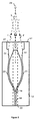
- the measurement volume, at point P is defined by means of two converging beams le and 2e which intersect at point P.
- the measurement volume can thus be reduced than when using parallel beams of the previously described embodiments.
- the measurement volume can have a diameter of the order of 100 micrometers with beams parallel and can be of the order of 20 to 30 micrometers with converging beams.
- Each converging beam, the 2nd or 2nd is formed by a curved mirror, respectively 30 or 31, the focal point of which is at point P, in the center of the measurement volume.
- the beam light emerging from the guide 20 is reflected by the curved mirror 30 so as to form the beam converging passing through point P.
- the light beam leaving the guide 21 is reflected by the curved mirror 31 to form the 2nd passing convergent beam also by point P.
- the intersection of the two beams at point P forms the fringes interference of the measurement volume.
- the curved mirrors 30 and 31 can be produced very simply by giving a shape specific to the edge of a plane guide 32 of exit, so as to ensure a total reflection output beams of guides 20 and 21.
- this is done very simply by giving a shape suitable for the mask in the part intended to form the exit plane guide.
- the substrate 12 can also be a silicon substrate. Curved mirrors 30 and 31 can then be produced by etching the substrate and metallizing the external face of the mirrors.
- the input emitter guide 18 is placed in the axis of symmetry of the substrate 12, coincident with the axis 24 of the inlet end of the receiver guide 23.
- the latter could, as in FIG. 8 be rectilinear, arranged in another plane of the substrate 12 than the transmitter guides. In figure 10, it is located in the same plane, but its end of output is offset to allow connection to detection circuit 11.
- the fibers 13 and 14 (FIG. 4), connected respectively to the input of the emitter guide 18 and at the outlet of the receiver guide 23, can be connected to the micro-guides by gluing.
- the use of a glass substrate is particularly advantageous because it has a very low intrinsic attenuation, is inexpensive and available in large sizes, which allows design devices several centimeters in length.
- the technique ion exchange for the production of micro-guides, with the use of a mask allows an easy and very precise reproduction of a predetermined model.
- the network of interference fringes is characterized by the spatial spacing of the fringes which depends on both the wavelength of the input light beam supplied by the laser and the inclination of the axes of the light beams 1 and 2 delimiting the measurement volume.
- the position of the interference fringes depends on a possible phase difference existing between the two arms of the interferometer constituted by the guides 20, 21.
- the arms (guides 20, 21) are equal (fig. 8 and 10) or substantially equal (fig. 5 to 7) and the fringes are practically centered with respect to the measurement volume.
- a current modulation of the laser 3 or a variation of the phase shift then allows to scroll the fringes in the direction 6 of fluid flow ( Figure 4). This can, if necessary, allow the sign of the direction of flow to be detected.
- the measurement of the frequency of the signals inside a train of sinusoids makes it possible to obtain a quantity representative of the speed of the moving particles in the measurement volume 5.
- the frequency of the sinusoids can be used to measure the number of particles. Otherwise, the envelope of a train of sinusoids is representative of the size of the particle corresponding.
- Data processing can be done in any known way and will not be not explained in more detail.
- the above integrated device allows easy installation and disassembly in a wall 16.
- the device is both robust and compact. It does not disturb the fluid flowing along the wall 16, because the device does not protrude inside of the wall. Since the light signals do not have to pass through the wall, the device eliminates the parasitic reflections which would be due to such a crossing and the disturbances due to these stray reflections. In addition, no optical adjustment is necessary, which allows a very easy to use in an industrial environment.
- Such a device is more particularly suitable for determining the speed, the size and the number of particles moving in a liquid.
- Applications are possible for example in the food industry (ex: champagne bubbles), in chemistry and in biology.
- the angle A of the beams 1 and 2, on which the fringe i depends, is predetermined by taking account of the intended application and in particular the size of the particles to be examined.
Landscapes
- Chemical & Material Sciences (AREA)
- Engineering & Computer Science (AREA)
- Physics & Mathematics (AREA)
- General Physics & Mathematics (AREA)
- Biochemistry (AREA)
- Analytical Chemistry (AREA)
- Life Sciences & Earth Sciences (AREA)
- General Health & Medical Sciences (AREA)
- Health & Medical Sciences (AREA)
- Immunology (AREA)
- Pathology (AREA)
- Dispersion Chemistry (AREA)
- Multimedia (AREA)
- Aviation & Aerospace Engineering (AREA)
- Investigating Or Analysing Materials By Optical Means (AREA)
Description
Claims (10)
- Dispositif optique de détection de caractéristiques de particules en mouvement dans un fluide s'écoulant le long d'une paroi (16), dispositif comportant une source lumineuse (3), des moyens, connectés à la source lumineuse, de production d'au moins deux faisceaux lumineux (1, 2) mutuellement cohérents formant entre eux un angle prédéterminé (A) de manière à former une zone d'interférence constituant un volume de mesure (5, P,) sur le trajet (6) du fluide, des moyens optiques (23) de détection de la lumière diffusée par des particules traversant le volume de mesure (5), des moyens (11) de détection optoélectroniques, connectés aux moyens optiques de détection et fournissant des signaux électroniques représentatifs de la lumière diffusée, et des moyens (9) de traitement, connectés aux moyens de détection optoélectroniques, dispositif caractérisé en ce que les moyens de production de faisceaux comportent au moins une paire de deux guides optiques émetteurs (20, 21), les moyens optiques de détection comportent au moins un guide optique récepteur (23) comportant une extrémité d'entrée ayant un axe (24) passant par le centre du volume de mesure (5, P), lesdits guides émetteurs et récepteurs étant réalisés sur un substrat unique (12), par des techniques d'optique intégrée, la géométrie des guides émetteurs étant telle que le volume de mesure (5, P) soit disposé à l'extérieur du substrat, à un distance prédéterminée d'une face (17) du substrat, le substrat étant monté dans un support (15) destiné à être fixé dans un orifice de la paroi (16) de manière à ce que ladite face (17) du substrat soit en contact avec le fluide.
- Dispositif selon la revendication 1, caractérisé en ce que le substrat (12) comporte un guide plan (27, 32) entre les guides optiques émetteurs (20, 21) et ladite face (17) du substrat.
- Dispositif selon l'une des revendications 1 et 2, caractérisé en ce que les guides optiques émetteurs (20, 21) comportent chacun, à une extrémité, une transition adiabatique (22) constituée par un élargissement de l'extrémité du guide optique émetteur (20, 21) de manière à former des faisceaux (1, 2) parallèles.
- Dispositif selon la revendication 2, caractérisé en ce que le guide plan comporte des moyens de formation de faisceaux (1, 2) convergents.
- Dispositif selon la revendication 4, caractérisé en ce que les moyens de formation de faisceaux convergents comportent des miroirs courbes (30, 31) ayant des points focaux au centre du volume de mesure (5, P).
- Dispositif selon l'une quelconque des revendications 1 à 5 caractérisé en ce que le substrat (12) comporte une pluralité de paires de guides optiques émetteurs de manière à définir une pluralité de volumes de mesure (Pa, Pb ; Pc, Pd)
- Dispositif selon la revendication 6 caractérisé en ce que les volumes de mesure (Pa, Pb) sont alignés avec l'axe (24) de l'extrémité d'entrée d'un guide récepteur unique (24).
- Dispositif selon la revendication 6 caractérisé en ce que les volumes de mesure (Pc, Pd) sont décalés latéralement, le substrat (12) comportant une pluralité de guides récepteurs associés (23c, 23d) décalés latéralement et ayant des axes (24c, 24d) passant respectivement par le centre du volume de mesure associé.
- Dispositif selon l'une quelconque des revendication 1 à 8, caractérisé en ce que les guides optiques récepteurs (23) sont réalisés dans le substrat (12) dans un plan différent des guides optiques émetteurs (20, 21).
- Dispositif selon l'une quelconque des revendications 1 à 9, caractérisé en ce qu'il comporte des moyens produisant un défilement des franges d'interférence dans la zone d'interférence.
Applications Claiming Priority (3)
| Application Number | Priority Date | Filing Date | Title |
|---|---|---|---|
| FR9408523A FR2722290B1 (fr) | 1994-07-07 | 1994-07-07 | Dispositif optique de detection de caracteristiques de particules en mouvement |
| CA002241282A CA2241282C (fr) | 1994-07-07 | 1996-01-11 | Appareil optique de detection des particularites de particules en mouvement |
| PCT/FR1996/000048 WO1997025607A1 (fr) | 1994-07-07 | 1996-01-11 | Dispositif optique de detection de caracteristiques de particules en mouvement |
Publications (2)
| Publication Number | Publication Date |
|---|---|
| EP0871857A1 EP0871857A1 (fr) | 1998-10-21 |
| EP0871857B1 true EP0871857B1 (fr) | 2000-04-12 |
Family
ID=27170738
Family Applications (1)
| Application Number | Title | Priority Date | Filing Date |
|---|---|---|---|
| EP96901379A Expired - Lifetime EP0871857B1 (fr) | 1994-07-07 | 1996-01-11 | Dispositif optique de detection de caracteristiques de particules en mouvement |
Country Status (3)
| Country | Link |
|---|---|
| EP (1) | EP0871857B1 (fr) |
| DE (1) | DE69607769T2 (fr) |
| WO (1) | WO1997025607A1 (fr) |
Families Citing this family (1)
| Publication number | Priority date | Publication date | Assignee | Title |
|---|---|---|---|---|
| DE202017006886U1 (de) | 2017-04-26 | 2018-10-17 | Jenoptik Industrial Metrology Germany Gmbh | Konturmessgerät |
Family Cites Families (7)
| Publication number | Priority date | Publication date | Assignee | Title |
|---|---|---|---|---|
| ATE29071T1 (de) * | 1983-05-18 | 1987-09-15 | Dantec Elektronik Med | Laserdoppler-vorrichtung zur bestimmung der groesse sich bewegender teilchen in einem fluessigkeitsdebit. |
| US4540283A (en) * | 1983-06-20 | 1985-09-10 | Bachalo William D | Apparatus and method for determining the size and velocity of particles, droplets, bubbles or the like using laser light scattering |
| EP0184269B1 (fr) * | 1984-12-04 | 1990-08-08 | The Dow Chemical Company | Capteur à fibres optiques et procédé pour déterminer la taille et/ou la concentration de substances en suspension |
| GB8727767D0 (en) * | 1987-11-27 | 1987-12-31 | Ahmed N E A | Improvements in or relating to velocimeters |
| US5094526A (en) * | 1990-11-07 | 1992-03-10 | General Signal Corporation | Integrated optical waveguide doppler velocimeter |
| DE4240769C2 (de) * | 1992-12-03 | 1997-04-10 | Invent Gmbh | Verfahren und Vorrichtung zur Erfassung mehrerer Geschwindigkeitskomponenten, insbesondere von Teilchen in Fluiden |
| DE4326979C2 (de) * | 1993-08-11 | 1998-02-12 | Dantec Invent Measurement Tech | Laser-Doppler-Gerät sowie Verfahren zum Betreiben eines solchen Gerätes |
-
1996
- 1996-01-11 DE DE69607769T patent/DE69607769T2/de not_active Expired - Lifetime
- 1996-01-11 WO PCT/FR1996/000048 patent/WO1997025607A1/fr not_active Ceased
- 1996-01-11 EP EP96901379A patent/EP0871857B1/fr not_active Expired - Lifetime
Also Published As
| Publication number | Publication date |
|---|---|
| WO1997025607A1 (fr) | 1997-07-17 |
| DE69607769T2 (de) | 2000-09-28 |
| EP0871857A1 (fr) | 1998-10-21 |
| DE69607769D1 (de) | 2000-05-18 |
Similar Documents
| Publication | Publication Date | Title |
|---|---|---|
| EP0015820B1 (fr) | Dispositif pour la mesure des vitesses linéaires sans contact et sans marquage | |
| FR2613826A1 (fr) | Capteur de deplacement en optique integree | |
| EP0406058A1 (fr) | Dispositif de mesure de la vitesse du vent à moyenne altitude | |
| EP0227556A1 (fr) | Capteur optique de grandeurs physiques | |
| EP0675348B1 (fr) | Dispositif de mesure optique de température cryogénique | |
| EP0512919A1 (fr) | Dispositif de mesure à distance de la position d'un objet | |
| WO2018138223A1 (fr) | Détecteur optique de particules | |
| FR2581206A1 (fr) | Transducteur optique a fibre optique | |
| EP3201610B1 (fr) | Procédé et système d'inspection de plaquettes transparentes pour l'électronique, l'optique ou l'optoélectronique | |
| EP0846274B1 (fr) | Sonde velocimetrique optique | |
| EP0971203B1 (fr) | Procédé et dispositif pour la mesure de l'épaisseur d'un matériau transparent | |
| FR2722290A1 (fr) | Dispositif optique de detection de caracteristiques de particules en mouvement | |
| EP4575463B1 (fr) | Dispositif de mesure de l'indice de refraction d'un fluide | |
| EP0871857A1 (fr) | Dispositif optique de detection de caracteristiques de particules en mouvement | |
| EP3583402B1 (fr) | Detecteur optique de particules et procede de fabrication d'un detecteur de particules | |
| FR3076611A1 (fr) | Dispositif de mesure pour surveiller le niveau de remplissage et effectuer les mesures différentielles de l’indice de réfraction optique | |
| FR2780167A1 (fr) | Dispositif pour produire des faisceaux de rayons paralleles collimates a partir de diodes laser a couplage de fibres et procede de fabrication de ce dispositif | |
| EP1105712B1 (fr) | Dispositif de mesure de la taille de particules en deplacement, notamment pour des mesures pluviometriques | |
| WO2013140065A1 (fr) | Système de mesure d'une zone d'écartement dans un substrat | |
| FR2720839A1 (fr) | Vélocimètre laser à effet doppler portable. | |
| US6654123B2 (en) | Sensor utilizing attenuated total reflection | |
| EP0347298A2 (fr) | Procédé et dispositif de mesure de la visibilité à travers un milieu d'opacité variable | |
| FR2725788A1 (fr) | Refractometre a fibre optique realise en optique guidee | |
| WO2000006995A1 (fr) | Procede et dispositif optique pour la mesure des caracteristiques dynamiques d'un milieu gazeux | |
| WO2026104188A1 (fr) | Système optique de télédétection hétérodyne |
Legal Events
| Date | Code | Title | Description |
|---|---|---|---|
| PUAI | Public reference made under article 153(3) epc to a published international application that has entered the european phase |
Free format text: ORIGINAL CODE: 0009012 |
|
| 17P | Request for examination filed |
Effective date: 19980619 |
|
| AK | Designated contracting states |
Kind code of ref document: A1 Designated state(s): DE GB IT |
|
| GRAG | Despatch of communication of intention to grant |
Free format text: ORIGINAL CODE: EPIDOS AGRA |
|
| 17Q | First examination report despatched |
Effective date: 19990607 |
|
| RAP1 | Party data changed (applicant data changed or rights of an application transferred) |
Owner name: SCHNEIDER ELECTRIC INDUSTRIES SA |
|
| GRAG | Despatch of communication of intention to grant |
Free format text: ORIGINAL CODE: EPIDOS AGRA |
|
| GRAH | Despatch of communication of intention to grant a patent |
Free format text: ORIGINAL CODE: EPIDOS IGRA |
|
| GRAH | Despatch of communication of intention to grant a patent |
Free format text: ORIGINAL CODE: EPIDOS IGRA |
|
| GRAA | (expected) grant |
Free format text: ORIGINAL CODE: 0009210 |
|
| RAP1 | Party data changed (applicant data changed or rights of an application transferred) |
Owner name: SCHNEIDER ELECTRIC INDUSTRIES SA |
|
| AK | Designated contracting states |
Kind code of ref document: B1 Designated state(s): DE GB IT |
|
| REF | Corresponds to: |
Ref document number: 69607769 Country of ref document: DE Date of ref document: 20000518 |
|
| GBT | Gb: translation of ep patent filed (gb section 77(6)(a)/1977) |
Effective date: 20000519 |
|
| ITF | It: translation for a ep patent filed | ||
| PLBE | No opposition filed within time limit |
Free format text: ORIGINAL CODE: 0009261 |
|
| STAA | Information on the status of an ep patent application or granted ep patent |
Free format text: STATUS: NO OPPOSITION FILED WITHIN TIME LIMIT |
|
| 26N | No opposition filed | ||
| REG | Reference to a national code |
Ref country code: GB Ref legal event code: IF02 |
|
| PGFP | Annual fee paid to national office [announced via postgrant information from national office to epo] |
Ref country code: IT Payment date: 20120112 Year of fee payment: 17 |
|
| PGFP | Annual fee paid to national office [announced via postgrant information from national office to epo] |
Ref country code: DE Payment date: 20130115 Year of fee payment: 18 Ref country code: GB Payment date: 20130109 Year of fee payment: 18 |
|
| REG | Reference to a national code |
Ref country code: DE Ref legal event code: R119 Ref document number: 69607769 Country of ref document: DE |
|
| GBPC | Gb: european patent ceased through non-payment of renewal fee |
Effective date: 20140111 |
|
| REG | Reference to a national code |
Ref country code: DE Ref legal event code: R119 Ref document number: 69607769 Country of ref document: DE Effective date: 20140801 |
|
| PG25 | Lapsed in a contracting state [announced via postgrant information from national office to epo] |
Ref country code: DE Free format text: LAPSE BECAUSE OF NON-PAYMENT OF DUE FEES Effective date: 20140801 |
|
| PG25 | Lapsed in a contracting state [announced via postgrant information from national office to epo] |
Ref country code: GB Free format text: LAPSE BECAUSE OF NON-PAYMENT OF DUE FEES Effective date: 20140111 |
|
| PG25 | Lapsed in a contracting state [announced via postgrant information from national office to epo] |
Ref country code: IT Free format text: LAPSE BECAUSE OF NON-PAYMENT OF DUE FEES Effective date: 20140111 |