EP0870568B1 - Strip welder and method - Google Patents
Strip welder and method Download PDFInfo
- Publication number
- EP0870568B1 EP0870568B1 EP98106702A EP98106702A EP0870568B1 EP 0870568 B1 EP0870568 B1 EP 0870568B1 EP 98106702 A EP98106702 A EP 98106702A EP 98106702 A EP98106702 A EP 98106702A EP 0870568 B1 EP0870568 B1 EP 0870568B1
- Authority
- EP
- European Patent Office
- Prior art keywords
- mold
- fixture
- molds
- set forth
- weld
- Prior art date
- Legal status (The legal status is an assumption and is not a legal conclusion. Google has not performed a legal analysis and makes no representation as to the accuracy of the status listed.)
- Expired - Lifetime
Links
- 238000000034 method Methods 0.000 title claims description 12
- 239000002184 metal Substances 0.000 claims description 16
- 238000003466 welding Methods 0.000 claims description 14
- 239000004020 conductor Substances 0.000 claims description 8
- 239000000463 material Substances 0.000 description 7
- 238000004891 communication Methods 0.000 description 2
- 230000001419 dependent effect Effects 0.000 description 2
- 239000000843 powder Substances 0.000 description 2
- 239000002893 slag Substances 0.000 description 2
- OKTJSMMVPCPJKN-UHFFFAOYSA-N Carbon Chemical compound [C] OKTJSMMVPCPJKN-UHFFFAOYSA-N 0.000 description 1
- 238000013016 damping Methods 0.000 description 1
- 230000000994 depressogenic effect Effects 0.000 description 1
- 229910002804 graphite Inorganic materials 0.000 description 1
- 239000010439 graphite Substances 0.000 description 1
- 238000012856 packing Methods 0.000 description 1
- 239000011819 refractory material Substances 0.000 description 1
- 238000000926 separation method Methods 0.000 description 1
- 238000004904 shortening Methods 0.000 description 1
- 210000003813 thumb Anatomy 0.000 description 1
Images



Classifications
-
- B—PERFORMING OPERATIONS; TRANSPORTING
- B23—MACHINE TOOLS; METAL-WORKING NOT OTHERWISE PROVIDED FOR
- B23K—SOLDERING OR UNSOLDERING; WELDING; CLADDING OR PLATING BY SOLDERING OR WELDING; CUTTING BY APPLYING HEAT LOCALLY, e.g. FLAME CUTTING; WORKING BY LASER BEAM
- B23K23/00—Alumino-thermic welding
-
- B—PERFORMING OPERATIONS; TRANSPORTING
- B23—MACHINE TOOLS; METAL-WORKING NOT OTHERWISE PROVIDED FOR
- B23K—SOLDERING OR UNSOLDERING; WELDING; CLADDING OR PLATING BY SOLDERING OR WELDING; CUTTING BY APPLYING HEAT LOCALLY, e.g. FLAME CUTTING; WORKING BY LASER BEAM
- B23K2101/00—Articles made by soldering, welding or cutting
- B23K2101/36—Electric or electronic devices
- B23K2101/38—Conductors
Definitions
- Such molds can be rather intricate and are not insignificant in cost. More importantly, for each type of connection a different mold assembly is normally required. This creates an extremely large number or inventory of molds, and makes the storage, transportation, and selective use of such molds both costly and burdensome. While some mold sets may accommodate different size conductors, usually with shims, sleeving or packing around smaller conductors in larger passages, such shims or sleeving contribute to the wear of the molds shortening their useful lives. All of the above contributes to the cost of making such high quality connections. Because of such costs, users and owners may select less expensive but less efficient connections, and connections of lower quality.
- the object of the present invention is to maintain the cost of the apparatus and methods for making such exothermic connections as low as possible by reducing the number of molds parts required to make a variety of types and sizes of connections, and by reducing the wear on the fewer molds parts and simplifying fixtures for holding, opening and closing the molds parts.
- the strip welder of the present invention utilizes relatively few mold parts each having a clamping face to weld flat conductors such as conductive strip, bar, braids or even tape.
- One mold part includes a top hole leading to a weld chamber, and some such tap hole molds may include shallow channels in the clamping face.
- a counter-mold part includes a chamber in the parting face and strip channels which accommodate the strip to be welded when the mold parts are clamped together.
- the counter-mold part has a generally square face and is supported in a fixture so that it can be turned 90° to form different types of connections.
- the counter mold may have an opposite face to make yet further types or sizes of connections.
- the molds are supported in a fixture which releasably secures the molds for quick interchangability. By changing the one mold part which includes the tap hole, the molds may be oriented easily for making horizontal or vertical connections.
- the fixture includes a slightly angled crucible support for a vertical orientation weld.
- the mold 31 is shown in detail in Figure 6 and will be described later.
- the counter-mold 32 may have a variety of configurations and several forms are shown in Figures 7, 10 and 11.
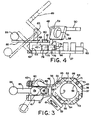
- the molds are supported by the fixture which is illustrated in more detail in Figures 3 and 4, and the fixture, with additional reference to such Figures, will be described initially.
- each bracket includes triangular upstanding corner posts seen at 68 and 69, and each is secured to the base plate by a fastener 70 extending through the reduced height center portion 71.
- the bracket 63 is provided with a set screw 72 seen in Figure 1 which is designed to clamp the mold 32 within the confines of brackets. It is noted that the brackets are arranged to provide a generally square enclosure for the generally square counter-mold 32, and that the flat edges of the mold each extend at about 45° to the pivot access or hinge 43.
- the strip passing diagonally between the clamp faces of the molds 31 and 32 clears the hinge area of the fixture.
- the elevated triangular posts not only confine the mold, but provide the edges of guide slots for the strip.
- the depressed center portions which provide clearance for the strip, but also enable an installer to remove and replace a counter-mold quite easily, even with a gloved hand.
- the inner end Is provided with a hook 88 adapted to swing beneath the head 81 of the locking stud 79 as seen in the full line positions of Figures 3 and 4.
- the locking stud head projects through the hole 47 when the upper pivoting support is in the shut or closed position seen in Figure 4. Moving the handle to the full line position seen will lock the fixture closed.
- the open position is shown in phantom lines at 89.
- the upper mold 31 which is also shown in detail in Figure 6 includes a cylindrical neck 90 which includes diametrically opposed recesses 91 and 92. These recesses accommodate the studs of shoulder bolts 93 seen in Figure 1 which are threaded in the diametrically opposed holes 53 and 54. In this manner the mold 31 is secured to the hinged portion of the fixture, and the bolts provide a slight gimbal pivot for the upper mold enabling it to adjust slightly to ensure that it is properly pressed against the counter-mold and any strip or other objects to be welded therebetween.
- the exothermic material When a weld is to be made, the exothermic material is inserted into the top of the crucible and into the crucible chamber on top of a metal disk which is seated at the bottom of the crucible chamber over the tap hole of the crucible. A starting powder may be inserted on top of the exothermic material.
- the exothermic material when ready to use, is then ignited by the igniter assembly seen at 112 in Figures 1 and 2.
- the igniter includes a cylindrical container 113 which has a bell-mouth bottom 115 designed to telescope over the top of the crucible.
- the igniter includes a removable lid 116 which may be attached to the chamber 113 by the chain 117.
- the lid includes a vent opening 118 directed away from the installer.
- Figure 5 illustrates a half or tap hole mold 125 which can be used by itself to make a weld connection such as seen in Figure 12.
- the mold 125 includes a tap hole 126 having at one end a crucible seat 127.
- the tap hole extends to an enlarged dome-like chamber 128 which opens to the bottom of the mold at the mold clamp face 129.
- the clamp face includes a laterally extending recess channel 130 designed to accommodate a strip 131 such as seen in Figure 12.
- the mold 125 may be used by itself secured in the hinged portion of the fixture, and clamped against a metal plate 132.
- the weld metal mass 133 is formed by the chamber 128.
- the connection seen in Figure 12 is known as a CG connection. If the metal plate 132 is relatively thin, it may be supported or backed up by a refractory block in the base of the fixture.
- Figure 6 illustrates the half mold 31 shown in the fixture 33.
- the lower rectangular portion 97 which includes the weld chamber 99 has aligned shallow recess channels 134 and 135 in the clamping face 136 on opposite sides of the chamber 99.
- Figure 9 illustrates a half mold 161 which generally corresponds to the mold 31 but which is adapted for vertical orientation connections.
- the mold 161 includes the diametrically opposed holes 162 and 163 to receive the fasteners 93 in the hinged support.
- the damping face 164 is provided with the weld recess 165 which is in communication with channels 166.
- the square upper portion on the mold is cut away as indicated at 167 to provide an inclined opening 168.
- the crucible may be supported on the inclined crucible support to direct the molten metal into the opening 167.
- the inclined crucible support may be mounted on either side as seen in comparing Figures 1 and 2.
- FIG 11 there is illustrated a counter-mold 178 which is somewhat thicker than the counter-mold seen in Figures 7 and 10.
- the counter-mold 178 has opposite clamping faces 179 and 180 in which are formed weld recesses 182 and 183, respectively.
- the shallow grooves 184 and 185 in such faces may be a different size enabling the counter-mold to be turned both 90° and to be flipped over face-to-face to form different types of strip or braid connections, for example.
- certain types of connections may be made with a single counter-mold, either horizontally or vertically, or aligned or crossing as seen in comparing the various connections made.
Landscapes
- Engineering & Computer Science (AREA)
- Mechanical Engineering (AREA)
- Molds, Cores, And Manufacturing Methods Thereof (AREA)
Description
Claims (15)
- Apparatus for welding flat objects such as electrical conductors in the form of strip, braid, bars, tape, and the like, said apparatus comprising one mold (31) and another mold (32), each having at least one clamping face (129; 136; 138; 150; 164; 179; 180), a channel (130; 34; 135; 140; 154; 166; 184; 185) in the clamping face of both of said molds, said channels being adapted to receive the objects to be welded together, means to clamp the molds together with weld objects (131; 132; 155; 156) in said channels, and means to introduce weld metal to the objects to weld them together, characterized in that, said apparatus includes a fixture (33; 37; 63 to 66) supporting one of said molds (31 or 32) for movement 90°C to orient its channel parallel to or transverse the channel of the other mold to form an aligned or transverse strip weld joint (142; 143; 144; 145; 170; 171; 172) with the introduction of the weld metal (133; 146; 157).
- Apparatus as set forth in claim 1, wherein one of said molds includes a tap hole (152) for introduction of weld metal to the mold (31, 32; 149; 161; 178).
- Apparatus as set forth in claim 1 or 2, wherein said fixture (37, 63 to 66) removably supports said one of said molds (31 or 32) for limited pivoting movement about a gimbal axis (43).
- Apparatus as set forth in one of claims 1 to 3, wherein said fixture (33; 37; 63 to 66) includes means removably supporting said one of said molds (31 or 32) for replacement with molds having a tap hole (152) oriented horizontally or vertically.
- Apparatus as forth in claim 4, wherein said fixture includes a crucible support (58; 153) for use when the fixture is in a vertical orientation.
- Apparatus as set forth in claim 4, wherein one of said molds (31) includes a crucible seat (90) for directly supporting a crucible (102) when said fixture (33; 37; 63 to 66) is in a horizontal orientation.
- Apparatus as set forth in one of claim 1 to 6 wherein said fixture (33) is a hinged two-part fixture, one part of said fixture being for each mold (31, 32).
- Apparatus as set forth in claim 5, wherein said crucible support (58; 153) is angled and mounted on one of sold fixture parts for supporting a crucible (102) when said fixture is in a vertical orientation.
- Apparatus as set forth in claim 6, wherein said one of said fixture parts supports said one of said molds (31) with a gimbal pivot (43), and said fixture includes an adjustable shut position to accommodate molds (31, 32) of different dimensions.
- Apparatus as set forth In one of claims 1 to 9, wherein said channels (130; 134; 135; 140; 154; 166; 184; 185) support said ship abutting each other when the molds (31; 32; 149; 161; 178) are closed.
- Method of welding strip (131; 155) comprising the steps of supporting one mold part (31 or 32) having a clamping face (129; 136; 138; 150; 164; 179; 180) with a strip recess channel (130; 134; 135; 140; 154; 166; 184; 185) therein, supporting a second mold part (32 or 31) also having a clamping face (129; 136; 138; 150; 164; 179; 180) with a strip recess channel (130; 134; 135; 140; 154; 166; 184; 185) therein, clamping the mold parts (31 and 32) together, and welding the strip, characterized by adjusting said second mold part with respect to said one mold part to form an aligned or transverse strip weld joint (142; 143; 144; 145; 170; 171; 172) wherein said second mold part is supported with respect to said one mold part for 90° adjustments around an axis normal to its clamping face.
- Method as set forth in claim 11, wherein molten metal is cast through a tap hole (95; 126; 152; 167) in said one maid part (31; 125; 149; 161) to form the weld (133; 146; 157).
- Method as set forth in claim 11 or 12, wherein the cast metal is formed exothermically.
- Method as set forth in claim 13, wherein the weld is formed vertically or horizontally and wherein said one mold part is substituted by another mold part having an appropriately oriented tap hole.
- Method as set forth in one of claims 11 to 14, wherein said one and said second mold part are supported in a hinged fixture (33), said one mold part being pivotally supported on a gimbal pivot (43) extending parallel to the clamping face.
Applications Claiming Priority (2)
| Application Number | Priority Date | Filing Date | Title |
|---|---|---|---|
| US4329697P | 1997-04-11 | 1997-04-11 | |
| US43296P | 1997-04-11 |
Publications (2)
| Publication Number | Publication Date |
|---|---|
| EP0870568A1 EP0870568A1 (en) | 1998-10-14 |
| EP0870568B1 true EP0870568B1 (en) | 2003-07-02 |
Family
ID=21926448
Family Applications (1)
| Application Number | Title | Priority Date | Filing Date |
|---|---|---|---|
| EP98106702A Expired - Lifetime EP0870568B1 (en) | 1997-04-11 | 1998-04-14 | Strip welder and method |
Country Status (2)
| Country | Link |
|---|---|
| EP (1) | EP0870568B1 (en) |
| DE (1) | DE69815918T2 (en) |
Families Citing this family (6)
| Publication number | Priority date | Publication date | Assignee | Title |
|---|---|---|---|---|
| US6382496B1 (en) * | 2000-07-27 | 2002-05-07 | Harger, Inc. | Welding handle clamp |
| CN103894730A (en) * | 2014-03-20 | 2014-07-02 | 南京唐模电气科技有限公司 | Module combined type heat-released welding mould |
| CN107030373A (en) * | 2017-06-09 | 2017-08-11 | 秉岳电气(上海)有限公司 | One kind is used to put heat weldable novel die and welding method |
| WO2019040309A1 (en) | 2017-08-21 | 2019-02-28 | Hubbell Incorporated | Handle for exothermic mold with spring connectors |
| US10738999B2 (en) | 2017-10-03 | 2020-08-11 | Hubbell Incorporated | Trigger devices for exothermix welds |
| WO2019178405A1 (en) * | 2018-03-14 | 2019-09-19 | Erico International Corporation | Modular welding mold |
Family Cites Families (3)
| Publication number | Priority date | Publication date | Assignee | Title |
|---|---|---|---|---|
| DE1169763B (en) * | 1961-07-31 | 1964-05-06 | Erico Prod Inc | Device for exothermic welding |
| DE1201156B (en) * | 1963-10-08 | 1965-09-16 | Elektro Thermit Gmbh | Mold for aluminothermic rail welding |
| FR2679807B1 (en) * | 1991-08-02 | 1995-09-29 | Erico France Sarl | PROCESS FOR IN SITU BRAZING A METAL ELEMENT ON A METAL SUPPORT AND DEVICE FOR ITS IMPLEMENTATION. |
-
1998
- 1998-04-14 EP EP98106702A patent/EP0870568B1/en not_active Expired - Lifetime
- 1998-04-14 DE DE69815918T patent/DE69815918T2/en not_active Expired - Fee Related
Also Published As
| Publication number | Publication date |
|---|---|
| EP0870568A1 (en) | 1998-10-14 |
| DE69815918T2 (en) | 2004-06-03 |
| DE69815918D1 (en) | 2003-08-07 |
Similar Documents
| Publication | Publication Date | Title |
|---|---|---|
| EP1273381B1 (en) | Welding apparatus and method for forming electrical connections | |
| US5954261A (en) | Welding mold and method | |
| US5715886A (en) | Single use welding mold and method | |
| US4119137A (en) | Automated post burn station | |
| US6382496B1 (en) | Welding handle clamp | |
| US5533662A (en) | Exothermic welding apparatus | |
| US5653279A (en) | Apparatus and method for forming electrical connections | |
| EP0870568A1 (en) | Strip welder and method | |
| US5829510A (en) | Exothermic welding crucible and method | |
| JP3215868B2 (en) | Immersion nozzle replacement device | |
| US20190001431A1 (en) | Configurable exothermic reaction mold | |
| CA1088175A (en) | Cable lug and method of making same | |
| JP2002028792A (en) | Improvements in heat welding | |
| US5279455A (en) | Method of attaching a metal element to a metal supporting surface by brazing and apparatus for its implementation | |
| US3980126A (en) | Automated post burn station | |
| US4050501A (en) | Method of fusing a metal battery terminal post with a metal bushing | |
| US3554270A (en) | Metal casing apparatus and method | |
| EP0870569B1 (en) | Welding apparatus and method | |
| US2401048A (en) | Rail bonding apparatus | |
| US4458742A (en) | Method for thermal relay welding | |
| US4399860A (en) | Apparatus for strip casting | |
| JPH06505921A (en) | Sliding closure device for molten metal containers | |
| JP2004106055A (en) | Forging die for half-melted metal and forming method using such die | |
| US3954216A (en) | Apparatus for thermal relay welding | |
| JPH0622748B2 (en) | Molten metal pouring method and sliding gate valve |
Legal Events
| Date | Code | Title | Description |
|---|---|---|---|
| PUAI | Public reference made under article 153(3) epc to a published international application that has entered the european phase |
Free format text: ORIGINAL CODE: 0009012 |
|
| AK | Designated contracting states |
Kind code of ref document: A1 Designated state(s): DE ES FR GB IT NL |
|
| AX | Request for extension of the european patent |
Free format text: AL;LT;LV;MK;RO;SI |
|
| 17P | Request for examination filed |
Effective date: 19990318 |
|
| AKX | Designation fees paid |
Free format text: DE ES FR GB IT NL |
|
| 17Q | First examination report despatched |
Effective date: 20020712 |
|
| GRAH | Despatch of communication of intention to grant a patent |
Free format text: ORIGINAL CODE: EPIDOS IGRA |
|
| GRAH | Despatch of communication of intention to grant a patent |
Free format text: ORIGINAL CODE: EPIDOS IGRA |
|
| GRAA | (expected) grant |
Free format text: ORIGINAL CODE: 0009210 |
|
| AK | Designated contracting states |
Designated state(s): DE ES FR GB IT NL |
|
| PG25 | Lapsed in a contracting state [announced via postgrant information from national office to epo] |
Ref country code: IT Free format text: LAPSE BECAUSE OF FAILURE TO SUBMIT A TRANSLATION OF THE DESCRIPTION OR TO PAY THE FEE WITHIN THE PRESCRIBED TIME-LIMIT;WARNING: LAPSES OF ITALIAN PATENTS WITH EFFECTIVE DATE BEFORE 2007 MAY HAVE OCCURRED AT ANY TIME BEFORE 2007. THE CORRECT EFFECTIVE DATE MAY BE DIFFERENT FROM THE ONE RECORDED. Effective date: 20030702 Ref country code: ES Free format text: LAPSE BECAUSE OF FAILURE TO SUBMIT A TRANSLATION OF THE DESCRIPTION OR TO PAY THE FEE WITHIN THE PRESCRIBED TIME-LIMIT Effective date: 20030702 |
|
| REG | Reference to a national code |
Ref country code: GB Ref legal event code: FG4D |
|
| REF | Corresponds to: |
Ref document number: 69815918 Country of ref document: DE Date of ref document: 20030807 Kind code of ref document: P |
|
| ET | Fr: translation filed | ||
| PLBE | No opposition filed within time limit |
Free format text: ORIGINAL CODE: 0009261 |
|
| STAA | Information on the status of an ep patent application or granted ep patent |
Free format text: STATUS: NO OPPOSITION FILED WITHIN TIME LIMIT |
|
| 26N | No opposition filed |
Effective date: 20040405 |
|
| PGFP | Annual fee paid to national office [announced via postgrant information from national office to epo] |
Ref country code: FR Payment date: 20060313 Year of fee payment: 9 |
|
| PGFP | Annual fee paid to national office [announced via postgrant information from national office to epo] |
Ref country code: NL Payment date: 20060315 Year of fee payment: 9 |
|
| PGFP | Annual fee paid to national office [announced via postgrant information from national office to epo] |
Ref country code: DE Payment date: 20060317 Year of fee payment: 9 |
|
| GBPC | Gb: european patent ceased through non-payment of renewal fee |
Effective date: 20070414 |
|
| NLV4 | Nl: lapsed or anulled due to non-payment of the annual fee |
Effective date: 20071101 |
|
| PG25 | Lapsed in a contracting state [announced via postgrant information from national office to epo] |
Ref country code: NL Free format text: LAPSE BECAUSE OF NON-PAYMENT OF DUE FEES Effective date: 20071101 Ref country code: DE Free format text: LAPSE BECAUSE OF NON-PAYMENT OF DUE FEES Effective date: 20071101 |
|
| PG25 | Lapsed in a contracting state [announced via postgrant information from national office to epo] |
Ref country code: GB Free format text: LAPSE BECAUSE OF NON-PAYMENT OF DUE FEES Effective date: 20070414 |
|
| PG25 | Lapsed in a contracting state [announced via postgrant information from national office to epo] |
Ref country code: FR Free format text: LAPSE BECAUSE OF NON-PAYMENT OF DUE FEES Effective date: 20070430 |
|
| PGFP | Annual fee paid to national office [announced via postgrant information from national office to epo] |
Ref country code: GB Payment date: 20060316 Year of fee payment: 9 |