EP0870136B1 - Circumferential seal with ceramic rotor - Google Patents
Circumferential seal with ceramic rotor Download PDFInfo
- Publication number
- EP0870136B1 EP0870136B1 EP97903782A EP97903782A EP0870136B1 EP 0870136 B1 EP0870136 B1 EP 0870136B1 EP 97903782 A EP97903782 A EP 97903782A EP 97903782 A EP97903782 A EP 97903782A EP 0870136 B1 EP0870136 B1 EP 0870136B1
- Authority
- EP
- European Patent Office
- Prior art keywords
- engine
- shaft
- clamping member
- seal
- axially
- Prior art date
- Legal status (The legal status is an assumption and is not a legal conclusion. Google has not performed a legal analysis and makes no representation as to the accuracy of the status listed.)
- Expired - Lifetime
Links
Images

Classifications
-
- F—MECHANICAL ENGINEERING; LIGHTING; HEATING; WEAPONS; BLASTING
- F16—ENGINEERING ELEMENTS AND UNITS; GENERAL MEASURES FOR PRODUCING AND MAINTAINING EFFECTIVE FUNCTIONING OF MACHINES OR INSTALLATIONS; THERMAL INSULATION IN GENERAL
- F16C—SHAFTS; FLEXIBLE SHAFTS; ELEMENTS OR CRANKSHAFT MECHANISMS; ROTARY BODIES OTHER THAN GEARING ELEMENTS; BEARINGS
- F16C33/00—Parts of bearings; Special methods for making bearings or parts thereof
- F16C33/72—Sealings
- F16C33/76—Sealings of ball or roller bearings
-
- F—MECHANICAL ENGINEERING; LIGHTING; HEATING; WEAPONS; BLASTING
- F01—MACHINES OR ENGINES IN GENERAL; ENGINE PLANTS IN GENERAL; STEAM ENGINES
- F01D—NON-POSITIVE DISPLACEMENT MACHINES OR ENGINES, e.g. STEAM TURBINES
- F01D11/00—Preventing or minimising internal leakage of working-fluid, e.g. between stages
- F01D11/003—Preventing or minimising internal leakage of working-fluid, e.g. between stages by packing rings; Mechanical seals
-
- F—MECHANICAL ENGINEERING; LIGHTING; HEATING; WEAPONS; BLASTING
- F16—ENGINEERING ELEMENTS AND UNITS; GENERAL MEASURES FOR PRODUCING AND MAINTAINING EFFECTIVE FUNCTIONING OF MACHINES OR INSTALLATIONS; THERMAL INSULATION IN GENERAL
- F16J—PISTONS; CYLINDERS; SEALINGS
- F16J15/00—Sealings
- F16J15/54—Other sealings for rotating shafts
-
- F—MECHANICAL ENGINEERING; LIGHTING; HEATING; WEAPONS; BLASTING
- F16—ENGINEERING ELEMENTS AND UNITS; GENERAL MEASURES FOR PRODUCING AND MAINTAINING EFFECTIVE FUNCTIONING OF MACHINES OR INSTALLATIONS; THERMAL INSULATION IN GENERAL
- F16C—SHAFTS; FLEXIBLE SHAFTS; ELEMENTS OR CRANKSHAFT MECHANISMS; ROTARY BODIES OTHER THAN GEARING ELEMENTS; BEARINGS
- F16C2360/00—Engines or pumps
- F16C2360/23—Gas turbine engines
Definitions
- the present invention relates generally to circumferential seals used for sealing along rotating shafts, and in particular, to a circumferential seal having a ceramic seal rotor flexibly mounted to a rotating shaft.
- Circumferential seals are used, for example, in gas turbine engines to prevent leakage of fluid along the engine's rotating shaft where the shaft extends through a wall or partition.
- a typical circumferential seal includes a rotating component called a seal rotor 20 and a non-rotating component called a seal stator 31.
- the rotor 20 is made of metal and is mounted to a rotating shaft 12. It also has a radially, outward facing sealing surface 21.
- the seal stator 31 includes a metal ring 35 mounted to the housing 34 and a carbon sealing ring 36 mounted to its radial inward facing surface.
- the stator 31 and rotor 20 are arranged so that the carbon ring 36 circumscribes the sealing surface 21 so as to seal a leakage path represented by arrow 38. To avoid damage to the carbon ring 36, a small radial gap is maintained between the ring 36 and sealing surface 21.
- a common problem associated with these seals occurs as a result of variation in the radial gap between the carbon ring 36 and sealing surface 21.
- This variation is due in part to the mechanical growth of the rotor 20 due to centrifugal effects, but more significantly due to a disparity in thermal growth between the metal rotor and the carbon ring in response to changes in temperature. This disparity results from the two components having different coefficients of thermal expansion.
- the variation in the radial gap produces undesirable effects either when the radial gap is too wide open, or if it is allowed to completely close.
- the gap becomes too large, the amount of leakage through the seal increases resulting in reduced efficiency.
- the increased flow can adversely affect the control of pressures in neighboring cavities and hamper the intended use of the high-pressure air therein.
- substantial contact between the carbon ring and rotor can occur which can quickly damage either or both components.
- One proposal for improving seal performance is to make the seal rotor from titanium, which has one of the lowest thermal expansion coefficients of any metal, and additionally satisfies strength requirements for a seal rotor.
- the differential thermal growth between a titanium rotor and carbon ring is substantially less than that of a seal with a more conventional nickel or iron based alloy rotor, however, it is not reduced enough to significantly improve seal performance. This is primarily due to the fact that although the thermal expansion coefficient of titanium is low for a metal, it is still much higher than that of carbon. Further, the titanium is substantially less durable than conventional rotor alloys, and thus more susceptible to damage upon contact with the stator.
- a seal rotor can be cooled by providing a flow of cooling oil over its inside surfaces. This has the beneficial effect of reducing the rotor's temperature, and correspondingly reducing its thermal growth. By actively controlling the rotor's thermal growth in this way, the differential growth between the stator and rotor can be minimized.
- One disadvantage to an active cooling system is the added design complexity required for providing the means to deliver the oil to the runner, and the additional costs associated with that complexity.
- Another disadvantage is an increased risk of contamination of the air side of the seal due to the additional supply of oil in close proximity to the seal interface.
- US-A-5183270 discloses a rotor shaft with carbon ring seal.
- An object of the invention is to provide a circumferential seal in which engagement between the carbon ring and the rotor remains substantially constant in the presence of varying temperature.
- the present invention achieves the above-stated object by providing a gas turbine engine assembled in a lockup and comprising a circumferential seal sealing between an axially extending rotating shaft and a housing circumscribing the shaft, the seal comprising:
- the thermal and mechanical growth characteristics of the ceramic sealing member are substantially similar to the thermal growth of the carbon seal portion.
- the ceramic sealing member is able to maintain rubbing contact with the carbon portion despite varying temperature.
- the clamping means isolates the ceramic sealing member from the compressive force of the lockup assembly, thereby avoiding damage to the ceramic sealing member.
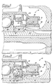
- FIG. 2 shows a section of a gas turbine engine generally denoted by the reference numeral 10.
- the section 10 includes a rotating shaft 12 on which rotating engine components, such as the radial compressor wheel 16, are mounted.
- Circumscribing the shaft 12 is a stationary housing 34.
- the housing 34 is mounted atop a bearing 30 having an inner race 32 which is mounted on the shaft 12.
- Disposed between the housing 34 and shaft 12 is a circumferential seal 29.
- the seal 29 includes a conventional stator 31 having a metal ring 35 mounted to the housing 34 and a carbon sealing ring 36 mounted to its radial inward facing surface. Alternatively, the carbon portion may be embedded in the ring 35.
- the seal 29 also includes a novel sealing rotor 49.
- the rotor 49 includes a ceramic, preferably silicon nitride, cylindrical member 50 having a radially outward facing sealing surface 51 in rubbing contact with the carbon ring 36 to control leakage air flow represented by arrow 38.
- the member 50 has radially outward extending flange 53 which acts as an oil slinger preventing oil flowing through the bearing 30 from reaching the sealing surface 51.
- the member 50 has a radially inward extending mounting flange 70 having axial faces adapted to receive an axial clamping load.
- the rotor 49 further includes two metallic, annular clamping members 52, and 54 for providing this clamping load.
- Clamping member 52 includes a portion 56 having a radially inwardly extending flange 58 at one end, and a radially outwardly extending lip 60 at the other end.
- the length and thickness of the portion 56 are selected to impart radial flexibility to the clamping member 52. That is the portion 56 acts as a cantilevered beam rigidly fixed at the flange 58. To achieve the desired radial flexibility the ratio of thickness-to-length for the portion 56 should preferably be less than one fifth.
- Clamping member 54 has a cylindrical portion 62 having a radially inward extending flange 64 at one end, and an axial face 66 at the other end. As shown in FIG. 4, the cylindrical portion 62 has a plurality of circumferentially extending slots 74 that extend through the portion 62. The slots 74 impart axial flexibility to the portion allowing it to compress and expand like a coil spring in a mattress. Though not essential, at the circumferential end of each slot 74 is a hole 76 having a diameter about twice the width of the slot. The holes 76 act to relieve stress concentration when the portion 56 is axially loaded.
- a spacer 26 is placed over the shaft 12 such that it axially abuts the shoulder 14.
- Clamping member 52 is then slid over the spacer 26 until the flange 58 contacts the spacer 26.
- the ceramic member 50 is then installed over the shaft 12 and member 52 so that one of the axial faces of flange 70 contacts the lip 60.
- the portion 56 of clamping member 52 is tapered such that as member 50 nears the lip 60 a radial interference is encountered, resulting in a slight radial press fit when fully installed.
- the slight radial press ensures accurate radial positioning of the ceramic member 50.
- the taper should be no more than fifteen degrees from the axial direction.
- Clamping member 54 is installed next by sliding it over shaft 12 and member 52, until its axial face 66 abuts the other axial face of flange 70.
- the dimensions of member 54 are selected such that an axial gap is formed between flange 64 and flange 58.
- the bearing 30 and other rotating components are then mounted onto the shaft 12.
- the last item to be mounted on the shaft 12 is a nut, not shown, that is torqued down thereby generating an axial compressive force, represented by arrow F of about 13600 kg ( 30,000 lbs).
- This force is transmitted to the other components mounted on shaft 12 and in particular through the inner race 32, then flange 64, then flange 58, then spacer 26, and then taken out against shoulder 14.
- the inner race 32, flange 64, flange 58, and spacer 26 become a compressed stack much the same as a stack of washers placed over a bolt become compressed against the bolt head by tightening a nut down onto the stack.
- This stacking of components under load is referred to as a lockup assembly.
- the circumferential seal 29 provides substantially improved sealing efficiency over the prior art by virtue of the ceramic member 50.
- the thermal growth of the ceramic is low due to its low coefficient of thermal expansion.
- the mechanical radial growth due to centrifugal forces is also low due to the high stiffness-to-weight ratio of the ceramic.
- the ceramic member 50 is able to closely track the carbon portion 36 resulting in a more constant gap therebetween throughout the entire operating envelope of the engine 10.
- the frictional and wear properties of the ceramic-to-carbon interface are substantially improved over the prior art, thus allowing the sealing surface 51 to be in rubbing contact with the carbon portion 36, rather than the intermittent rubbing contact of the prior art.
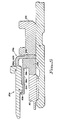
- a ceramic member 50a is clamped between two metallic clamping members 52a and 54a.
- Ceramic member 50a includes axial faces 71 and 72 as shown, adapted to receive an axial clamping load.
- Radially flexible member 52a has a thin portion 56a having a radially outward extending lip 60a for clamping to face 71 at one end, and a radially inward extending flange portion 58a for mounting to a rotating shaft 12 at the other end.
- Flange portion 58a incorporates an integral spacer portion 26a for axially positioning the components.
- Axially flexible member 54a has a cylindrical portion 62a having circumferentially extending slots (not shown) for providing axial flexibility; a flange portion 64a extending radially inward from one end for mounting to shaft 12; and a surface 66a at the other end for applying the axial clamp load to face 72.
- a lockup assembly is created by torquing down a nut 80, thereby axially loading spacer portion 26a, flange portion 64a, bearing inner race 32a, and one or more additional rotating components not shown, against a shoulder (not shown) of shaft 12.
- the lockup assembly causes ceramic member 50a to be flexibly clamped between lip 60a and face 66a in the same manner as described above for the preferred embodiment.
Landscapes
- Engineering & Computer Science (AREA)
- General Engineering & Computer Science (AREA)
- Mechanical Engineering (AREA)
- Mechanical Sealing (AREA)
- Turbine Rotor Nozzle Sealing (AREA)
- Gasket Seals (AREA)
- Sealing Devices (AREA)
Description
Claims (10)
- A gas turbine engine (10) assembled in a lockup and comprising a circumferential seal (24) sealing between an axially extending rotating shaft (12) and a housing (34) circumscribing the shaft, the seal comprising:a seal stator (31) mounted to the housing and having a radially inward facing carbon portion (36); and characterised bya seal rotor (49) having a metal clamping member (52, 54) mounted to the shaft (12), and a ceramic sealing member (50) mounted to the metal clamping member and having a radially outward facing surface (51) in rubbing contact with the carbon portion.
- An engine (10) according to claim 1, wherein the ceramic sealing member (50) has first and second axially facing mounting surfaces.
- An engine (10) according to claim 2, wherein the metal clamping member (52, 54) is held on the shaft (12) by a compressive force generated by a lockup assembly.
- An engine (10) according to claim 3, wherein the metal clamping member comprises:a first annular (54) axially flexible, clamping member mounted to the shaft (12) and having a first axially facing surface in contact with the first mounting surface; anda second annular (52); radially flexible, clamping member mounted to the shaft and having a second axially facing surface in contact with the second mounting surface, whereby upon the application of the compressive force to the first and second clamping members, the first clamping member is placed in compression and the second clamping member is placed in tension thereby clamping onto the ceramic sealing member (50).
- An engine (10) according to claim 4, wherein the first and second clamping members are adjacent.
- An engine (10) according to claim 4, wherein the first clamping member (54) comprises: a first annular flange (64) having a first hole for receiving the shaft (12); and
a first cylindrical member (62) extending axially from the radial outer end of the first annular flange and terminating at the first axially facing surface in contact with the first mounting surface. - An engine (10) according to claim 6, wherein the first cylindrical member (62), has a plurality of circumferentially extending slots (74).
- An engine (10) according to claim 7, wherein each of the slots (74) terminates at a stress relief hole (76).
- An engine (10) according to claim 8, wherein the stress relief holes (76) have a diameter about twice the width of the slots (74).
- An engine (10) according to claim 4, wherein the second clamping member (52) comprises:a second annular flange (58) having a second hole for receiving the shaft (12); anda second member (56) extending axially from the radial outer end of the annular flange to a radially outward extending lip (66), the lip defining the second axially facing surface in contact with the second mounting surface.
Applications Claiming Priority (3)
| Application Number | Priority Date | Filing Date | Title |
|---|---|---|---|
| US588825 | 1990-09-27 | ||
| US58882596A | 1996-01-19 | 1996-01-19 | |
| PCT/US1997/000449 WO1997026475A1 (en) | 1996-01-19 | 1997-01-16 | Circumferential seal with ceramic rotor |
Publications (2)
| Publication Number | Publication Date |
|---|---|
| EP0870136A1 EP0870136A1 (en) | 1998-10-14 |
| EP0870136B1 true EP0870136B1 (en) | 2002-09-04 |
Family
ID=24355451
Family Applications (1)
| Application Number | Title | Priority Date | Filing Date |
|---|---|---|---|
| EP97903782A Expired - Lifetime EP0870136B1 (en) | 1996-01-19 | 1997-01-16 | Circumferential seal with ceramic rotor |
Country Status (8)
| Country | Link |
|---|---|
| US (1) | US6322081B1 (en) |
| EP (1) | EP0870136B1 (en) |
| JP (1) | JP2000503373A (en) |
| AU (1) | AU1826397A (en) |
| CA (1) | CA2239460C (en) |
| DE (1) | DE69715147T2 (en) |
| ES (1) | ES2179296T3 (en) |
| WO (1) | WO1997026475A1 (en) |
Families Citing this family (35)
| Publication number | Priority date | Publication date | Assignee | Title |
|---|---|---|---|---|
| US6655695B1 (en) * | 2001-02-13 | 2003-12-02 | Honeywell International Inc. | Face seal assembly with composite rotor |
| JP4530132B2 (en) * | 2004-01-22 | 2010-08-25 | 株式会社ジェイテクト | Electric pump |
| US20060062499A1 (en) * | 2004-04-08 | 2006-03-23 | Boyd Gary L | Integrated hydrodynamic air bearing and seal |
| US20060033287A1 (en) * | 2004-08-11 | 2006-02-16 | Giuseppe Rago | Controlled gap carbon seal |
| US7905495B2 (en) * | 2007-11-29 | 2011-03-15 | Rolls-Royce Corporation | Circumferential sealing arrangement |
| US8167314B2 (en) * | 2009-03-31 | 2012-05-01 | United Technologies Corporation | Distortion resistant face seal counterface system |
| GB2473828B (en) | 2009-09-24 | 2011-08-10 | Rolls Royce Plc | Oil seal assembly |
| JP5174069B2 (en) * | 2010-03-15 | 2013-04-03 | 本田技研工業株式会社 | Centrifugal compressor |
| US8657573B2 (en) | 2010-04-13 | 2014-02-25 | Rolls-Royce Corporation | Circumferential sealing arrangement |
| US9359912B2 (en) * | 2011-01-10 | 2016-06-07 | United Technologies Corporation | Runner for circumferential seals |
| US8932011B2 (en) | 2011-10-06 | 2015-01-13 | United Technologies Corporation | Shaft assembly for a gas turbine engine |
| CA2860276C (en) * | 2011-12-22 | 2018-06-12 | Eaton Corporation | Coning resistant rotor for a seal assembly |
| US10233762B2 (en) | 2013-02-27 | 2019-03-19 | United Technologies Corporation | Cooled seal assembly for arranging between a stator and a rotor |
| US10260364B2 (en) | 2015-03-09 | 2019-04-16 | United Technologies Corporation | Sliding seal |
| ES2865277T3 (en) | 2015-03-31 | 2021-10-15 | Saint Gobain Performance Plastics Pampus Gmbh | Bearing with shoulder segments |
| US10202862B2 (en) * | 2015-04-08 | 2019-02-12 | United Technologies Corporation | Sliding seal |
| US10753219B2 (en) | 2015-05-26 | 2020-08-25 | Pratt & Whitney Canada Corp. | Internally cooled seal runner and method of cooling seal runner of a gas turbine engine |
| US10571028B2 (en) * | 2016-02-16 | 2020-02-25 | Rolls-Royce Corporation | Ceramic seal runner support system |
| US10174845B2 (en) | 2016-02-16 | 2019-01-08 | Rolls-Royce Corporation | Ceramic seal runner and mount for a rotating shaft |
| EP3267079B1 (en) * | 2016-07-08 | 2022-06-22 | Goodrich Actuation Systems Limited | Rotary sealing arrangement |
| US11193591B2 (en) * | 2017-08-03 | 2021-12-07 | Raytheon Technologies Corporation | Seal sacrificial wear indicator |
| US10598020B2 (en) * | 2018-01-05 | 2020-03-24 | United Technologies Corporation | Spanner nut centering feature |
| US11054039B2 (en) * | 2018-08-31 | 2021-07-06 | Rolls-Royce Corporation | Seal runner support |
| US11255436B2 (en) | 2018-11-30 | 2022-02-22 | Rolls-Royce Corporation | Circumferential archbound carbon seal on ceramic runner |
| US11193590B2 (en) | 2019-01-14 | 2021-12-07 | Rolls-Royce Corporation | Seal assembly with buffered lip seal |
| US10927960B2 (en) * | 2019-02-01 | 2021-02-23 | Rolls-Royce Corporation | Mounting assembly for a ceramic seal runner |
| US10935142B2 (en) * | 2019-02-01 | 2021-03-02 | Rolls-Royce Corporation | Mounting assembly for a ceramic seal runner |
| US20200248814A1 (en) * | 2019-02-01 | 2020-08-06 | Rolls-Royce Corporation | Seal assembly with spring retainer runner mount assembly |
| US11286990B2 (en) * | 2019-04-03 | 2022-03-29 | Raytheon Technologies Corporation | Seal runner with deflector and catcher for gas turbine engine |
| US11499442B2 (en) | 2019-04-12 | 2022-11-15 | Raytheon Technologies Corporation | Bearing compartment seal configuration for a gas turbine engine |
| US11415225B2 (en) | 2019-05-22 | 2022-08-16 | Rolls-Royce Corporation | Seal assembly with deflecting runner mount assembly |
| US11339675B2 (en) * | 2019-09-13 | 2022-05-24 | Raytheon Technologies Corporation | Seal seat insert for gas turbine engines |
| US11655721B2 (en) * | 2020-10-29 | 2023-05-23 | Borgwarner Inc. | Turbocharger including a sealing assembly |
| US11466584B1 (en) | 2021-07-29 | 2022-10-11 | Rolls-Royce Corporation | Ceramic runner seal assembly with compliant holder |
| US12163433B2 (en) * | 2023-03-23 | 2024-12-10 | Pratt & Whitney Canada Corp. | Runner clearance optimization using tailored material density |
Family Cites Families (33)
| Publication number | Priority date | Publication date | Assignee | Title |
|---|---|---|---|---|
| US2937039A (en) | 1957-05-29 | 1960-05-17 | Chicago Rawhide Mfg Co | Controlled gap seal |
| US3285614A (en) * | 1963-08-13 | 1966-11-15 | Beloit Corp | Intermediate shaft pneumatic seal |
| US3502343A (en) * | 1968-03-04 | 1970-03-24 | Avco Corp | Slipping cone seal |
| US3822066A (en) * | 1969-03-07 | 1974-07-02 | Caterpillar Tractor Co | Seal |
| US3652183A (en) | 1970-10-15 | 1972-03-28 | John E Pottharst Jr | Compressor |
| SE347334B (en) | 1970-12-30 | 1972-07-31 | Stenberg Flygt Ab | |
| US3797899A (en) * | 1971-09-27 | 1974-03-19 | Trw Inc | Multiple lip outer land riding seal |
| US3907308A (en) * | 1973-09-27 | 1975-09-23 | Westinghouse Electric Corp | Bell seal vibration damper and seal improvement |
| US4036505A (en) | 1973-12-06 | 1977-07-19 | The Wickes Corporation | Mechanical seals |
| US3926443A (en) | 1974-03-05 | 1975-12-16 | Coors Porcelain Co | Composite seal ring and assembly |
| US3895811A (en) * | 1974-07-19 | 1975-07-22 | Gen Motors Corp | Face sealing arrangement for automotive waterpumps and the like and face seal assembly therefor |
| US4174844A (en) | 1975-12-05 | 1979-11-20 | Crane Packing Company | Mechanical seal |
| JPS54160954A (en) | 1978-06-12 | 1979-12-20 | Arai Pump Mfg | Seal ring |
| JPS551447A (en) | 1978-06-21 | 1980-01-08 | Arai Pump Mfg Co Ltd | Seal ring for multiple end surface |
| CH633350A5 (en) * | 1978-10-26 | 1982-11-30 | Sulzer Ag | ARRANGEMENT FOR SEALING THE JOINT BETWEEN TWO STATOR PARTS OF A TURBO MACHINE, IN PARTICULAR A GAS TURBINE. |
| US4196912A (en) | 1978-11-24 | 1980-04-08 | Amax Inc. | Fluid-pressurized face seal |
| US4323255A (en) | 1979-08-13 | 1982-04-06 | Borg-Warner Corporation | Mechanical seal with eccentric seal faces |
| US4336944A (en) | 1979-08-27 | 1982-06-29 | Raybestos-Manhattan, Inc. | Mechanical-dynamic rotary seal |
| US4515377A (en) * | 1982-08-06 | 1985-05-07 | Johnson Leslie V | Rotary seal assembly having a liquid filled bellows |
| US4415165A (en) | 1982-12-02 | 1983-11-15 | The United States Of America As Represented By The Secretary Of The Navy | Integral elastomeric/graphite dynamic face seal |
| US4484752A (en) * | 1984-03-08 | 1984-11-27 | Federal-Mogul Corporation | Rotating-lip bidirectional hydrodynamic oil seal |
| GB8412875D0 (en) * | 1984-05-19 | 1984-06-27 | Flexibox Ltd | Mechanical seals |
| DE3671279D1 (en) | 1985-11-01 | 1990-06-21 | Crane John Uk Ltd | MECHANICAL SEALS. |
| US4836559A (en) * | 1987-12-30 | 1989-06-06 | Sundstrand Corporation | Seal assembly with meltable metal binder layer |
| DE3828833A1 (en) * | 1988-08-25 | 1990-03-01 | Mtu Muenchen Gmbh | DEVICE FOR SEALING MEDIA, LIQUIDS AND / OR GASES, DIFFERENT PRESSURES, ROOMS IN PARTICULAR, IN PARTICULAR FOR TURBO MACHINES |
| US5017022A (en) | 1988-11-09 | 1991-05-21 | Allied-Signal, Inc. | High temperature bearing |
| US5014999A (en) * | 1989-03-06 | 1991-05-14 | Car-Graph, Inc. | Pressure enhanced self aligning seal |
| GB2231105B (en) | 1989-04-24 | 1993-04-14 | Sealol | Drained face seal |
| CH680606A5 (en) * | 1989-07-12 | 1992-09-30 | Escher Wyss Ag | |
| US4973065A (en) | 1989-10-20 | 1990-11-27 | A. W. Chesterton Company | Seal assembly |
| US5263724A (en) * | 1989-11-02 | 1993-11-23 | Volund Miljoteknik A/S | Segmented seal for rotary equipment |
| US5183270A (en) * | 1991-09-16 | 1993-02-02 | Allied-Signal Inc. | Composite seal rotor |
| DE4229081C1 (en) * | 1992-05-27 | 1993-12-23 | Escher Wyss Ag | Dry gas seal |
-
1997
- 1997-01-16 EP EP97903782A patent/EP0870136B1/en not_active Expired - Lifetime
- 1997-01-16 DE DE69715147T patent/DE69715147T2/en not_active Expired - Fee Related
- 1997-01-16 CA CA002239460A patent/CA2239460C/en not_active Expired - Fee Related
- 1997-01-16 WO PCT/US1997/000449 patent/WO1997026475A1/en not_active Ceased
- 1997-01-16 JP JP9526092A patent/JP2000503373A/en active Pending
- 1997-01-16 ES ES97903782T patent/ES2179296T3/en not_active Expired - Lifetime
- 1997-02-16 AU AU18263/97A patent/AU1826397A/en not_active Abandoned
- 1997-07-11 US US08/903,185 patent/US6322081B1/en not_active Expired - Fee Related
Also Published As
| Publication number | Publication date |
|---|---|
| CA2239460A1 (en) | 1997-07-24 |
| DE69715147T2 (en) | 2003-01-09 |
| EP0870136A1 (en) | 1998-10-14 |
| DE69715147D1 (en) | 2002-10-10 |
| WO1997026475A1 (en) | 1997-07-24 |
| ES2179296T3 (en) | 2003-01-16 |
| AU1826397A (en) | 1997-08-11 |
| JP2000503373A (en) | 2000-03-21 |
| US6322081B1 (en) | 2001-11-27 |
| CA2239460C (en) | 2005-09-06 |
Similar Documents
| Publication | Publication Date | Title |
|---|---|---|
| US6322081B1 (en) | Circumferential seal with ceramic rotor | |
| US5984316A (en) | Rotary reciprocating seals with internal metal band | |
| EP3938668B1 (en) | Foil bearing assembly and compressor including same | |
| US5626347A (en) | Coning resistant face seal having a "U" shape | |
| JP3934850B2 (en) | Face seal structure | |
| CN102667199B (en) | Turbocharger with a case | |
| US8167494B2 (en) | Squeeze-film damper arrangement | |
| US7018104B2 (en) | Bearing assembly and method | |
| US20100132186A1 (en) | Method of assembling a pump motor with bearing preload | |
| US5639096A (en) | Oil film cooled face seal | |
| US5183270A (en) | Composite seal rotor | |
| EP2381145B1 (en) | Distortion resistant face seal counterface system | |
| JP4762737B2 (en) | Turbomachines, especially turbochargers | |
| JP2000179357A (en) | Seal assembly for inter-shaft seal of gas turbine engine | |
| US11396947B2 (en) | Face seal with welded bellows | |
| US5160149A (en) | Seal rotor mount | |
| US6322079B1 (en) | Face seal | |
| US5558343A (en) | Water pump seal assembly | |
| GB2076480A (en) | Shaft | |
| US4854598A (en) | Slide ring seal with carrier body | |
| US3485538A (en) | Journal mounting for rotatable shaft | |
| EP0549751A1 (en) | THERMALLY COMPENSATED PRE-LOADED ASSEMBLY. | |
| JP2002122243A (en) | Split type seal | |
| JP4469637B2 (en) | Exhaust control device for internal combustion engine | |
| US4384727A (en) | Circumferential ring seal assembly |
Legal Events
| Date | Code | Title | Description |
|---|---|---|---|
| PUAI | Public reference made under article 153(3) epc to a published international application that has entered the european phase |
Free format text: ORIGINAL CODE: 0009012 |
|
| 17P | Request for examination filed |
Effective date: 19980612 |
|
| AK | Designated contracting states |
Kind code of ref document: A1 Designated state(s): DE ES FR GB |
|
| 17Q | First examination report despatched |
Effective date: 19991227 |
|
| RAP1 | Party data changed (applicant data changed or rights of an application transferred) |
Owner name: HONEYWELL INTERNATIONAL INC. |
|
| GRAG | Despatch of communication of intention to grant |
Free format text: ORIGINAL CODE: EPIDOS AGRA |
|
| RAP1 | Party data changed (applicant data changed or rights of an application transferred) |
Owner name: CERAMIC ENGINEERING CONSULTING, INC. |
|
| GRAG | Despatch of communication of intention to grant |
Free format text: ORIGINAL CODE: EPIDOS AGRA |
|
| GRAH | Despatch of communication of intention to grant a patent |
Free format text: ORIGINAL CODE: EPIDOS IGRA |
|
| RAP1 | Party data changed (applicant data changed or rights of an application transferred) |
Owner name: CERAMIC ENGINEERING CONSULTING, INC. |
|
| GRAH | Despatch of communication of intention to grant a patent |
Free format text: ORIGINAL CODE: EPIDOS IGRA |
|
| GRAA | (expected) grant |
Free format text: ORIGINAL CODE: 0009210 |
|
| AK | Designated contracting states |
Kind code of ref document: B1 Designated state(s): DE ES FR GB |
|
| REG | Reference to a national code |
Ref country code: GB Ref legal event code: FG4D |
|
| REF | Corresponds to: |
Ref document number: 69715147 Country of ref document: DE Date of ref document: 20021010 |
|
| ET | Fr: translation filed | ||
| PGFP | Annual fee paid to national office [announced via postgrant information from national office to epo] |
Ref country code: FR Payment date: 20021231 Year of fee payment: 7 |
|
| REG | Reference to a national code |
Ref country code: ES Ref legal event code: FG2A Ref document number: 2179296 Country of ref document: ES Kind code of ref document: T3 |
|
| PGFP | Annual fee paid to national office [announced via postgrant information from national office to epo] |
Ref country code: DE Payment date: 20030131 Year of fee payment: 7 |
|
| PGFP | Annual fee paid to national office [announced via postgrant information from national office to epo] |
Ref country code: ES Payment date: 20030207 Year of fee payment: 7 |
|
| PLBE | No opposition filed within time limit |
Free format text: ORIGINAL CODE: 0009261 |
|
| STAA | Information on the status of an ep patent application or granted ep patent |
Free format text: STATUS: NO OPPOSITION FILED WITHIN TIME LIMIT |
|
| 26N | No opposition filed |
Effective date: 20030605 |
|
| PG25 | Lapsed in a contracting state [announced via postgrant information from national office to epo] |
Ref country code: ES Free format text: LAPSE BECAUSE OF NON-PAYMENT OF DUE FEES Effective date: 20040117 |
|
| PG25 | Lapsed in a contracting state [announced via postgrant information from national office to epo] |
Ref country code: DE Free format text: LAPSE BECAUSE OF NON-PAYMENT OF DUE FEES Effective date: 20040803 |
|
| PG25 | Lapsed in a contracting state [announced via postgrant information from national office to epo] |
Ref country code: FR Free format text: LAPSE BECAUSE OF NON-PAYMENT OF DUE FEES Effective date: 20040930 |
|
| REG | Reference to a national code |
Ref country code: FR Ref legal event code: ST |
|
| REG | Reference to a national code |
Ref country code: ES Ref legal event code: FD2A Effective date: 20040117 |
|
| PGFP | Annual fee paid to national office [announced via postgrant information from national office to epo] |
Ref country code: GB Payment date: 20090129 Year of fee payment: 13 |
|
| GBPC | Gb: european patent ceased through non-payment of renewal fee |
Effective date: 20100116 |
|
| PG25 | Lapsed in a contracting state [announced via postgrant information from national office to epo] |
Ref country code: GB Free format text: LAPSE BECAUSE OF NON-PAYMENT OF DUE FEES Effective date: 20100116 |