EP0868313B1 - Optically variable surface pattern - Google Patents
Optically variable surface pattern Download PDFInfo
- Publication number
- EP0868313B1 EP0868313B1 EP96939861A EP96939861A EP0868313B1 EP 0868313 B1 EP0868313 B1 EP 0868313B1 EP 96939861 A EP96939861 A EP 96939861A EP 96939861 A EP96939861 A EP 96939861A EP 0868313 B1 EP0868313 B1 EP 0868313B1
- Authority
- EP
- European Patent Office
- Prior art keywords
- light
- representation
- grating
- surface pattern
- surface portions
- Prior art date
- Legal status (The legal status is an assumption and is not a legal conclusion. Google has not performed a legal analysis and makes no representation as to the accuracy of the status listed.)
- Expired - Lifetime
Links
Images
Classifications
-
- B—PERFORMING OPERATIONS; TRANSPORTING
- B42—BOOKBINDING; ALBUMS; FILES; SPECIAL PRINTED MATTER
- B42D—BOOKS; BOOK COVERS; LOOSE LEAVES; PRINTED MATTER CHARACTERISED BY IDENTIFICATION OR SECURITY FEATURES; PRINTED MATTER OF SPECIAL FORMAT OR STYLE NOT OTHERWISE PROVIDED FOR; DEVICES FOR USE THEREWITH AND NOT OTHERWISE PROVIDED FOR; MOVABLE-STRIP WRITING OR READING APPARATUS
- B42D25/00—Information-bearing cards or sheet-like structures characterised by identification or security features; Manufacture thereof
- B42D25/30—Identification or security features, e.g. for preventing forgery
- B42D25/328—Diffraction gratings; Holograms
Definitions
- the invention relates to an optically variable surface pattern of the kind set forth in the classifying portion of claim 1.
- optically variable surface patterns with a microscopically fine relief structure are suitable for example for increasing the level of security against forgery and for conspicuously identifying articles of all kinds and can be used in particular in relation to value-bearing papers or bonds, identity cards, payment means and similar articles to be safeguarded.
- a surface pattern of the kind set forth in the classifying portion of claim 1 is known from EP 375 833.
- the surface pattern which is embossed in the form of a light-modifying relief structure into a carrier is subdivided into grid areas.
- Each grid area is divided into a number n of surface portions, wherein each surface portion is associated with a pixel of one of n representations and wherein each has a respective diffraction element which contains items of information about a chromaticity, a brightness value and a viewing direction.
- the n representations are composed of beams of diffracted light which become visible at n different viewing directions. In order that a representation becomes visible only at a single viewing direction the corresponding relief structures are of an asymmetrical profile shape.
- EP 360 969 discloses a diffraction element which has surface portions with colours of high luminosity.
- the surface portions contain relief structures which are in the form of diffraction gratings with an asymmetrical profile shape, for example with a sawtooth-shaped profile configuration.
- the diffraction gratings reflect incident light predominantly in the first diffraction order. For that reason the diffraction gratings change their colour with a varying direction of incidence of the light and a varying direction of view on the part of an observer.
- the achievable degree of asymmetry that is to say the ratio of the level of intensity of the light diffracted into the plus first diffraction order to the intensity of the light diffracted into the minus first diffraction order is typically 3:1 and at most 30:1.
- grating structure Accordingly polychromatic light is resolved by the grating structure into its spectral colours, that is to say light of different wavelengths is diffracted into different directions.
- various methods are known for diffracting the light of different wavelengths into the same direction in order within certain limits to avoid spectral colour resolution which is perceptible by the eye and thereby to achieve an achromatic impression. They are based on using grating structures with different grating periods. For example it is possible for grating structures with grating periods d 1 , d 2 and d 3 to be arranged in mutually juxtaposed relationship in grid areas. The size of the grid areas is so selected that the grid areas are not separately perceptible by the human eye from a normal viewing distance of 30 cm.
- the periods d 1 , d 2 and d 3 of the gratings are so selected that the spectra thereof are in superposed relationship in a predetermined viewing direction, more specifically in such a way that the diffraction directions of the red spectral component of the grating structure 1, the green spectral component of the grating structure 2 and the blue spectral component of the grating structure 3 are the same for a diffraction direction.
- the individual grating structures do not have to be arranged in mutually juxtaposed relationship but they can also be in mutually superposed relationship as for example in the case of holograms.
- Juxtaposition can also be replaced by a local, repetitive variation of the grating constant: the surface which is to appear achromatic is subdivided into individual surface portions whose dimensions are below the resolution limit of the human eye. Within a surface portion the local grating period (line spacing) varies in accordance with a predefined, for example linear function, over a given period range. It is further known in regard to an achromatic hologram for the grating period to be locally stochastically altered, see for example the book "Optical Holography", edited by P.Harriharan, Cambridge Studies in Modern Optics, pages 144 ff, ISBN 0 521 31162 2.
- an optically variable surface pattern as set forth in claim 1.
- Embodiments of the present invention provide an optically variable surface pattern which is difficult to forge, with at least one representation of a graphic configuration, wherein the representation produces an achromatic impression when viewed in visible light over a certain angular range without noticeable colour fringes occurring in the adjoining angular ranges.
- the surface pattern is therefore subdivided into first and second surface portions.
- the first surface portions serve to produce the first representation
- the second surface portions serve to produce the second representation.
- Both representations are to be achromatic, that is to say they are to be visible in the colour of the light illuminating them and they are also not to produce changing colour effects when the surface pattern is turned or tilted.
- the specified object is attained in that the surface portions belonging to the first representation are in the form of reflecting surfaces which are inclined through a first predetermined angle of inclination ⁇ 1 with a first predetermined azimuthal orientation ⁇ 1 with respect to the plane of the surface pattern, or they are in the form of diffusely scattering matt structures. Instead of a diffusely scattering matt structure, it is also possible to provide a mirror surface which is disposed in the plane of the surface pattern.
- the reflecting surfaces belonging to the second representation are inclined relative to the plane of the surface pattern in another azimuthal orientation ⁇ 1 through a second angle of inclination ⁇ 2 .
- each inclined surface portion With the predetermined viewing direction an inclined surface portion produces a light pixel whereas a matt structure or mirror surface produces a dark pixel.
- an angle of inclination of 15° and an extent of the surface portions of a maximum of 100 micrometres however there are differences in respect of height relative to the plane of the surface pattern of about 27 micrometres. Therefore each inclined surface portion is broken down into an organisation of narrower surface portions which are arranged in parallel side-by-side relationship, with the same angle of inclination ⁇ 1 and ⁇ 2 respectively.
- This organisation which replaces the original surface portion is a relief structure and in cross-section is of a sawtooth-shaped profile whose grating period and profile height are matched to each other in such a way that the light diffracted at the sawtooth-shaped profile of the relief structure behaves in a first approximation similarly to the light reflected at the original inclined surface portion.
- the profile height of the sawtooth is approximately an integral multiple of half the optical path length of the light, in which respect that condition is possibly to be adapted to the angle of incidence of the light.
- each of the two representations is visible from only one viewing direction, in which case the two representations do not interfere with each other.
- embodiments of the invention afford the teaching of using grating structures with a large grating period, that is to say a small number of lines, so that many diffraction orders can occur in the visible range, to produce an achromatic optical impression in respect of the two representations.
- the profile shape is to be such that the maximum possible proportion of the diffracted light is diffracted into higher diffraction orders. So that the ratio between the light which is diffracted into positive diffraction orders and the light which is diffracted into negative diffraction orders is as high as possible, grating structures with an asymmetrical profile shape and in particular a sawtooth profile shape are to be used.
- the diffraction angles ⁇ m are determined in accordance with equation (1) by the period d of the grating structure.
- the levels of intensity of the light which is diffracted into the various discrete diffraction orders are determined by the profile shape and the profile height of the grating structure.
- the incident polychromatic light is also diffracted into the narrow angle range ⁇ for all different wavelengths ⁇ .
- the grating structure therefore appears to the viewer within the angle range ⁇ light and achromatic, in the colour of the light illuminating the grating structure, while it is dark outside the angle range ⁇ .
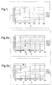
- Figure 1 shows as a function of the diffraction angle ⁇ the standardised intensities I of the diffraction orders of a conventional grating with a sinusoidal profile shape, wherein the light is incident perpendicularly.
- the grating has a number of lines of 1000 lines/mm and a profile height of 155 nm.
- the light of the three colours is diffracted into discrete angles ⁇ m which are far apart. There are two positive diffraction orders for the blue light, while there is only one for the green and the red light.
- the grating has a sinusoidal and thus symmetrical profile shape, the same amount of light is also diffracted into negative diffraction angles ⁇ -m .
- the grating is turned and/or tilted, a viewer sees the surface occupied by the grating in changing colours.
- Figures 2a and 2b show the standardised intensities of the diffraction orders for two gratings embodying the invention with a sawtooth-shaped profile shape.
- the gratings both have a number of lines of 150 lines/mm but different profile heights of 1.8 ⁇ m and 1.3 ⁇ m respectively. It is clearly apparent that the light of all three colours is diffracted with a high level of intensity into a narrow angle range ⁇ at about +32° and +26° respectively. In the first case the angle range ⁇ covers approximately angles ⁇ of 30° - 35°. Only very little light is diffracted into the other, both positive and negative, diffraction orders.
- the profile height can be reduced by a factor n to 1.2 ⁇ m and 0.89 ⁇ m respectively.
- the angle range ⁇ in which the viewer perceives the grating structures as being achromatic is determined by the number of lines: the smaller the number of lines, the narrower is the achromatic angle range.
- the diffraction angle ⁇ m with the highest level of intensity increases with the profile height or the angle of inclination of the sawtooth, with a predetermined number of lines, as can be seen from Figures 2a and 2b.
- the concentration of the diffracted light into a closely defined angle range ⁇ causes the illuminated surface portion to flash brightly when the observer tilts or turns the surface pattern. That effect cannot be achieved with other known optical-diffraction surface reliefs as there the light is diffracted in spectrally resolved form into a relatively large angle range.
- the grating with such a large profile height cannot be copied with a holographic contact copy to produce a surface relief as with the holographic contact copy the profile height of the relief, for example resulting in photoresist, would typically be only about 0.1 to 0.2 ⁇ m.
- other forms of the holographic copy procedure for producing a surface relief see for example the description of the contact copy process and the two-step process in S.P.
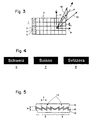
- the azimuth angle ⁇ denotes relative to a reference direction 9 an orientation direction 10 within the plane of the surface pattern 1.
- the direction 11 denotes the direction of incidence of light which is incident on the surface pattern 1
- a cone 12 denotes the angle range ⁇ into which light diffracted at the surface portions 3 of the representation 6 is predominantly focussed.
- Figure 4 shows the three representations 6, 7 and 8 which represent the graphics "Schweiz”, “Suisse” and “Svizzera”.
- the graphics are light on a dark background.
- the representations 6, 7 and 8 are also subdivided matrix-like into small n*m grid areas which are either light or dark.
- a surface portion 3 ( Figure 3) is associated with each grid area of the representation 6,
- a surface portion 4 is associated with each grid area of the representation 7, and so forth.
- the associated surface portion 3 contains a matt structure which diffusely scatters the incident light, or a flat, non-inclined mirror surface so that it appears dark for all angles or for all angles with the exception of the reflection angle. If the grid area is light, the associated surface portion 3 contains a grating structure 13 ( Figure 5) which diffracts the light incident in the predetermined direction of incidence 11 ( Figure 3), predominantly into the angle range ⁇ represented by the cone 12. The orientation and the spread angle ⁇ of the cone 12 are defined by the azimuth angle ⁇ 1 of the grating structure 13 or the profile shape and the profile height of the grating structure 13.
- the grating structure 13 of the surface portions 3 has a comparatively small number of lines of typically 100 to 250 lines per millimetre and an asymmetrical profile shape, preferably a sawtooth profile shape, as is shown in Figure 5.
- an asymmetrical profile shape typically at least ten diffraction orders occur for visible light.
- the profile shape is now predetermined in such a way that the light in the visible range is diffracted with a high level of diffraction efficiency into as few as possible but high diffraction orders. Admittedly under some circumstances light is also somewhat diffracted into the other diffraction orders. The intensity thereof is very low so that it is not noticeable to a viewer.
- the achromatic behaviour on the part of the grating structure 13 is achieved in the predetermined angle range ⁇ : in the angle range ⁇ the representation 6 appears light while outside the angle range ⁇ the representation 6 is not visible.
- no observable changing colour effects as are typical in relation to optical-diffraction structures occur when the surface pattern 1 is turned and/or tilted.
- the term turn is used to mean that the surface pattern is turned about an axis which is perpendicular to the plane of the surface pattern.
- the term tilt is used to mean that the surface pattern is turned about an axis which is disposed in the plane thereof.
- the representation 7 is embodied with a similar grating structure 13 to that of the representation 6.
- the azimuth angle ⁇ thereof involves an angle difference of preferably 180° relative to the azimuth angle ⁇ 1 , of the representation 6 so that the representation 7 is visible from a different solid angle range, in which case it can also be perceived as an image composed of light and dark, achromatic points. It is possible to conceive of different image contents for the representations 6 and 7 from those adopted in Figure 4, in which the angle difference of 180° provides advantageous effects.
- the prerequisite for nonetheless only a respective one of the two representations 6, 7 being perceptible is a high degree of asymmetry of the relationship of the light which is diffracted into positive diffraction orders and the light which is diffracted into negative diffraction orders. That ratio is typically at least 100:1 with a profile shape for the grating structure 13, which is optimised in relation to asymmetry.
- the representation 8 is made with a grating structure 13 which has a higher number of lines of typically 800 and more lines per millimetre. By virtue of that high number of lines the representation 8 has pronounced optical-diffraction effects, that is to say changing colours with a high level of luminosity when the surface pattern 1 is turned and/or tilted.
- the surface pattern 1 is advantageously in the form of a composite laminate.
- the composite laminate is formed by a first lacquer layer 14, a reflection layer 15 and a second lacquer layer, the cover layer 16.
- the totality of the grating structures 13 and the matt structures of the surface portions 3 - 5 are embodied in the form of microscopically fine relief structures.
- the lacquer layer 14 is advantageously an adhesive layer so that the composite laminate can be glued directly onto a substrate.
- the cover layer 16 advantageously completely levels off the relief structures. In addition in the visible range it preferably has an optical refractive index of at least 1.5 so that the geometrical profile height h gives an optically effective profile height which is as large as possible.
- the cover layer 16 also serves as a scratch-resistant protective layer.
- the subdivision of the representations 6 ( Figure 4), 7, etc. into grid areas does not have to be regular. That depends on the motifs of the representations 6, 7 etc.
- the surface portions 3 ( Figure 3), 4, etc. may also locally vary in shape and size. In order for example to increase a locally higher degree of brightness of a predetermined grid area of the representation 6, the surface portion 3 associated with the grid area of that representation may be increased within certain limits at the expense of the adjacent surface portions 4 or 5 of the other representations 7 or 8.
- Each representation 6, 7 and so forth includes light and dark image regions.
- associated with the light image regions are surface portions 3, 4 and so forth with a grating structure 13 ( Figure 5) with predetermined grating parameters.
- the surface of the representations 6, 7 and so forth, which is occupied by the dark image regions, is provided on the surface pattern 1 ( Figure 1) either in the form of a surface portion with a matt structure or in the form of a reflecting non-inclined surface portion or is associated as a surface portion 3, 4 and so forth with a grating structure 13 with other grating parameters, with a light image region of another representation 6, 7 and so forth.
- the surface portion 3, 4 and so forth associated with a dark image region of the representations 6, 7 and so forth also includes a diffracting relief structure.
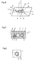
- Figure 6 shows two surface portions 3a and 3b of the surface pattern 1, wherein the surface portions 3a are associated with light image regions of the representation 6 ( Figure 4) while the surface portions 3b are associated with dark image regions thereof.
- the surface portion 3a contains a microscopically fine relief structure which diffracts perpendicularly incident light 17 into a first direction 18 in space, which is defined by the pair of angles ( ⁇ 1 , ⁇ 1 ).
- the surface portion 3b contains a microscopically fine relief structure which diffracts perpendicularly incident light into a second direction 19 in space which is defined by the pair of angles ( ⁇ 2 , ⁇ 2 ) .
- is typically at least 45°.
- each surface portion 3a, 3b and 4 has a largest linear dimension of at most 0.3 mm so that it is perceptible by eye at most as a structure-less point.
- the second representation 7 ( Figure 4) comprises two different motifs which are disposed in side-by-side relationship and do not overlap.
- the two motifs are to be visible from different viewing directions.
- both motifs to be disposed in the surface portions 4 which are associated with the grid areas of the second representation.
- the parameters of the relief structures of the first motif and those of the second motif are then different and can be established independently of each other.
- the same solution can also be used in relation to more than two motifs which do not overlap.
- the surface portion 4 associated with a dark grid area of the second representation 7 may contain the same relief structure as the adjacent surface portion 3 ( Figure 3) which is associated with a light grid area of the first representation 6. That makes it possible to increase the brightness of the corresponding grid area of the representation 6. That way of enhancing brightness is possible within the limits defined by the graphic contours of the representations 6, 7.
- Figure 7 shows the surface pattern 1 which as an example of the graphic configuration has a large rectangle, a triangle, a circular area and a small square.
- the triangle, the circular area and the square are arranged within the large rectangle without overlapping.
- the large rectangle corresponds to the first representation 6 ( Figure 4)
- the triangle corresponds to the second representation 7
- the circular area corresponds to the third representation 8
- the square corresponds to a fourth representation.
- Those surface parts of the large rectangle which are not covered by the triangle, the circular area or the square represent a single surface portion 3 or are subdivided into surface portions 3 and 20.
- the area occupied by the triangle contains surface portions 3, 4 and 20.
- the circular area contains surface portions 3, 5 and 20.
- the area occupied by the square represents a single surface portion 21.
- the surface portions 3 contain a grating with a number of lines of 1000 lines/mm and a symmetrical profile shape so that the large rectangle exhibits rainbow colour effects when the surface pattern 1 is turned and/or tilted.
- the surface portions 4 contain a grating with a number of lines of 250 lines/mm whose azimuth angle is ⁇ 1 ( Figure 6) and which has an asymmetrical profile shape whose profile height is so predetermined that the triangle appears achromatically light to a viewer looking from the predetermined direction 18 in space ( Figure 6). In other directions in space, the triangle is scarcely visible as the surface portions 3 appear substantially lighter than the surface portions 4.
- the surface portions 20 contain a matt structure or a mirror surface which is flat relative to the plane of the surface pattern 1.
- the surface portions 5 contain the same grating as the surface portions 4, but with another orientation in respect of the azimuth angle ⁇ 2 ( Figure 6) .
- the circular area thus appears achromatically light from another direction 19 in space ( Figure 6).
- the surface portion 21 of the square also contains a relief structure which appears achromatically light from another predetermined direction in space.
- the relationship of the area proportions of the surface portions 3, 4, 5 and 20 determines the relative brightness of the four different representations. The greatest brightness is exhibited by the square whose full area is provided with a relief structure with an asymmetrical profile shape, which has a high level of diffraction efficiency.
- the levels of brightness of the triangle and the circular area, as well as the large rectangle essentially depend on the proportional size of the area occupied by the surface portions 20.
- the relative brightnesses thereof can thus be controlled by means of using surface portions 20.
- the individual surface portions 3, 4, 5 and 20 are of linear dimensions of at most 0.3 mm so that they are not individually perceptible by eye from a normal viewing distance of 30cm. In the illustrated example they are shown on an enlarged scale for reasons relating to clarity of the drawing. The pronounced achromatic effect, the asymmetry of the diffraction effects and relative brightness levels serve as different security features.
- Relief structures which produce an achromatic effect can also be used for a surface pattern 1 in which subdivision of the representations into grid areas is not necessary or is not meaningful.
- Figure 8 shows the surface pattern 1 with a star comprising at least two narrow lines 22, 23 which do not cross each other.
- the lines 22, 23 belong to two different representations,that is to say the line 22 is to be visible from a different viewing direction from the line 23.
- the line 22 has a first relief structure and the line 23 has a second relief structure to produce an achromatic effect, wherein the parameters of the two relief structures are selected to be different so that the lines 22 and 23 are visible from different directions in space.
- the star When the surface pattern is turned and/or tilted the star therefore exhibits a kinematic effect insofar as the brightness levels of the lines 22 and 23 change.
- the kinematic effect can be refined with an increasing number of lines 22, 23.
- the surface pattern 1 can be subdivided into surface portions 3 ( Figure 3), 4, 5 and so forth of any shape which do not have to be either continuous or mutually adjoining, wherein groups of surface portions 3, 4, 5 and so forth which have the same relief structure are associated with predetermined representations 6 ( Figure 4), 7, 8 and so forth.
- predetermined representations 6 Figure 4
- Figure 4 predetermined representations 6
- Figure 4 7, 8 and so forth.
- the area of the surface pattern 1, which remains between the lines of the various representations can be in the form of a matt or a reflecting surface.
- the surface pattern 1 which has representations consisting of lines can be produced in a technologically simple manner in accordance with the teachings of European patent specification EP 330 738 or Swiss patent specification CH 664 030.
- the representation 6 ( Figure 4) contains a first motif with a grating structure which achromatically diffracts impinging light into the predetermined angle range ⁇ and a second motif with a grating structure which for example diffracts the green spectral component of the impinging light into a direction which is within the angle range ⁇ , then the two motifs reference each other in a manner which is easily recognisable for an observer.
Abstract
Description
- The invention relates to an optically variable surface pattern of the kind set forth in the classifying portion of
claim 1. - Such optically variable surface patterns with a microscopically fine relief structure are suitable for example for increasing the level of security against forgery and for conspicuously identifying articles of all kinds and can be used in particular in relation to value-bearing papers or bonds, identity cards, payment means and similar articles to be safeguarded.
- A surface pattern of the kind set forth in the classifying portion of
claim 1 is known from EP 375 833. The surface pattern which is embossed in the form of a light-modifying relief structure into a carrier is subdivided into grid areas. Each grid area is divided into a number n of surface portions, wherein each surface portion is associated with a pixel of one of n representations and wherein each has a respective diffraction element which contains items of information about a chromaticity, a brightness value and a viewing direction. The n representations are composed of beams of diffracted light which become visible at n different viewing directions. In order that a representation becomes visible only at a single viewing direction the corresponding relief structures are of an asymmetrical profile shape. - EP 360 969 discloses a diffraction element which has surface portions with colours of high luminosity. The surface portions contain relief structures which are in the form of diffraction gratings with an asymmetrical profile shape, for example with a sawtooth-shaped profile configuration. The diffraction gratings reflect incident light predominantly in the first diffraction order. For that reason the diffraction gratings change their colour with a varying direction of incidence of the light and a varying direction of view on the part of an observer. The achievable degree of asymmetry, that is to say the ratio of the level of intensity of the light diffracted into the plus first diffraction order to the intensity of the light diffracted into the minus first diffraction order is typically 3:1 and at most 30:1.
- DE 25 55 214 discloses optical markings which modify incident light essentially not by diffraction but by reflection or optical refraction on the basis of the laws of geometrical optics. With line spacings of 10 to 100 microns however those configurations already give profile heights of several or several tens of micrometres, at moderate reflection angles.
- It is known from the technical literature, for example from the book "Diffraction Gratings", M.C. Hutley,
Chapter 2, pages 13-56, ISBN 0-12-362980-2 that light of a wavelength λ which is incident on a grating structure from a direction of incidence is diffracted in accordance with the following relationship:grating structure 1, the green spectral component of thegrating structure 2 and the blue spectral component of thegrating structure 3 are the same for a diffraction direction. The individual grating structures do not have to be arranged in mutually juxtaposed relationship but they can also be in mutually superposed relationship as for example in the case of holograms. Juxtaposition can also be replaced by a local, repetitive variation of the grating constant: the surface which is to appear achromatic is subdivided into individual surface portions whose dimensions are below the resolution limit of the human eye. Within a surface portion the local grating period (line spacing) varies in accordance with a predefined, for example linear function, over a given period range. It is further known in regard to an achromatic hologram for the grating period to be locally stochastically altered, see for example the book "Optical Holography", edited by P.Harriharan, Cambridge Studies in Modern Optics, pages 144 ff,ISBN 0 521 31162 2. - All those methods suffer from the common disadvantage that, although an achromatic impression can admittedly be produced for a predetermined viewing angle, pronounced colour fringes appear in the adjoining viewing angles. If moreover the viewing range over which a representation is to appear achromatic is increased by a large period extent, the brightness which can be perceived by an observer decreases noticeably as the incident light is distributed over a correspondingly larger angular range.
- According to the present invention there is provided an optically variable surface pattern as set forth in
claim 1. - Embodiments of the present invention provide an optically variable surface pattern which is difficult to forge, with at least one representation of a graphic configuration, wherein the representation produces an achromatic impression when viewed in visible light over a certain angular range without noticeable colour fringes occurring in the adjoining angular ranges.
- For the purposes of describing the general idea of the invention, let it be established as the initial situation that a surface pattern contains at least n = 2 representations. The surface pattern is therefore subdivided into first and second surface portions. The first surface portions serve to produce the first representation and the second surface portions serve to produce the second representation. Both representations are to be achromatic, that is to say they are to be visible in the colour of the light illuminating them and they are also not to produce changing colour effects when the surface pattern is turned or tilted. In accordance with geometrically optical notions, the specified object is attained in that the surface portions belonging to the first representation are in the form of reflecting surfaces which are inclined through a first predetermined angle of inclination α1 with a first predetermined azimuthal orientation
Φ1 with respect to the plane of the surface pattern, or they are in the form of diffusely scattering matt structures. Instead of a diffusely scattering matt structure, it is also possible to provide a mirror surface which is disposed in the plane of the surface pattern. The reflecting surfaces belonging to the second representation are inclined relative to the plane of the surface pattern in another azimuthal orientation Φ1 through a second angle of inclination α2. With the predetermined viewing direction an inclined surface portion produces a light pixel whereas a matt structure or mirror surface produces a dark pixel. With an angle of inclination of 15° and an extent of the surface portions of a maximum of 100 micrometres however there are differences in respect of height relative to the plane of the surface pattern of about 27 micrometres. Therefore each inclined surface portion is broken down into an organisation of narrower surface portions which are arranged in parallel side-by-side relationship, with the same angle of inclination α1 and α2 respectively. This organisation which replaces the original surface portion is a relief structure and in cross-section is of a sawtooth-shaped profile whose grating period and profile height are matched to each other in such a way that the light diffracted at the sawtooth-shaped profile of the relief structure behaves in a first approximation similarly to the light reflected at the original inclined surface portion. Such a behaviour is achieved if the profile height of the sawtooth is approximately an integral multiple of half the optical path length of the light, in which respect that condition is possibly to be adapted to the angle of incidence of the light. That condition is approximately simultaneously met for an optical path length of 3.3 or 7.15 micrometres for example for the three wavelengths in the visible range λ1 = 450
nm, λ2 = 550 nm and λ3 = 650 nm. If the reflecting surface is covered with a lacquer layer with an optical refractive index of 1.5, that gives a profile height which is reduced by the factor n = 1.5, of 1.1 and 2.37 micrometres respectively. - In the case of a surface pattern embodying the invention each of the two representations is visible from only one viewing direction, in which case the two representations do not interfere with each other.
- From an optical-diffraction point of view embodiments of the invention afford the teaching of using grating structures with a large grating period, that is to say a small number of lines, so that many diffraction orders can occur in the visible range, to produce an achromatic optical impression in respect of the two representations. In addition the profile shape is to be such that the maximum possible proportion of the diffracted light is diffracted into higher diffraction orders. So that the ratio between the light which is diffracted into positive diffraction orders and the light which is diffracted into negative diffraction orders is as high as possible, grating structures with an asymmetrical profile shape and in particular a sawtooth profile shape are to be used. These ideas are described in greater detail hereinafter.
- In the case of grating structures with a small number of lines many diffraction orders can exist in accordance with equation (1). With a number of lines of 100 lines/mm and with a wavelength of λ = 550 nm, with perpendicular incidence the diffraction orders m = -18, -17, -16, ...-1, 0, +1, ..., +17, +18 can occur, that is to say 37 diffraction orders within the full diffraction angle range of -90° to +90°. The angle spacing between adjacent diffraction orders is typically 3 - 4°.
- The diffraction angles m are determined in accordance with equation (1) by the period d of the grating structure. The levels of intensity of the light which is diffracted into the various discrete diffraction orders are determined by the profile shape and the profile height of the grating structure. By suitable selection of those two parameters, it is possible to control the distribution of intensity of the diffracted light in such a way that light of the wavelength λ is diffracted for the major part into diffraction orders whose diffraction angles m are close together in a narrow angle range ψ. The incident polychromatic light is also diffracted into the narrow angle range ψ for all different wavelengths λ. The grating structure therefore appears to the viewer within the angle range ψ light and achromatic, in the colour of the light illuminating the grating structure, while it is dark outside the angle range ψ.
- Figure 1 shows as a function of the diffraction angle the standardised intensities I of the diffraction orders of a conventional grating with a sinusoidal profile shape, wherein the light is incident perpendicularly. The grating has a number of lines of 1000 lines/mm and a profile height of 155 nm. The spectra are calculated for the three wavelengths λ1= 450 nm, λ2 = 550 nm and λ3 = 650 nm, corresponding to the colours blue, green and red. The light of the three colours is diffracted into discrete angles m which are far apart. There are two positive diffraction orders for the blue light, while there is only one for the green and the red light. As the grating has a sinusoidal and thus symmetrical profile shape, the same amount of light is also diffracted into negative diffraction angles -m. When the grating is turned and/or tilted, a viewer sees the surface occupied by the grating in changing colours.
- Figures 2a and 2b show the standardised intensities of the diffraction orders for two gratings embodying the invention with a sawtooth-shaped profile shape. The gratings both have a number of lines of 150 lines/mm but different profile heights of 1.8 µm and 1.3 µm respectively. It is clearly apparent that the light of all three colours is diffracted with a high level of intensity into a narrow angle range ψ at about +32° and +26° respectively. In the first case the angle range ψ covers approximately angles of 30° - 35°. Only very little light is diffracted into the other, both positive and negative, diffraction orders. Practically no light is also diffracted into the angle range at -32° and -26° respectively as, because of the asymmetrical profile shape of the corresponding grating, it is readily possible to achieve a ratio of the light which is diffracted into the positive diffraction orders to the light which is diffracted into the negative diffraction orders, of at least 100:1. Therefore, each of those two gratings appears to a viewer in a relatively narrow angle range ψ as an achromatic surface while in the remaining angle ranges it appears as a dark surface, without noticeable colour fringes occurring when the grating is turned and/or tilted. If the gratings are covered with a lacquer layer with a refractive index of n = 1.5 the profile height can be reduced by a factor n to 1.2 µm and 0.89 µm respectively. By virtue of the selected profile shape and profile height of the gratings the light is diffracted into high positive diffraction orders with a high level of efficiency, more specifically green light approximately into the plus tenth.
- The angle range ψ in which the viewer perceives the grating structures as being achromatic is determined by the number of lines: the smaller the number of lines, the narrower is the achromatic angle range. The diffraction angle m with the highest level of intensity increases with the profile height or the angle of inclination of the sawtooth, with a predetermined number of lines, as can be seen from Figures 2a and 2b.
- As is to be noted from Figures 2a and 2b, discrete diffraction orders still occur, but only a few diffraction lines which are associated with the various spectral colours involve noticeable intensity within the angle range ψ, under normal illumination. Those diffraction lines are now so close together in terms of angle that the surface portion occupied by grating structures of that kind, when illuminated with white light and viewed from any direction within the angle range ψ, does not appear in changing colours but appears to the viewer as always remaining lit white or in other words as an achromatic surface.
- The concentration of the diffracted light into a closely defined angle range ψ causes the illuminated surface portion to flash brightly when the observer tilts or turns the surface pattern. That effect cannot be achieved with other known optical-diffraction surface reliefs as there the light is diffracted in spectrally resolved form into a relatively large angle range. In addition the grating with such a large profile height cannot be copied with a holographic contact copy to produce a surface relief as with the holographic contact copy the profile height of the relief, for example resulting in photoresist, would typically be only about 0.1 to 0.2µm. In addition other forms of the holographic copy procedure for producing a surface relief (see for example the description of the contact copy process and the two-step process in S.P. McGrew, Hologram Counterfeiting: Problems and Solutions, SPIE vol. 1210 Optical Security and Anticounterfeiting Systems 1990) also involve losing the pronounced asymmetry of the grating structure, which is also highly important so that the light is diffracted into high diffraction orders with a high level of efficiency. In addition a given profile shape is also a prerequisite for achieving the achromatic effect.
- Embodiments of the invention are now described in greater detail hereinafter with reference to the drawing in which:
- Figure 3
- shows a surface pattern,
- Figure 4
- shows three representations of graphic configuration,
- Figure 5
- shows the surface pattern in the form of a composite laminate with surface portions having a grating structure of a sawtooth-shaped profile shape,
- Figure 6
- shows details of a further surface pattern,
- Figure 7
- shows a further surface pattern, and
- Figure 8
- shows a surface pattern made up of lines.
- Figure 3 shows a
surface pattern 1 which is subdivided matrix-like into n*m areas or fields 2. Eacharea 2 is subdivided into k = 3surface portions surface portions areas 2 contains a respective one of k = 3representations orientation direction 10 within the plane of thesurface pattern 1. Thedirection 11 denotes the direction of incidence of light which is incident on thesurface pattern 1, acone 12 denotes the angle range ψ into which light diffracted at thesurface portions 3 of therepresentation 6 is predominantly focussed. - Figure 4 shows the three
representations representations representation 6, asurface portion 4 is associated with each grid area of therepresentation 7, and so forth. - If the grid area of the
representations 6 is dark, the associatedsurface portion 3 contains a matt structure which diffusely scatters the incident light, or a flat, non-inclined mirror surface so that it appears dark for all angles or for all angles with the exception of the reflection angle. If the grid area is light, the associatedsurface portion 3 contains a grating structure 13 (Figure 5) which diffracts the light incident in the predetermined direction of incidence 11 (Figure 3), predominantly into the angle range ψ represented by thecone 12. The orientation and the spread angle ψ of thecone 12 are defined by the azimuth angle Φ1 of thegrating structure 13 or the profile shape and the profile height of thegrating structure 13. Thegrating structure 13 of thesurface portions 3 has a comparatively small number of lines of typically 100 to 250 lines per millimetre and an asymmetrical profile shape, preferably a sawtooth profile shape, as is shown in Figure 5. By virtue of the small number of lines, typically at least ten diffraction orders occur for visible light. The profile shape is now predetermined in such a way that the light in the visible range is diffracted with a high level of diffraction efficiency into as few as possible but high diffraction orders. Admittedly under some circumstances light is also somewhat diffracted into the other diffraction orders. The intensity thereof is very low so that it is not noticeable to a viewer. As the light is diffracted for the major part into diffraction angles m of higher order m and as the diffractions angles m for different wavelengths, for example λ1 = 450nm, λ2 = 550nm and λ3 = 650 nm overlap, the achromatic behaviour on the part of thegrating structure 13 is achieved in the predetermined angle range ψ: in the angle range ψ therepresentation 6 appears light while outside the angle range ψ therepresentation 6 is not visible. In addition, no observable changing colour effects as are typical in relation to optical-diffraction structures occur when thesurface pattern 1 is turned and/or tilted. The term turn is used to mean that the surface pattern is turned about an axis which is perpendicular to the plane of the surface pattern. The term tilt is used to mean that the surface pattern is turned about an axis which is disposed in the plane thereof. To sum up it is found that therepresentation 6 can only be viewed from the predetermined solid angle range ψ with a fixed direction ofincidence 11 of the light. In that case therepresentation 6 appears in the form of an image consisting of light and dark points which generally involve the colour of the reflection layer (Figure 5) used to cover thegrating structures 13 and/or the cover layer 16 (Figure 5). - The
representation 7 is embodied with a similargrating structure 13 to that of therepresentation 6. The azimuth angle Φ thereof however involves an angle difference of preferably 180° relative to the azimuth angle Φ1, of therepresentation 6 so that therepresentation 7 is visible from a different solid angle range, in which case it can also be perceived as an image composed of light and dark, achromatic points. It is possible to conceive of different image contents for therepresentations representations grating structure 13, which is optimised in relation to asymmetry. - The
representation 8 is made with agrating structure 13 which has a higher number of lines of typically 800 and more lines per millimetre. By virtue of that high number of lines therepresentation 8 has pronounced optical-diffraction effects, that is to say changing colours with a high level of luminosity when thesurface pattern 1 is turned and/or tilted. - It is not entirely impossible for the
representations cone 12 into the invisible angle range. There is however the central region of thecone 12 in which the image impression is pronouncedly achromatic. In the case of therepresentation 8 in contrast there is no achromatic range, but thatrepresentation 8 appears in a colour which is well-defined from the optical-diffraction point of view, in any viewing angle. - As shown in Figure 5 in cross-section, the
surface pattern 1 is advantageously in the form of a composite laminate. The composite laminate is formed by afirst lacquer layer 14, areflection layer 15 and a second lacquer layer, thecover layer 16. The totality of thegrating structures 13 and the matt structures of the surface portions 3 - 5 are embodied in the form of microscopically fine relief structures. Thelacquer layer 14 is advantageously an adhesive layer so that the composite laminate can be glued directly onto a substrate. Thecover layer 16 advantageously completely levels off the relief structures. In addition in the visible range it preferably has an optical refractive index of at least 1.5 so that the geometrical profile height h gives an optically effective profile height which is as large as possible. Thecover layer 16 also serves as a scratch-resistant protective layer. - The subdivision of the representations 6 (Figure 4), 7, etc. into grid areas does not have to be regular. That depends on the motifs of the
representations representation 6, thesurface portion 3 associated with the grid area of that representation may be increased within certain limits at the expense of theadjacent surface portions other representations - The subdivision of the
representations representation surface portions representations surface portion grating structure 13 with other grating parameters, with a light image region of anotherrepresentation surface portion representations - Figure 6 shows two
surface portions 3a and 3b of thesurface pattern 1, wherein the surface portions 3a are associated with light image regions of the representation 6 (Figure 4) while thesurface portions 3b are associated with dark image regions thereof. The surface portion 3a contains a microscopically fine relief structure which diffracts perpendicularly incident light 17 into afirst direction 18 in space, which is defined by the pair of angles (Φ1, 1). Thesurface portion 3b contains a microscopically fine relief structure which diffracts perpendicularly incident light into asecond direction 19 in space which is defined by the pair of angles (Φ2, 2) . The absolute difference between the two azimuth angles |Φ1 - Φ2| is typically at least 45°. That provides that, when light is incident perpendicularly, the surface portion 3a appears light and thesurface portion 3b appears dark to a viewer looking onto thesurface pattern 1 from thedirection 18 in space. In contrast the surface portion 3a appears dark and thesurface portion 3b appears light to a viewer looking onto thesurface pattern 1 from thedirection 19 in space. Therepresentation 6 is thus perceptible with reversed contrast from the twodirections surface portion - In a further embodiment for example the second representation 7 (Figure 4) comprises two different motifs which are disposed in side-by-side relationship and do not overlap. The two motifs are to be visible from different viewing directions. In that case it is possible for both motifs to be disposed in the
surface portions 4 which are associated with the grid areas of the second representation. The parameters of the relief structures of the first motif and those of the second motif are then different and can be established independently of each other. The same solution can also be used in relation to more than two motifs which do not overlap. - In addition for example the
surface portion 4 associated with a dark grid area of the second representation 7 (Figure 4) may contain the same relief structure as the adjacent surface portion 3 (Figure 3) which is associated with a light grid area of thefirst representation 6. That makes it possible to increase the brightness of the corresponding grid area of therepresentation 6. That way of enhancing brightness is possible within the limits defined by the graphic contours of therepresentations - Figure 7 shows the
surface pattern 1 which as an example of the graphic configuration has a large rectangle, a triangle, a circular area and a small square. The triangle, the circular area and the square are arranged within the large rectangle without overlapping. The large rectangle corresponds to the first representation 6 (Figure 4), the triangle corresponds to thesecond representation 7, the circular area corresponds to thethird representation 8 and the square corresponds to a fourth representation. Those surface parts of the large rectangle which are not covered by the triangle, the circular area or the square represent asingle surface portion 3 or are subdivided intosurface portions surface portions surface portions single surface portion 21. Thesurface portions 3 contain a grating with a number of lines of 1000 lines/mm and a symmetrical profile shape so that the large rectangle exhibits rainbow colour effects when thesurface pattern 1 is turned and/or tilted. Thesurface portions 4 contain a grating with a number of lines of 250 lines/mm whose azimuth angle is Φ1 (Figure 6) and which has an asymmetrical profile shape whose profile height is so predetermined that the triangle appears achromatically light to a viewer looking from thepredetermined direction 18 in space (Figure 6). In other directions in space, the triangle is scarcely visible as thesurface portions 3 appear substantially lighter than thesurface portions 4. Thesurface portions 20 contain a matt structure or a mirror surface which is flat relative to the plane of thesurface pattern 1. Thesurface portions 5 contain the same grating as thesurface portions 4, but with another orientation in respect of the azimuth angle Φ2 (Figure 6) . The circular area thus appears achromatically light from anotherdirection 19 in space (Figure 6). Thesurface portion 21 of the square also contains a relief structure which appears achromatically light from another predetermined direction in space. The relationship of the area proportions of thesurface portions surface portions 20. The relative brightnesses thereof can thus be controlled by means of usingsurface portions 20. With the exception of the area occupied by the square theindividual surface portions - Relief structures which produce an achromatic effect can also be used for a
surface pattern 1 in which subdivision of the representations into grid areas is not necessary or is not meaningful. Figure 8 shows thesurface pattern 1 with a star comprising at least twonarrow lines lines line 22 is to be visible from a different viewing direction from theline 23. Theline 22 has a first relief structure and theline 23 has a second relief structure to produce an achromatic effect, wherein the parameters of the two relief structures are selected to be different so that thelines lines lines - Stated in generalised terms the
surface pattern 1 can be subdivided into surface portions 3 (Figure 3), 4, 5 and so forth of any shape which do not have to be either continuous or mutually adjoining, wherein groups ofsurface portions surface pattern 1 in particular representations which, similarly to conventional engraving, are made up of a plurality of lines. If lines of different representations overlap that nonetheless does not give troublesome optical effects as the area occupied by the points of intersection is very small in terms of proportion. The area of thesurface pattern 1, which remains between the lines of the various representations, can be in the form of a matt or a reflecting surface. - The
surface pattern 1 which has representations consisting of lines can be produced in a technologically simple manner in accordance with the teachings of European patent specification EP 330 738 or Swiss patent specification CH 664 030. - It will be appreciated that it is possible for the achromatic representations to have superimposed thereon motifs which in terms of proportion advantageously occupy only a very small area such as for example guilloche patterns or microscripts which exhibit kinematic colour effects. Such kinematic optical effects are known from European patent documents EP 105 099, EP 375 833 or EP 490 923 and products which are marketed under the name KINEGRAM®. If the representation 6 (Figure 4) contains a first motif with a grating structure which achromatically diffracts impinging light into the predetermined angle range ψ and a second motif with a grating structure which for example diffracts the green spectral component of the impinging light into a direction which is within the angle range ψ, then the two motifs reference each other in a manner which is easily recognisable for an observer. It is clear from Figures 1 and 2a that such referencing is possible for example with a sawtooth-shaped grating with a number of lines of 150 lines/mm and a profile height of 1.2 µm and a sinusoidal grating with 1000 lines/mm and a profile height of 0.155/1.5 = 0.1 µm if the gratings are covered with the lacquer layer 16 (Figure 5) with a refractive index n = 1.5. The two grating structures are arranged in the surface portions 3 (Figure 3) which belong to the
representation 6. In the case of holographic copying processes at least the diffraction angles of the two grating structures change in different ways so that the effect of the referencing is lost.
Claims (7)
- An optically variable surface pattern (1) with at least one representation (6; 7; 8) of graphic configuration and comprising comparatively light and dark image regions, wherein associated with the light image regions of each representation (6; 7; 8) are surface portions (3-5, 22, 23) with grating structures (13) which have an optical diffraction effect and which involve different grating parameters, so that the representations (6; 7; 8) are visible at different viewing directions upon being illuminated with visible light characterised in that the surface portions (3-5, 22, 23) of at least one of the representations (6; 7) have first grating structures (13) with a number of lines of less than 250 lines per millimetre and that the first grating structures (13) have a profile shape such that the light image regions of said representation (6; 7) appear achromatically in a predetermined angle range ψ.
- A surface pattern according to claim 1 characterised in that the profile shape of the first grating structures (13) is asymmetrical.
- A surface pattern according to claim 2 characterised in that the profile shape of the first grating structures (13) is sawtooth-shaped.
- A surface pattern according to one of claims 1 to 3 characterised in that the optical profile height h, which is the product of the geometrical profile height and the index of refraction of an optional cover layer (16) which may cover the grating structures (13), of the first grating structures (13) is at least 0.5 micrometre.
- A surface pattern according to one of claims 1 to 4 characterised in that surface portions (3a) of a first kind are associated with the light image regions of at least one representation (6; 7; 8) and surface portions (3b) of a second kind are associated with the dark image regions of said representation (6; 7; 8) so that the representation (6; 7; 8) is visible in reversed contrast from two predetermined viewing directions.
- A surface pattern according to one of claims 1 to 5 characterised in that at least one representation (6; 7; 8) includes at least two non-overlapping motifs which are visible from different viewing directions (18, 19).
- A surface pattern according to one of claims 1 to 6 characterised in that at least one of the surface portions (3-5, 22, 23) contains a first grating structure which diffracts light almost independently of its wavelength into a predetermined angle range ψ and that a further one of the surface portions (3-5, 22, 23) contains a second grating structure which diffracts light of different wavelengths λ in spectrally resolved manner in directions whose diffraction angles are close to or fall into the angle range ψ.
Priority Applications (2)
| Application Number | Priority Date | Filing Date | Title |
|---|---|---|---|
| EP96939861A EP0868313B1 (en) | 1995-11-28 | 1996-11-20 | Optically variable surface pattern |
| SI9630223T SI0868313T1 (en) | 1995-11-28 | 1996-11-20 | Optically variable surface pattern |
Applications Claiming Priority (7)
| Application Number | Priority Date | Filing Date | Title |
|---|---|---|---|
| CH336895 | 1995-11-28 | ||
| CH3368/95 | 1995-11-28 | ||
| CH336895 | 1995-11-28 | ||
| EP96102497 | 1996-02-20 | ||
| EP96102497 | 1996-02-20 | ||
| EP96939861A EP0868313B1 (en) | 1995-11-28 | 1996-11-20 | Optically variable surface pattern |
| PCT/EP1996/005114 WO1997019821A1 (en) | 1995-11-28 | 1996-11-20 | Optically variable surface pattern |
Publications (2)
| Publication Number | Publication Date |
|---|---|
| EP0868313A1 EP0868313A1 (en) | 1998-10-07 |
| EP0868313B1 true EP0868313B1 (en) | 2000-04-19 |
Family
ID=25692846
Family Applications (1)
| Application Number | Title | Priority Date | Filing Date |
|---|---|---|---|
| EP96939861A Expired - Lifetime EP0868313B1 (en) | 1995-11-28 | 1996-11-20 | Optically variable surface pattern |
Country Status (8)
| Country | Link |
|---|---|
| US (1) | US6157487A (en) |
| EP (1) | EP0868313B1 (en) |
| AT (1) | ATE191887T1 (en) |
| AU (1) | AU7694196A (en) |
| CA (1) | CA2233720C (en) |
| DE (1) | DE69607857T2 (en) |
| SI (1) | SI0868313T1 (en) |
| WO (1) | WO1997019821A1 (en) |
Cited By (5)
| Publication number | Priority date | Publication date | Assignee | Title |
|---|---|---|---|---|
| DE102010049600A1 (en) | 2010-10-26 | 2012-01-19 | Giesecke & Devrient Gmbh | Security element with optically variable surface pattern |
| DE102010048262A1 (en) | 2010-10-12 | 2012-04-12 | Giesecke & Devrient Gmbh | presentation element |
| DE102010049617A1 (en) | 2010-10-26 | 2012-04-26 | Giesecke & Devrient Gmbh | Security element with optically variable surface pattern |
| US8964296B2 (en) | 2010-05-07 | 2015-02-24 | Giesecke & Devrient Gmbh | Method for producing a microstructure on a carrier |
| DE102022000210A1 (en) | 2022-01-20 | 2023-07-20 | Giesecke+Devrient Currency Technology Gmbh | Security feature for documents of value and document of value with a security feature |
Families Citing this family (40)
| Publication number | Priority date | Publication date | Assignee | Title |
|---|---|---|---|---|
| DE19924750C2 (en) * | 1999-04-08 | 2002-11-14 | Ovd Kinegram Ag Zug | Reading arrangement for information strips with optically coded information |
| US6516152B1 (en) * | 1999-05-13 | 2003-02-04 | Minolta Co., Ltd. | Focusing screen for use in camera |
| DE19928060A1 (en) * | 1999-06-15 | 2000-12-21 | Whd Elektron Prueftech Gmbh | Optically variable security feature and process for its manufacture |
| US20040032659A1 (en) * | 2000-07-18 | 2004-02-19 | Drinkwater John K | Difractive device |
| US20100085642A1 (en) * | 2000-07-18 | 2010-04-08 | Optaglio Limited | Diffractive device |
| DE10129939B4 (en) * | 2001-06-20 | 2006-06-22 | Ovd Kinegram Ag | Optically variable surface pattern |
| DE50213436D1 (en) | 2001-12-22 | 2009-05-20 | Ovd Kinegram Ag | DIFFUSER SECURITY ELEMENT |
| GB0202646D0 (en) * | 2002-02-05 | 2002-03-20 | Optaglio Ltd | Secure hidden data protection optically variable label |
| DE10221491A1 (en) * | 2002-05-14 | 2003-12-04 | Kurz Leonhard Fa | Optically variable surface pattern |
| DE10232245B4 (en) * | 2002-07-17 | 2008-06-12 | Leonhard Kurz Gmbh & Co. Kg | Optically variable element with varying spacer layer thickness |
| DE10328759B4 (en) * | 2003-06-25 | 2006-11-30 | Ovd Kinegram Ag | Optical security element and system for visualizing hidden information |
| DE102004003984A1 (en) † | 2004-01-26 | 2005-08-11 | Giesecke & Devrient Gmbh | Lattice image with one or more grid fields |
| US7699351B2 (en) † | 2004-08-27 | 2010-04-20 | Kxo Ag | Security document with a volume hologram forming a partial motif |
| GB0504959D0 (en) | 2005-03-10 | 2005-04-20 | Rue International De La Ltd | Security device based on customised microprism film |
| DE102005027380B4 (en) * | 2005-06-14 | 2009-04-30 | Ovd Kinegram Ag | The security document |
| DE102005032997A1 (en) * | 2005-07-14 | 2007-01-18 | Giesecke & Devrient Gmbh | Lattice image and method for its production |
| DE102005061749A1 (en) * | 2005-12-21 | 2007-07-05 | Giesecke & Devrient Gmbh | Optically variable security element for making valuable objects safe has an achromatic reflecting micro-structure taking the form of a mosaic made from achromatic reflecting mosaic elements |
| DE102006012732A1 (en) * | 2006-03-17 | 2007-09-20 | Giesecke & Devrient Gmbh | grid image |
| GB0615921D0 (en) | 2006-08-10 | 2006-09-20 | Rue De Int Ltd | Photonic crystal security device |
| GB0615919D0 (en) | 2006-08-10 | 2006-09-20 | Rue De Int Ltd | Photonic crystal security device |
| DE102007022109A1 (en) | 2007-05-11 | 2008-11-13 | Prüfbau Dr.-Ing. H. Dürner GmbH | Device for generating a reflection hologram of high resolution |
| GB0711434D0 (en) | 2007-06-13 | 2007-07-25 | Rue De Int Ltd | Holographic security device |
| GB0720550D0 (en) | 2007-10-19 | 2007-11-28 | Rue De Int Ltd | Photonic crystal security device multiple optical effects |
| FR2942811B1 (en) | 2009-03-04 | 2011-05-06 | Oberthur Technologies | SECURITY ELEMENT FOR DOCUMENT-VALUE. |
| GB0911792D0 (en) | 2009-07-07 | 2009-08-19 | Rue De Int Ltd | Photonic crystal material |
| DE102009056934A1 (en) | 2009-12-04 | 2011-06-09 | Giesecke & Devrient Gmbh | Security element, value document with such a security element and manufacturing method of a security element |
| DE102010047250A1 (en) | 2009-12-04 | 2011-06-09 | Giesecke & Devrient Gmbh | Security element, value document with such a security element and manufacturing method of a security element |
| FR2953965B1 (en) | 2009-12-14 | 2011-11-25 | Arjowiggins Security | SECURITY ELEMENT COMPRISING AN OPTICAL STRUCTURE |
| DE102010049831A1 (en) * | 2010-10-27 | 2012-05-03 | Giesecke & Devrient Gmbh | Optically variable surface pattern |
| DE102011014114B3 (en) | 2011-03-15 | 2012-05-10 | Ovd Kinegram Ag | Multi-layer body and method for producing a multi-layer body |
| CN102722096B (en) * | 2011-03-30 | 2016-05-11 | 武汉思臻光信息科技有限公司 | A kind of for generating the method and system of holographic interference fringes |
| DE102011108242A1 (en) | 2011-07-21 | 2013-01-24 | Giesecke & Devrient Gmbh | Optically variable element, in particular security element |
| GB201400910D0 (en) | 2014-01-20 | 2014-03-05 | Rue De Int Ltd | Security elements and methods of their manufacture |
| DE102014019088A1 (en) * | 2014-12-18 | 2016-06-23 | Giesecke & Devrient Gmbh | Optically variable see-through safety element |
| KR102313364B1 (en) | 2015-04-01 | 2021-10-18 | 삼성디스플레이 주식회사 | Display apparatus |
| JP2017161872A (en) * | 2016-03-11 | 2017-09-14 | 凸版印刷株式会社 | Display body and information printed matter |
| AU2017364824B2 (en) * | 2016-11-28 | 2022-12-01 | Toppan Printing Co., Ltd. | Display element and method of determining authenticity thereof, and printed material |
| FI129113B (en) * | 2017-12-22 | 2021-07-15 | Dispelix Oy | Waveguide display and display element with novel grating configuration |
| KR102296087B1 (en) * | 2020-05-13 | 2021-09-01 | 주식회사 인큐스타 | Variable display apparatus and color variable packaging |
| DE102022000212A1 (en) | 2022-01-20 | 2023-07-20 | Giesecke+Devrient Currency Technology Gmbh | Security feature for a verification system, system, method and computer program product for verifying an object provided with the security feature and method for producing a security feature |
Family Cites Families (4)
| Publication number | Priority date | Publication date | Assignee | Title |
|---|---|---|---|---|
| US5161057A (en) * | 1988-09-12 | 1992-11-03 | Johnson Kenneth C | Dispersion-compensated fresnel lens |
| EP0375833B1 (en) * | 1988-12-12 | 1993-02-10 | Landis & Gyr Technology Innovation AG | Optically variable planar pattern |
| US5428479A (en) * | 1989-09-04 | 1995-06-27 | Commonwealth Scientific And Industrial Research Organisation | Diffraction grating and method of manufacture |
| DE766103T1 (en) * | 1993-08-06 | 1997-09-11 | Commw Scient Ind Res Org | Diffractive device |
-
1996
- 1996-11-20 SI SI9630223T patent/SI0868313T1/en unknown
- 1996-11-20 DE DE69607857T patent/DE69607857T2/en not_active Expired - Lifetime
- 1996-11-20 US US09/066,390 patent/US6157487A/en not_active Expired - Lifetime
- 1996-11-20 EP EP96939861A patent/EP0868313B1/en not_active Expired - Lifetime
- 1996-11-20 AT AT96939861T patent/ATE191887T1/en active
- 1996-11-20 WO PCT/EP1996/005114 patent/WO1997019821A1/en active IP Right Grant
- 1996-11-20 AU AU76941/96A patent/AU7694196A/en not_active Abandoned
- 1996-11-20 CA CA002233720A patent/CA2233720C/en not_active Expired - Lifetime
Cited By (8)
| Publication number | Priority date | Publication date | Assignee | Title |
|---|---|---|---|---|
| US8964296B2 (en) | 2010-05-07 | 2015-02-24 | Giesecke & Devrient Gmbh | Method for producing a microstructure on a carrier |
| DE102010048262A1 (en) | 2010-10-12 | 2012-04-12 | Giesecke & Devrient Gmbh | presentation element |
| WO2012048847A1 (en) | 2010-10-12 | 2012-04-19 | Giesecke & Devrient Gmbh | Representation element comprising optical elements arranged on a substrate, for producing an image composed of light spots and suspended above or below the substrate |
| DE102010049600A1 (en) | 2010-10-26 | 2012-01-19 | Giesecke & Devrient Gmbh | Security element with optically variable surface pattern |
| DE102010049617A1 (en) | 2010-10-26 | 2012-04-26 | Giesecke & Devrient Gmbh | Security element with optically variable surface pattern |
| WO2012055505A1 (en) | 2010-10-26 | 2012-05-03 | Giesecke & Devrient Gmbh | Security element comprising an optically variable surface pattern |
| WO2012055506A1 (en) | 2010-10-26 | 2012-05-03 | Giesecke & Devrient Gmbh | Security element comprising an optically variable surface pattern |
| DE102022000210A1 (en) | 2022-01-20 | 2023-07-20 | Giesecke+Devrient Currency Technology Gmbh | Security feature for documents of value and document of value with a security feature |
Also Published As
| Publication number | Publication date |
|---|---|
| CA2233720A1 (en) | 1997-06-05 |
| EP0868313A1 (en) | 1998-10-07 |
| WO1997019821A1 (en) | 1997-06-05 |
| DE69607857D1 (en) | 2000-05-25 |
| US6157487A (en) | 2000-12-05 |
| AU7694196A (en) | 1997-06-19 |
| SI0868313T1 (en) | 2001-02-28 |
| CA2233720C (en) | 2005-10-18 |
| DE69607857T2 (en) | 2000-08-17 |
| ATE191887T1 (en) | 2000-05-15 |
Similar Documents
| Publication | Publication Date | Title |
|---|---|---|
| EP0868313B1 (en) | Optically variable surface pattern | |
| CA2292594C (en) | Diffractive surface pattern | |
| AU715441B2 (en) | Information carriers with diffraction structures | |
| US9983335B2 (en) | Film element | |
| RU2582161C2 (en) | Protective element with optically variable surface pattern | |
| US6909547B2 (en) | Security element with diffraction structures | |
| CA2462924C (en) | Security element | |
| US6906861B2 (en) | Light-diffracting binary grating structure | |
| US6369947B1 (en) | Surface pattern | |
| AU2001231674B2 (en) | Pattern | |
| KR100972406B1 (en) | Optically variable element | |
| US7738173B2 (en) | Optical safety element and system for visualising hidden information | |
| US6417968B1 (en) | Diffractive surface pattern | |
| US5969863A (en) | Surface pattern including light-diffracting relief structures | |
| JP2005514672A (en) | Diffraction-type security element incorporating a light guide | |
| RU2136508C1 (en) | Visually identifiable optical member | |
| US20040130760A1 (en) | Diffractive safety element | |
| CZ287857B6 (en) | Optically diffractive structure | |
| US6243202B1 (en) | Structure arrangement, in particular for a security element | |
| CA2319137C (en) | Planar patterns with superimposed diffraction grating | |
| CN114728534B (en) | Optically variable security element | |
| RU2071920C1 (en) | Optically variable ornament | |
| BG67098B1 (en) | Optical variable element |
Legal Events
| Date | Code | Title | Description |
|---|---|---|---|
| PUAI | Public reference made under article 153(3) epc to a published international application that has entered the european phase |
Free format text: ORIGINAL CODE: 0009012 |
|
| 17P | Request for examination filed |
Effective date: 19980629 |
|
| AK | Designated contracting states |
Kind code of ref document: A1 Designated state(s): AT CH DE FI FR GB LI |
|
| GRAG | Despatch of communication of intention to grant |
Free format text: ORIGINAL CODE: EPIDOS AGRA |
|
| 17Q | First examination report despatched |
Effective date: 19990607 |
|
| GRAG | Despatch of communication of intention to grant |
Free format text: ORIGINAL CODE: EPIDOS AGRA |
|
| GRAH | Despatch of communication of intention to grant a patent |
Free format text: ORIGINAL CODE: EPIDOS IGRA |
|
| GRAH | Despatch of communication of intention to grant a patent |
Free format text: ORIGINAL CODE: EPIDOS IGRA |
|
| GRAA | (expected) grant |
Free format text: ORIGINAL CODE: 0009210 |
|
| RAP1 | Party data changed (applicant data changed or rights of an application transferred) |
Owner name: OVD KINEGRAM AG |
|
| AK | Designated contracting states |
Kind code of ref document: B1 Designated state(s): AT CH DE FI FR GB LI |
|
| REF | Corresponds to: |
Ref document number: 191887 Country of ref document: AT Date of ref document: 20000515 Kind code of ref document: T |
|
| REG | Reference to a national code |
Ref country code: CH Ref legal event code: NV Representative=s name: SIEMENS BUILDING TECHNOLOGIES AG C-IPR Ref country code: CH Ref legal event code: EP |
|
| REF | Corresponds to: |
Ref document number: 69607857 Country of ref document: DE Date of ref document: 20000525 |
|
| ET | Fr: translation filed | ||
| REG | Reference to a national code |
Ref country code: CH Ref legal event code: NV Representative=s name: PATENTANWALTSBUERO DR. URS FALK |
|
| RAX | Requested extension states of the european patent have changed |
Free format text: SI PAYMENT 19980629 |
|
| PLBE | No opposition filed within time limit |
Free format text: ORIGINAL CODE: 0009261 |
|
| STAA | Information on the status of an ep patent application or granted ep patent |
Free format text: STATUS: NO OPPOSITION FILED WITHIN TIME LIMIT |
|
| 26N | No opposition filed | ||
| PGFP | Annual fee paid to national office [announced via postgrant information from national office to epo] |
Ref country code: FI Payment date: 20011126 Year of fee payment: 6 |
|
| REG | Reference to a national code |
Ref country code: GB Ref legal event code: IF02 |
|
| PG25 | Lapsed in a contracting state [announced via postgrant information from national office to epo] |
Ref country code: FI Free format text: LAPSE BECAUSE OF NON-PAYMENT OF DUE FEES Effective date: 20021120 |
|
| REG | Reference to a national code |
Ref country code: SI Ref legal event code: IF |
|
| REG | Reference to a national code |
Ref country code: FR Ref legal event code: PLFP Year of fee payment: 20 |
|
| PGFP | Annual fee paid to national office [announced via postgrant information from national office to epo] |
Ref country code: CH Payment date: 20151123 Year of fee payment: 20 Ref country code: DE Payment date: 20151117 Year of fee payment: 20 Ref country code: GB Payment date: 20151123 Year of fee payment: 20 |
|
| PGFP | Annual fee paid to national office [announced via postgrant information from national office to epo] |
Ref country code: FR Payment date: 20151124 Year of fee payment: 20 Ref country code: AT Payment date: 20151120 Year of fee payment: 20 |
|
| REG | Reference to a national code |
Ref country code: SI Ref legal event code: KO00 Effective date: 20160712 |
|
| REG | Reference to a national code |
Ref country code: DE Ref legal event code: R071 Ref document number: 69607857 Country of ref document: DE |
|
| REG | Reference to a national code |
Ref country code: CH Ref legal event code: PL |
|
| REG | Reference to a national code |
Ref country code: GB Ref legal event code: PE20 Expiry date: 20161119 |
|
| REG | Reference to a national code |
Ref country code: AT Ref legal event code: MK07 Ref document number: 191887 Country of ref document: AT Kind code of ref document: T Effective date: 20161120 |
|
| PG25 | Lapsed in a contracting state [announced via postgrant information from national office to epo] |
Ref country code: GB Free format text: LAPSE BECAUSE OF EXPIRATION OF PROTECTION Effective date: 20161119 |