EP0868215B1 - Method and apparatus for controlling and monitoring continuous feed centrifuge - Google Patents
Method and apparatus for controlling and monitoring continuous feed centrifuge Download PDFInfo
- Publication number
- EP0868215B1 EP0868215B1 EP96940086A EP96940086A EP0868215B1 EP 0868215 B1 EP0868215 B1 EP 0868215B1 EP 96940086 A EP96940086 A EP 96940086A EP 96940086 A EP96940086 A EP 96940086A EP 0868215 B1 EP0868215 B1 EP 0868215B1
- Authority
- EP
- European Patent Office
- Prior art keywords
- bowl
- centrifuge
- sensor
- sensing
- feed
- Prior art date
- Legal status (The legal status is an assumption and is not a legal conclusion. Google has not performed a legal analysis and makes no representation as to the accuracy of the status listed.)
- Expired - Lifetime
Links
Images


Classifications
-
- B—PERFORMING OPERATIONS; TRANSPORTING
- B04—CENTRIFUGAL APPARATUS OR MACHINES FOR CARRYING-OUT PHYSICAL OR CHEMICAL PROCESSES
- B04B—CENTRIFUGES
- B04B13/00—Control arrangements specially designed for centrifuges; Programme control of centrifuges
-
- B—PERFORMING OPERATIONS; TRANSPORTING
- B04—CENTRIFUGAL APPARATUS OR MACHINES FOR CARRYING-OUT PHYSICAL OR CHEMICAL PROCESSES
- B04B—CENTRIFUGES
- B04B1/00—Centrifuges with rotary bowls provided with solid jackets for separating predominantly liquid mixtures with or without solid particles
- B04B1/20—Centrifuges with rotary bowls provided with solid jackets for separating predominantly liquid mixtures with or without solid particles discharging solid particles from the bowl by a conveying screw coaxial with the bowl axis and rotating relatively to the bowl
- B04B1/2016—Driving control or mechanisms; Arrangement of transmission gearing
-
- B—PERFORMING OPERATIONS; TRANSPORTING
- B04—CENTRIFUGAL APPARATUS OR MACHINES FOR CARRYING-OUT PHYSICAL OR CHEMICAL PROCESSES
- B04B—CENTRIFUGES
- B04B11/00—Feeding, charging, or discharging bowls
- B04B11/02—Continuous feeding or discharging; Control arrangements therefor
-
- B—PERFORMING OPERATIONS; TRANSPORTING
- B04—CENTRIFUGAL APPARATUS OR MACHINES FOR CARRYING-OUT PHYSICAL OR CHEMICAL PROCESSES
- B04B—CENTRIFUGES
- B04B1/00—Centrifuges with rotary bowls provided with solid jackets for separating predominantly liquid mixtures with or without solid particles
- B04B1/20—Centrifuges with rotary bowls provided with solid jackets for separating predominantly liquid mixtures with or without solid particles discharging solid particles from the bowl by a conveying screw coaxial with the bowl axis and rotating relatively to the bowl
- B04B2001/2041—Centrifuges with rotary bowls provided with solid jackets for separating predominantly liquid mixtures with or without solid particles discharging solid particles from the bowl by a conveying screw coaxial with the bowl axis and rotating relatively to the bowl with baffles, plates, vanes or discs attached to the conveying screw
-
- B—PERFORMING OPERATIONS; TRANSPORTING
- B04—CENTRIFUGAL APPARATUS OR MACHINES FOR CARRYING-OUT PHYSICAL OR CHEMICAL PROCESSES
- B04B—CENTRIFUGES
- B04B1/00—Centrifuges with rotary bowls provided with solid jackets for separating predominantly liquid mixtures with or without solid particles
- B04B1/20—Centrifuges with rotary bowls provided with solid jackets for separating predominantly liquid mixtures with or without solid particles discharging solid particles from the bowl by a conveying screw coaxial with the bowl axis and rotating relatively to the bowl
- B04B2001/2083—Configuration of liquid outlets
Definitions
- This invention relates generally to continuous feed centrifuges. More particularly, this invention relates to methods and apparatus for automatically monitoring, operating and controlling continuous feed centrifuges using computer control systems and remote sensing devices. This invention is particularly useful in the control and operation of decanter centrifuges such as solid bowl and screen bowl centrifuges, but also finds utility in other continuous feed centrifuges such as pusher and scroll/screen centrifuges.
- Continuous feed centrifuges are used in many industrial applications for separation of solids and liquids.
- such continuous feed centrifuges include an outer rotating member in the form of a solid or perforate bowl.
- Examples of continuous feed centrifuges are disclosed in commonly assigned U.S. Patent Nos. 4,381,849; 4,464,162; 5,147,277 and 5,378,364.
- continuous feed centrifuges include sedimenting solid bowl and filtering pusher and scroll/screen as well as hybrid sedimenting and filtering screen bowl centrifuges.
- the present invention will be primarily described from the standpoint of a solid bowl centrifuge and therefore the components and operation of prior art solid bowl centrifuges will now be described in some detail.
- a solid bowl or decanter centrifuge generally includes an outer bowl, an inner hub carrying a scroll conveyor, a feed compartment within the conveyor wherein the feed slurry is accelerated to speed before being introduced into the separation pool, and discharge ports for cake solids and clarified liquid or centrate.
- cake solids will be interchangeably referred to herein as solid, heavy phase or higher density discharge or output stream.
- clarified liquid or centrate will be interchangeably referred to herein as liquid, light phase or lower density discharge or output stream.
- the bowl includes a cylindrical section and a conical beach section.
- the bowl and the hub are rotated at high, angular speeds so that heavier solid particles of a slurry, after accelerated to speed and introduced into the bowl, are forced by centrifugation into an annular layer along the inside bowl surface thereof.
- the sediment is conveyed or scrolled to a cake discharge opening at the smaller, conical end of the bowl.
- Additional discharge openings are provided in the bowl, usually at an end opposite of the conical section for discharging a liquid phase or liquid phases separated from the solid particles in the centrifuge apparatus.
- EP 0 490 270 A2 discloses a method of controlling the rotation of a centrifuge including an outer bowl shell and a scroll supported in the outer bowl shell for rotation relative to the outer bowl shell.
- the method according to EP 0 490 270 A2 includes the steps of obtaining control signals representing forces acting on the scroll and controlling the rotation of the centrifuge as a function of the control signals.
- the method further comprises the steps of measuring an axial force imparted on the scroll parallel to an axis of rotation of the scroll, generating feedback signals from values obtained from the measuring step, and controlling the rotation of the centrifuge as a function of the feedback signals.
- a sludge concentrating device is known, in which sludge concentrating device the concentration of sludge in the liquid formed under various disturbing factors is measured exactly. Based upon this measurement the operating conditions of a decanter-type centrifugal concentrator are controlled in such a way that the sludge concentration in the sludge disposal stage is maintained as uniformly as possible.
- US 4,070,290 discloses a solids-liquid separating centrifuge with bowl and conveyor members rotated about a common axis at a differential speed.
- Said solids-liquid separating centrifuge has means for sensing torsional vibration of at least one of the members about its axis and providing an output representative of the vibration amplitude, and signal means which provides an indicative signal when the output indicates vibration amplitude above a predetermined level.
- the indicative signal may operate an alarm, or an automated centrifuge throughput reducing system, or both.
- JP-A-62-168 560 discloses a method for controlling concentration in a centrifugal concentrator.
- the concentration of the concentrate discharged from the centrifugal concentrator is detected by a detector and the detection signal thereof is input to a comparing operator.
- As the objective concentration of the concentrate is imparted to the comparing operator through a setting device as a set value, both of them are compared to calculate deviation and, if there is deviation, at least one of the flow amount of the stock liquid and that of the separated liquid is adjusted through a controller so as to eliminate said deviation.
- the speed of the pump of a stock liquid supply apparatus is adjusted on the basis of the flow amount of the stock liquid and the opening degree of the valve of a separated liquid flow amount regulator is adjusted on the basis of the flow amount of the separated liquid.
- DE 39 21 327 A1 discloses an apparatus for controlling the level of liquid in a centrifugal separator drum by regulating the flow of liquid out of the drum.
- the drum includes a plurality of circumferentially spaced openings and a radial end wall of the drum.
- the openings have movable weir plates in one form controlling the openings with the weir plates movable and positionable in a radial direction by axially movable linkage.
- a conduit passage leads from an end opening.
- US-4,369,915 discloses a method and apparatus for regulating the differential rpm of two rotating parts, such as the external drum and internal worm conveyor of a worm centrifuge by means of undertaking an electronic measurement and sampling of the rotational speed during the course of operation of a particular device under speeds of each part and supplying this information to a microprocessor which evaluates the respective rotational speeds of the parts and relays a signal to the drive device for one of the parts in order to maintain a preselected rpm differential between the rotational speeds of the two parts.
- Different characteristic curves are stored in the microprocessor for optimum rpm differential during the course of operation of a particular device under different conditions, such as for different sludge consistencies in the case of use with a centrifuge. If deviation of the actual rotational speed of one of the parts from the optimum value is detected, the microprocessor operates to return operation to the optimum values.
- JP-A-02-071 859 discloses a method for regulating the water level of liquids separated from a centrifugal dehydrator.
- an inner drum with a screw conveyor equipped to the outer periphery thereof is provided on the inside of an outer drum and both the inner and outer drums are rotated while holding several velocity difference and thereby sludge supplied to the space between both the inner and outer drums is separated into solid and liquid.
- Both the inner and outer drums are rotatably supported by a fixed shaft and a hollow hole for discharging separated liquid is provided at one end part of the shaft.
- At least one piece of skimming pipe communicated with the hollow hole is provided in the radial direction at one end part of this hollow hole and also a discharge valve is provided at the other end part thereof.
- Water pressure of separated liquid in the outer drum is sensed with a pressure sensor and the discharge valve is opened and closed so that the sensed pressure is made constant. Separated liquid is collected through a pipe while holding the water level of separated liquid constant and discharged through the discharge valve via the hollow hole.
- a full jacket-worm centrifuge for continuous separation of water-sludge mixtures is disclosed in US 4,303,192.
- the centrifuge according to US 4,303,192 has a cylindrical drum jacket with a conically tapered portion in a direction of a solid matter discharge.
- a worm conveyor having cylindrical and conical portions is arranged within the drum jacket.
- Between a slurry inlet on the drum jacket and the solid matter discharge a liquid separation product discharge is arranged.
- a cross-sectional constriction is provided having a plate extending radially to a point spaced from an interior side of the drum jacket.
- Means are provided to control a differential speed between the drum jacket and worm conveyor or solid matter quantity supplied per unit of time to the centrifuge according to torque of the worm conveyor, solid matter concentration in the solid matter discharge, or solid matter concentration in the liquid separation product discharge.
- U.S. Patent 4,303,192 ('192) to Katsume discloses a centrifuge control system which controls and/or regulates the differential speed between the bowl and the conveyor and/or the solid matter quantity supplied to the centrifuge per unit of time in response to the sensing of certain operating parameters such as (1) the torque of the conveyor and/or (2) solid matter concentration in the solid matter discharge and/or (3) solid matter concentration in the liquid separation product discharge.
- the '192 patent discloses a measuring unit 43 for measurement of torque, a solid matter concentration measuring unit 40 for measurement of the centrifuge solids discharge and a solid matter concentration measuring unit 38 for measurement of solids concentration in the liquid discharge.
- Measuring unit 40 determines the quantity and/or the solid matter concentrations of the concentrated sludge being output and converts the resulting value into an electrical signal. Similarly, the solid matter concentration in the liquid separation product is determined by measuring unit 38, converted to an electrical signal and transmitted to computational unit 42, 48.
- the control system has three input variables including (1) torque of the conveyor, (2) quantity and concentration of solid matter in the solids discharge and (3) quantity and concentration of solid matter in the liquid separation product. Based on this input, three controls of the centrifuge are initiated including (1) the speed of the bowl, (2) the differential speed of the bowl and conveyor and (3) the amount of solid matter/slurry quantity being supplied to the centrifuge.
- decanter centrifuge patents describing control systems include patents 5,203,762 ('762) and 4,298,162 ('162).
- the '162 patent describes a control system for controlling the drive motors of the centrifuge using several ac/dc conversions for generating power from the backdrive motor and converting this power for use by the main drive motor.
- the '162 patent utilizes a gear which interconnects the screw conveyor to the bowl and two rotary, positive displacement machines for controlling relative rpm of the conveyor.
- Intelligent here means that such a system has the capability of providing information about itself, predicting its own future state, adapting and changing over time as feed and machine conditions change, knowing about its own performance and changing its mode of operation to improve its performance.
- Continuous feed centrifuges useful in the control system of this invention generally have a continuous (as opposed to a batch) feed and include a rotating cylindrical or frustronical bowl which interacts with a member movable within the bowl.
- This movable member typically is a coaxially rotating member and typically rotates at a speed which is different from the rotating speed of the bowl so as to provide a differential rotational speed.
- the differential speed of the rotating inner member moves the separating higher density phase along the bowl to some discharge location.
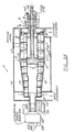
- FIGURE 1A a common sedimenting solid bowl centrifuge often known as a decanter centrifuge is shown at 10.
- Decanter centrifuge 10 includes a solid outer bowl 12 which terminates at a beach or cone area 14 on the right hand side thereof.
- Within bowl 12 is an inner hub carrying scroll conveyor 16.
- Bowl 12 and conveyor 16 rotate at different speeds so as to provide a differential, rotational movement to convey the settled solids.
- the settled higher density phase is moved along the channel 60a (FIGURE 3) formed by adjacent flights 60 in a general direction from the feed point to the small conical section of the bowl.
- An annular pool level 18 is also shown in FIGURE 1A.
- FIGURE 1B depicts a sedimenting-filtering screen bowl centrifuge 20.
- Screen bowl centrifuge 20 differs from solid bowl centrifuge 10 primarily in that the cone 14 terminates at a cylindrical screen region 21 which is perforated so as to emit liquid filtrate therethrough.
- FIGURE 1C depicts a filtering pusher centrifuge 22 which consists of a rotating bowl (comprised of two sections having differing diameters) 12 which has perforations 24 therethrough.
- an inner member shown schematically at 26 provides a periodic pushing function so as to push the solid phase cake through the rotating bowl 12.
- FIGURE 1D discloses yet another continuous feed centrifuge known as a scroll screen centrifuge 28.
- Scroll screen centrifuge 28 includes a conically shaped bowl 12 and a conically shaped worm conveyor 16, both of which rotate at different speeds so as to provide the differential movement described above. All of the aforementioned continuous feed centrifuges shown in FIGURES 1A-D are well-known to those skilled in the art; and all have in common a rotating bowl and an internal member (which may or may not rotate) and which conveys heavy phase materials relative to the interior of the bowl.
- continuous feed centrifuges of the type discussed above are provided with one or more sensors for the sensing of one or more parameters related to the operation of the centrifuge.
- a computerized control system which may be located at the centrifuge, near the centrifuge or at a remote location from the centrifuge is provided for interaction with the sensor or sensors in the centrifuge.
- This computer control system includes a controller which is typically a microprocessor controller and one or more control devices which are actuated in response to a command signal from the controller.
- the computer control system will actuate at least one of a plurality of control devices based on input from one or more monitoring sensors so as to provide real time continuous operational control.
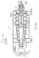
- FIGURE 2 a schematic is shown depicting examples of the monitoring sensors, control devices as well as components and features of the control system of this invention.
- FIGURE 2 more particularly shows a centrifuge 30 having associated therewith one or more internal sensors 32 and/or one or more external sensors 34.
- the centrifuge is associated with one or more internal control devices 36 and/or one or more external control devices 38.
- Both the sensors and the control devices communicate through an appropriate communications system 40 with a microprocessor controller 42 which, as mentioned, may be located on the centrifuge, near the centrifuge or at a remote location (such as a control room) away from the centrifuge.
- Microprocessor 42 has associated therewith a display 44 for displaying data and other parameters, a keyboard 46 for inputting control signals, data and the like, a memory or recorder 47 and a modem 48 for inputting and outputting data to the microprocessor 42 from a remote location.
- One or more power sources 49 provides power to computer 42 as well as the internal and external sensors and control devices.
- the microprocessor controller 42 receives a variety of inputs which have been categorized generally in terms of (1) information which is stored in memory when the centrifuge is produced, (2) information programmed at the site where the centrifuge is to be used, (3) operating parameters sensed by the external sensors 34, (4) input and output stream parameters sensed by the external sensors 34 and (5) internal centrifuge parameters sensed by the internal sensors 32.
- Examples of information originally stored in memory include information relating to the operation and maintenance of the centrifuge and training information, all of which will be readily available to an operator on video screen 44 associated with microprocessor controller 42.
- Examples of information programmed at the site where the centrifuge is to be used includes the operating ranges, output parameters desired feed properties and other site specific data such as relative humidity and other environmental factors.
- a large number of internal and external sensors 32, 34 which sense a variety of aspects related to the centrifuge, its operations and its input and output streams.
- the information or parameters sensed and/or measured by these sensors include operating parameters, input and output stream parameters and internal centrifuge parameters.
- Examples of the operating parameters which may be sensed by the external sensors 34 of this invention include acoustic emissions, vibration (including magnitude and frequency at both the gear box and bearings), torque (both ac and dc) and speed of rotation of both the bowl and conveyor as well as the differential speed.
- parameters sensed by external sensors 34 relating to the input and output streams include the solids concentration, the purity of recovery, the mass flow rate, temperature, constituent analysis (e.g., specific gravity), polymer and other chemical additions, particle size distribution, moisture of cake/density of cake and volumetric flow rate.
- the internal centrifuge parameters sensed using internal sensors 32 include the sensing of the height of the cake as it travels along the internal member within the centrifuge, the height of the interface including those situations where there are two or more liquid phases such as oil/water or emulsion phases, the height of the pool, the internal pressure within the bowl and gaps between structural elements housed within the bowl such as any gaps between, for example, the bowl and the worm conveyor. More specifically, such gaps include the cake baffle clearance from the bowl wall, the clearance between the bowl and the conveyor and the weir overflow.
- Still other parameters internally sensed in accordance with this invention include the temperature within the bowl and along the conveyor, the position of certain internal members such as the feed inlet and the scroll member, the cake and/or effluent surface velocity, solids concentration of the cake and/or the pool, particle size distribution within the bowl and the actual internal separation taking place which can be shown by an imaging sensor, e.g., shown visually by a camera or the like. It will be appreciated that the aforementioned internal and external centrifuge parameters sensed using the control system of the present invention will be more fully explained in detail hereinafter with regard to the several examples.
- the outputs from the microprocessor controller may be generally categorized as (1) data stored in memory 47 associated with the microprocessor controller 42, (2) operational control of the centrifuge and (3) real time information provided to the operator at the monitor 44 associated with the microprocessor 42.
- the computerized monitoring and control system of this invention may utilize the aforementioned sensors to monitor various parameters with respect to time and thereby provide a detailed historical record of the centrifuge operation.
- This record may be used by the microprocessor to model centrifuge operation, adjust models for centrifuge operation or generally learn how the centrifuge behaves in response to changes in various inputs.
- This record may also be used to provide a data log, provide preventative maintenance information, predict failure and predict machine wear.
- an important feature of this invention is that in response to the many parameters sensed by the sensors 32, 34 associated with the centrifuge 30, the operation of the centrifuge and thereby its ultimate efficiency and functioning can be adjusted, changed and preferably optimized.
- the microprocessor may actuate a number of internal and external control devices 36 and 38 to control a number of operations including, for example, adjustments to the speed of rotation, various baffle setting (e.g., cake baffle opening), flow rate of input stream, chemical additions such as polymer additions, differential speed, adjustment to absolute speed of bowl (as opposed to differential speed), temperature, pressure, pool heights, concentration of solids/liquids in the input stream (for example, the dilution of the feed slurry may be adjusted to reduce hindered settling), conveyance speed of cake, axial feed positions and axial conveyor positions.
- baffle setting e.g., cake baffle opening
- flow rate of input stream e.g., flow rate of input stream
- chemical additions such as polymer additions
- differential speed adjustment to
- control devices will be actuated if certain sensed parameters are outside the normal or preselected centrifuge operating range. This operating range may be programmed into the control system either prior to or during operation.
- This operational controls and examples of actual control devices which will provide such operational controls will be described in more detail hereinafter.
- SCADA Supervisory Control and Data Acquisition
- microprocessor devices convert plant measurement and status inputs into computer data for logging and transmission to higher level processors.
- supervisory controllers make strategic decisions for the operation of a process unit or plant and send out set points to dedicated controllers which will make the changes to actuators and ultimately the process.
- the SCADA network therefore connects to many controllers and field devices to gather information and make global decisions.
- Continuous feed centrifuges of the type discussed above in FIGURES 1A-D present extremely difficult problems with respect to the design and installation of sensors associated with the centrifuge, the acquisition of various measurements (particularly of parameters internal to the centrifuge), the ability to communicate data and power into and out from the centrifuge as well as the ability to provide control devices within the centrifuge and actuate those control devices in response to a command from a control computer.
- These difficulties arise from the fact that the continuous feed centrifuges of the type described herein include a bowl which rotates at an extremely high rate (e.g., 4000 or greater rpm) and typically include a conveyor which is also rotating at a high rate. The ability to deliver power and data to and from this rotating machine and provide appropriate functional sensor systems therefore represents extremely difficult challenges.
- FIGURE 1A the solid bowl centrifuge of FIGURE 1A is shown in greater detail and will now be briefly described.
- a decanter solid bowl centrifuge is shown at 10 and includes a housing or case 50.
- a solid bowl 52 which includes a cylindrical section 54 and a beach or conical section 56.
- an inner hub 58 carrying the worm conveyor 59 composed of a plurality of spiral conveyor blades 60.
- the hub 52 is driven by a motor (not shown) which is connected to a main drive connection or sheave 62.
- Sheave 62 is connected to bowl head flange 76 which in turn is connected to bowl 52.
- Bowl 52 and hub 58 are both connected through a differential speed gear box 64 such that the bowl and hub are rotated at high, slightly different angular speeds.
- a feed pipe 66 extends into the centrifuge through the main drive connection 62 and emits the feed (which is comprised of at least two phases such as a slurry (e.g., liquid and solid mixture)) near the center of the hub.
- Feed pipe 66 is passed through a conveyor trunnion (see FIGURE 4A) and is stationary relative to the rotating bowl and conveyor. The feed then enters a compartment formed inside the conveyor hub where it is accelerated to rotational speed before it discharges to the separation pool formed between the hub and inner surface of the bowl.
- the feed is subject to centrifugal forces, which accelerate the settling tendency of each phase with respect to the other phases.
- the heavy phase accumulates against the inner bowl wall.
- the heavy phase or sometimes solid sediment is pushed or scrolled to a cake discharge opening 70 at the smaller or conical end 56 of bowl 52.
- the cake discharge is known as the heavy phase output or discharge.
- the liquid or light phase output or discharge is driven to opposite end or cylindrical section 54 of bowl 52 and is discharged through the centrate discharge opening 72.
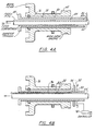
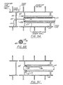
- FIGURES 4A through F are examples depicting a plurality of schemes for providing data and power access into and out from the interior of the centrifuge. All of FIGURES 4A through F are detailed enlargement views of that portion circled in FIGURE 3 and identified as FIGURE 4 details. That portion of FIGURE 3 identified by reference to FIGURE 5 details relates to FIGURES 5A-C which disclose examples of methods for routing wire or fiber optics through the feed pipe in order to gain a signal/power transmission path into the centrifuge.
- FIGURES 6A-K that portion of FIGURE 3 which is circled and identified as FIGURE 6 details are shown in FIGURES 6A-K and comprise examples showing a number of various internal sensors and measurement systems.
- FIGURE 7 Details corresponds to FIGURES 7A-J and describe examples for several control devices (actuators) for adjusting centrifuge operation in response to a command from the control computer.
- a bowl head 76 which attaches to bowl 52.
- Bowl head 76 has an axial opening 78.
- a conveyor trunnion 80 extends through opening 78 and includes a flange 82 which attaches to conveyor or hub 58.
- Conveyor trunnion 82 also includes an axial opening 84 and feed pipe 66 extends through opening 84 in a known fashion.
- one or more electrical cables or optical fibers 86 penetrates the stationary feed pipe 66 at a pressure tight fitting 88. This cable (which may be electrical wire or fiber optic) then travels through the interior of feed pipe 66 into the interior of the centrifuge and specifically into the center of hub 58.
- the fiber/cable 86 may be secured to an interior wall of the feed pipe and will run into the feed compartment for connection to sensors and the like.
- the FIGURE 4A communications scheme allows for the transmission of electrical signal and power as well as optical signal to be transmitted through the feed pipe and into the interior of the centrifuge.
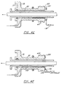
- FIGURE 4B depicts an alternative scheme to that shown in FIGURE 4A.
- electrical radio frequency (RF) transmission of signal and power is shown.
- RF radio frequency
- Such RF transmission is accomplished by use of an RF transmitter/receiver 90 which communicates with a stationary RF antenna 92.
- Stationary RF antenna 92 is spaced from and in communication with a rotating RF antenna 94 which is attached to a collar connected to the conveyor trunnion 80.
- Rotating RF antenna 94 is then hardwired using cable 96 in the annular space 84 to some point within the interior of the centrifuge for connection to a sensor or other device. It will be appreciated that data corresponding to parameters measured by internal sensors 32 will be transmitted through wire 96 to rotating antenna 94.
- This data will then be sensed by stationary RF antenna 92 and received by receiver 90. In turn, the data will then be sent to the controller 42. Alternatively, command signals and other information from the controller 42 may be sent to the RF transmitter 90 to stationary antenna 92 and then to rotating RF antenna 94. This data will then be transmitted along wiring 92 to a suitable control device 36 within the centrifuge. In addition to the transmission of signals and data, power may also be transmitted using the electrical RF transmission system shown in FIGURE 4B in a known manner.
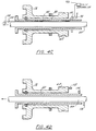
- FIGURE 4C depicts a scheme for the optical transmission of signals using the conveyor trunnion.
- stationary optical coupling and converter electronics 98 communicate with a rotating optical coupling 100 which has been mounted on rotating conveyor trunnion 80.
- rotating optical coupling 100 is hardwired via optical fibers 102 to some location or locations within the centrifuge.
- the optical fibers 102 will be connected to one or more sensors and/or one or more control devices.
- the fiber optic bundle 102 may be secured to the conveyor trunnion and connected to an optical coupling 104.
- an optical coupling 106 will be mounted on the conveyor hub and connected to a second fiber optic bundle 108.
- data from the control computer may be sent through the optical converter 97 to the stationary optical coupling 98 whereupon an optical signal will be transmitted to the rotating optical coupling 100.
- the signal received in rotating optical coupling 100 will then be transmitted to the fiber optic bundle 102 and on into the centrifuge to a sensor and/or a control device.
- information from an internal sensor will be transmitted along fiber optic bundle 102 to optical coupling 100 whereupon the signal will be transmitted to the stationary coupling 98, converter electronics 97 and then back to the computer 42 for processing.
- FIGURE 4D depicts an acoustic measurement or signal transmission scheme.
- known acoustic transducers are positioned at various locations in and along the centrifuge.
- acoustic transducer 112 is positioned adjacent the main drive sheave for picking up acoustic signals from the bowl while an acoustic transducer 114 is located adjacent the conveyor trunnion 80 for picking up signals associated with the conveyor 58.
- a third acoustic transducer 116 is located adjacent the feed pipe 66 for monitoring acoustical information related to the feed pipe.
- acoustic transducers 112, 114 and 116 may be used for signal transmission, that is, the transmission of data signals into and out from the centrifuge.
- the acoustic transducers may be used to obtain acoustic measurements of acoustical signals being generated by various components of the centrifuge. These acoustic signals or measurements may be used to evaluate and monitor different parameters of the centrifuge operation and processing.
- FIGURES 4A-C embodiments disclose several methods for transmitting data and power into and out from the conveyor
- FIGURES 4E and 4F depict several methods for conveying signals and power into and out from the interior of the bowl.
- FIGURE 4E a scheme for providing signal and power source transmission based on electrical RF or optical signals is shown.
- the element identified at 118 comprises any known RF transmitter/receiver or an optical converter.
- Element 118 is connected to a stationary RF antenna or optical coupling 120.
- stationary RF antenna or optical coupling 120 communicates with a rotating RF antenna or optical coupling 122 which is positioned on the rotating main drive sheave 62.
- An electrical wire or fiber optic bundle is connected to antenna/coupling 122 and travels along the interior surface of bowl head 76 within annular space 78.
- This wire/fiber optic bundle may be passed through an opening formed through head flange 77 where it will pass through several connectors and on into the bowl for connection to sensors and control devices.
- slip rings are used to transmit electrical signals and power into and out from the bowl.
- a rotating slip ring 124 is mounted on the outer flange surface of main drive sheave 62.
- a brush contact 126 is used to maintain continuous contact between rotating slip ring 124 and a signal converter, controller or other device 128.
- electrical wiring may be used to interconnect rotating slip ring 124 to sensors or control devices within the centrifuge.
- the wiring is located through the bowl head flange to another connector (not shown) for ease of assembly or disassembly. This other connector is located in the bowl and will transmit the data and/or power to sensors or control devices associated with the bowl.
- FIGURES 5A and B disclose details for the routing of wire or fiber optics through the feed pipe for use in the relevant communications schemes of FIGURE 4. Such routing preferably utilizes a rotary coupling or RF transmitter in the feed compartment.
- a rotary coupling or RF transmitter in the feed compartment.
- FIGURES 5A and B an electrical or optical rotary coupling is shown wherein a cable or fiber optic bundle 176 is secured to the inside of feed pipe 66.
- Feed pipe 66 includes a spider-like support centering clamp 178 (see FIGURE 5B) which includes a central opening 180 for receiving cable or fiber optic bundle 176. Cable 176 then travels through the feed compartment 68 and into a rotary coupling 182 which is secured to the feed target wall 184.
- spider support 178 aligns the cable/fiber optic bundle with rotary coupling 182 while allowing the passage of the feed slurry.
- a second cable/fiber optic bundle 185 is secured to the inner surface of hub 58 and is run along the length of the hub so as to mate with an appropriate sensor such as the video camera of FIGURE 6K, the light array sensor of FIGURE 6E or any of the other sensors described hereafter in FIGURE 6 which are mounted to hub 58 or one or more of the blades 60.
- FIGURE 5C depicts an electrical RF transmission scheme for signal and power through the feed pipe 66. In this scheme, an electrical wire 186 is secured to the interior of feed pipe 66 and terminates at one or more stationary RF antennas 188 which is positioned along the exterior of feed pipe 66.
- a rotating RF antenna is positioned on the surface of conveyor hub 58 and is spaced from but in communication with stationary RF antenna 188.
- a wire is then run from rotating RF antenna 190 to an appropriate sensor such as those described hereafter in FIGURES 6A through 6K which are located in the wall of hub 58 or one or more of conveyor blades 60.
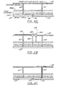
- FIGURES 6A-6K several examples of sensors for use in the computerized control or monitoring system of the present invention will now be discussed (however, it will be appreciated that FIGURE 4D depicted an acoustic sensor system which both acts as a communications link for signal transmission and also acts as a sensor system for sensing various acoustic activities in different portions of the centrifuge including, the bowl, the conveyor and the feed pipe).
- an ultrasonic sensor or transducer is shown at 136 having been mounted flush to the inside diameter of the wall of bowl 52.
- Ultrasonic transducer 136 is connected via a transmission wire 140 to microprocessor controller 42.
- Transducer 136 sends and received ultrasonic pulses into the space defined between hub 58 and the interior wall of bowl 52 and between various conveyor blades 60.
- the signals from transducer 136 will pass through the cake, the cake interface and into the pool as shown in FIGURE 6A.
- Transducer 136 will be able to therefore measure or sense pool height, cake interface, solids concentration in the cake and/or the pool (e.g., a solids concentration profile) as well as the conveyor blade tip clearance (that is the clearance between the tip of each blade 60 and the wall of bowl 52). This latter measurement may be made once per each differential revolution.
- transmission wire 140 may enter and exit the centrifuge using any of the relevant communication schemes shown in FIGURES 4A through 4F; and preferably, the communication and connection scheme of FIGURE 4F is utilized with the ultrasonic transducer of FIGURE 6A.
- FIGURE 6A depicts an ultrasonic sensor located in the bowl wall
- FIGURE 6B depicts an ultrasonic sensor which is positioned in the rotating conveyor 58. More particularly, first and second ultrasonic transducers 142, 144 are mounted to the conveyor hub outer wall 58. Transducer 142 is centrally mounted between a pair of blades 60 while transducer 144 is mounted closer to one of the blades. In addition, transducer 142 is mounted on an extension rod 146 so as to sense the interface between the cake and pool whereas transducer 144 is not mounted on an extension rod so as to be able to sense the height of the pool.
- Wires 148 interconnect transducers 142 and/or 144 to the exterior of the centrifuge using any of the suitable wiring schemes of FIGURES 4A and 4F.
- transducers 142, 144 run through the feed compartment 68 through a rotary coupling such as shown in detail in FIGURES 4A and FIGURE 5A.
- the ultrasonic transducers 142, 144 of FIGURE 6B can measure pool height and/or cake interface.
- any number of ultrasonic transducers may be mounted through hub outer wall 58 so that measurements along the entire length of the conveyor may be taken.
- any number of spaced ultrasonic transducers may also be mounted to the wall of the bowl so as to obtain information along the entire length of the centrifuge.
- a profile of, for example, solids concentration in the lighter and higher density phases may be obtained.
- a suitable ultrasonic sensor is disclosed in U.S. Patent 5,148,700.
- a suitable commercially available ultrasonic sensor is sold by Entech Design, Inc. of Denton, Texas under the trademark MAPS® .
- the sensor is operated at a multiplicity of frequencies and signal strengths.
- sensors operate to "see" the line of predetermined density in the plane of investigation.
- the ultrasonic signal is not returned by densities lighter than the predetermined density that lie above that line, and the signals do not penetrate to the greater densities that lie below the predetermined sludge density.
- the predetermined density to be investigated is also changed.
- the aforementioned ultrasonic technology can be logically extended to millimeter wave devices. Suitable millimeter wave radar techniques used in conjunction with the present invention are described in chapter 15 of Principles and Applications of Millimeter Wave Radar, edited by N.C. Currie and C.E. Brown, Artecn House, Norwood, MA 1987.
- FIGURE 6C depicts a pressure transducer for sensing pressure within the interior of the centrifuge.
- Pressure transducer may be mounted either in the bowl wall 52 and/or the pressure transducer may be mounted on or in or partially through a conveyor blade 60. Alternatively, the pressure transducer may be mounted through the hub 58.
- pressure transducer 150 is shown mounted in bowl wall 52 and pressure transducer 152 is shown mounted on conveyor blade 60.
- the wires leading from transducers 150, 152 may be interconnected to the exterior of the centrifuge using any applicable interconnection scheme described in FIGURES 4A through F.
- Pressure transducers 150, 152 may measure or sense the pressure or liquid head which must be compensated for G-force of the pool.
- FIGURES 6D-E depict an internal measurement sensor which utilizes a light array. More particularly, as best shown in FIGURE 6E, a light array sensor 154 is mounted to a conveyor blade 60 adjacent a light source 156. The light source 156 and the array of light sensors 154 are positioned along the radius of the blade 60. The light sensed will vary depending upon obstructions in the light path. Thus, as the pool height, cake interface or solids concentration varies, the light sensed by sensor 154 will similarly vary. The light emissions from sensor 154 of FIGURES 6D-E will measure pool height, cake interface and solids concentration.
- connection between the light sensor and the exterior of the centrifuge may be made by any of the suitable connecting schemes of FIGURES 4A through F with preferred connecting schemes utilizing FIGURES 4A-C or the scheme of FIGURE 5A.
- FIGURE 6F depicts an electronic level sensor shown generally at 158.
- Level sensor 158 mounts to conveyor blade 60 and may consist of any number of suitable electronic sensors.
- level probe 158 may be a conductive probe which changes resistance as pool height changes.
- level probe 158 may be a capacitance probe which is also responsive to pool height and cake interface.
- electronic level probe 158 will sense both pool height changes and cake interface changes.
- Level probe 158 will communicate to the exterior of the centrifuge using any of the relevant communications schemes in FIGURES 4A-F and particularly preferred communications schemes are those shown in FIGURES 4A, 4B and 5A.
- FIGURES 6G-H depict an acoustic array sensor 160 mounted on a conveyor blade 160 as best shown in FIGURE 6H.
- Acoustic array 160 may be excited so as to emit acoustic signals. These acoustic signals will produce changes in the acoustic response as the pool height and cake height vary. Thus, the acoustic array shown in FIGURES 6G-H will provide sensing and measurement of the pool height and cake height.
- Acoustic array 160 may communicate with the exterior of the centrifuge using any of the relevant communications schemes shown in FIGURES 4A-F and preferably will utilize the schemes of FIGURES 4A, 4B and 5A.
- FIGURE 6I depicts a temperature sensor which may be mounted to either the bowl, the conveyor or both.
- a temperature transducer or probe 162 is shown mounted flush to the inner diameter of bowl wall 52 while a temperature sensor 164 is mounted to a blade 160 of a conveyor.
- the temperature sensors may be positioned and located so as to measure the temperature of the pool liquid, and/or the cake, and/or the bowl wall, and/or the conveyor blade, and/or the hub.
- a large number of temperature transducers can be located within and along the length of the bowl wall and/or conveyor so as to provide a "real time" temperature record along the entire length of the centrifuge.
- FIGURE 6J depicts a baffle 166 which is located between a pair of adjacent conveyor blades 60.
- Baffle 166 is associated with a position transducer 168.
- Baffle 166 has several modes of operation. In a first mode of operation, baffle 166 is mounted between blade 60 so as to move radially from the rear outer wall of hub 58 towards the inner wall of bowl 52. As the baffle moves along the radial path, position transducer 168 will measure the linear motion of the baffle. In an alternative mounting scheme, baffle 166 is hinged along line 170 and position transducer 168 measures rotary motion of baffle 166.
- baffle 166 can take the form of an axial cake baffle or a cake restriction flow control wear plate, all of which are described in detail in U.S. Application Serial No. 08/468,205.
- the baffle 166 may be used to define conveyor position relative to the bowl wall.
- Position transducer (proximity sensor) 168 may utilize any of a number of known measurement technologies and can take the form of an ultrasonic distance transducer which is directly coupled during motion and converts to a digital signal via an encoder or may be directly coupled to motion for change relative to change in electrical properties such capacitance, inductance or resistance.
- position transducer and baffle 168, 166 may communicate (both for power and signal) to the exterior of the centrifuge using any of the communications schemes described above, particularly the schemes of FIGURES 4A and B.
- an internal sensor 32 used within the centrifuge comprises a sensor for imaging the interior of the centrifuge such as the video camera shown at 175 in FIGURE 6K.
- Video camera 175 may consist of any known miniaturized camera (such as a CCD camera) and may be located on the conveyor hub 58 or in another appropriate location such as the bowl wall or blade.
- the video camera 175 is preferably connected using the connection scheme of FIGURE 4A or 5A and the video camera may be used to detect pool surface flow phenomena, cake characteristics and other process activities within the centrifuge.
- a plurality of video cameras may be used throughout the interior of the centrifuge to provide the operator with a real time view of the entire centrifuge operation along the entire length of the centrifuge.
- the color sensor system described therein comprises a color video camera, a light source, a video-capture board, a computer, and a computer program that compares measured color vector angles to a previously stored calibration curve.
- Several cameras may be connected to a single color sensor computer or a single camera may simultaneously observe several locations using a network of fiber-optic cables.
- sensors used to sense internal centrifuge parameters such as acoustic, ultrasonic, radio frequency, microwave and laser based sensors can operate non-intrusively.
- non-intrusively it is meant that sensors can sense internal parameters from either the exterior of the centrifuge or, alternatively can sense parameters from the interior of the centrifuge but without having to physically enter the solid or liquid phases.
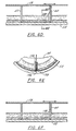
- FIGURES 7A-J five embodiments depicting internal control devices for controlling a centrifuge in response to control signals from a central computerized control system will now be described. These several embodiments provide an automatic adjustment mechanism for adjusting the pool height in response to control signals.
- a mechanical weir plate positioning system is disclosed.
- FIGURES 7A-B disclose the liquid phase discharge end of the centrifuge and for ease of understanding, the conveyor and trunnion are not shown.
- a weir plate 200 is transversely mounted to a positioning rod or sleeve 202 via a throw out bearing 204 and a connecting shaft 206.
- the throw out bearing 204 is attached to the centrifuge using a G-force counter balance spring 210. It will be appreciated that as the positioning rod 202 moves laterally to the left or the right, throw out bearing 204 will similarly be moved to the left and the right which in turn urges pivotally mounted shaft 208 to cause weir plate 200 to slide radially outward or inward. As weir plate 208 slides inward toward the axis of the machine, the pool radius is decreased. In contrast, as the weir plate 200 moves radially outward (in response to positioning rod 202 moving to the left) the pool radius increases and the pool height or depth decreases. The counter balance spring will aid in urging the throw out bearing to move to the left, that is, to position the weir plate. Thus, axial movement of the positioning rod will cause axial movement of throw out bearing 208 which in turn will change the location of weir plate 200 and adjust the pool height or depth.
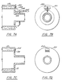
- FIGURES 7C-D similarly provide a means for controlling of the radial position of effluent weir 72.
- a metal lip 212 is positioned over the effluent opening or port 72.
- Metal lip 212 is comprised of any known material which undergoes straightening or bending at crease 214 in response to varying temperature.
- the distance from the machine axis of rotation to the metal lip increases. This is commonly known as the pool radius.
- the pool radius As the pool radius increases, the pool depth or height decreases.
- the thermal energy to open or close metal lip 212 may be provided by any suitable source including radiant energy or electrical resistance heating.
- the electrical energy for actuating metal lip 212 may be provided by any suitable connection scheme such as, for example, the connection scheme of FIGURE 4F.
- FIGURES 7C-D thus represent an example of a thermally activated weir plate for controlling the size of effluent port 72.
- FIGURES 7E-F disclose an air jet restriction system for regulating the height of the pool.
- a stationary air scoop 216 is attached to casing 50 so as to discharge in the vicinity of the rotating effluent port 72.
- air flow is directed radially about the weir such that it is directed by the air scoop 216 at effluent port 72. The effect is that the air stream will impede liquid flow over the weir.
- the air stream may be provided by circulating air within the case as shown in FIGURE 7F or by some external source.
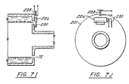
- FIGURES 7G-H disclose a pool height adjustment mechanism comprising an inflatable weir.
- an inflatable bladder which may be inflated by air or other suitable fluid
- Bladder 218 is connected by a fluid tight conduit 220 to a rotary fluid seal 222 which in turn is connected by another conduit 224 to a suitable pressurized fluid (such as pressurized air).
- a suitable pressurized fluid such as pressurized air
- FIGURES 7I-J disclose an electromagnetic force weir adjustment system for adjusting the pool height.
- a movable weir plate 226 similar to the movable weir plate 200 in FIGURE 7A is mounted to slidably and radially move along weir plate 201 to thereby increase or decrease the pool radius. Movable weir plate 226 will slide in one or the other direction in response to an adjustable magnetic field emitted by coil 228.
- a counter G-force spring and damper system 230 is connected to the end of movable weir plate 226 which is opposite to the adjustable magnetic field coil 228.
- the weir plate may be mechanically "tuned” to minimize pulsing effects generated by the intermittent magnetic force on the movable weir plate 226 as a result of rotating past the coil.
- precise movement of the movable weir plate 226 may be achieved thereby decreasing or increasing the size of the pool radius which in turn will raise or lower the height of the pool.
- FIGURE 7K depicts internal pressure sensor and control systems. It will be appreciated that sensing pressure internal of the case 50 will provide a reading of internal bowl pressure since the bowl interior is open at the liquid and solid discharge phase ports.
- a pressure sensor 300 senses case pressure and a case pressure control valve 302 is connected to a case pressure control gas supply 304.
- pressure sensed by sensor 300 is monitored by computer 42.
- computer 42 in turn can transmit control signals to control valve 302 to raise or lower the pressure within the case 50.
- internal pressure may also be controlled by monitoring pressure at the feed pipe 66 using pressure sensor 306 and pressure control valve 308, both of which communicate with computer 42.
- the gas supply 310 supplies the pressurizing gas directly into the feed compartment 68.
- FIGURES 3A-D show respectively external sensors and sensor systems for sensing vibration at the gear box and bearings (FIGURE 3A), torque (both AC and DC) (FIGURE 3B) and rotational speed of conveyor and bowl (FIGURE 3C).
- vibration may be sensed at the bearings by using a vibration sensor 312 positioned on the upper bearing housing and/or a vibration sensor 314 positioned on the base 316 of the bearing housing.
- vibrations at the gear box may be sensed using a vibration sensor 318 associated with the gear box 64.
- the vibration sensors 312, 314 and 318 can measure vertical, axial or transfers vibrations.
- vibration measurements on the input pinion shaft 320 are currently used for control checking on conventional centrifuges. While vibration sensors have not been mounted on pinions 320 during plant operation, in accordance with the present invention, a vibration sensor 322 may be mounted to the pinion shaft 320 for use during operation.
- FIGURE 3B sensors for measuring torque are depicted. More particularly, shaft 320 extending from gear box 64 is connected to a torque transducer 323 which communicates by signal wires 324 to a torque transmitter 326.
- the input pinion 320 is fixed at the torque transducer 323. If however, the pinion is attached to a hydraulic or electric motor, a break or some other device, then the torque may be measured using the signal derived from the driver.
- pressure of the hydraulic fluid is proportional to torque and therefor torque may be derived by measuring the hydraulic fluid pressure.
- the current is proportional to the torque and therefore torque is derived using this known mathematical relationship.
- the chatter or AC torque may be available at the torque transmitter 326.
- FIGURES 3C-D depict sensors for measuring rotational speed.
- a known tooth speed pick up sprocket 328 is mounted on the pinion input shaft 320 to gear box 64 and the gear box casing as shown in FIGURE 3C.
- a speed pick up or proximity sensor 330 sends electrical pulses to a rate calculator 332 using information derived from these sensors.
- a differential speed and location of speed may be calculated in a known manner.
- sensors are used to sense or monitor parameters in all three streams, namely the input stream, the higher density output stream and the lighter density output stream. Control of the centrifuge is then achieved based, at least in part, on these three sensed parameters.
- parameters which may be sensed in all three streams include solids content (such as percent solids), volume flow rate, mass flow rate, particle size distribution, temperature, constituent analysis and polymer addition.
- LIBS sensor laser-induced breakdown spectroscopy sensor
- LIBS sensors are particularly useful in the determination of elemental composition in situ , that is, without the need for removal of a sample for analysis at a separate location.
- the LIBS sensor allows fast, discrete or continuous, real-time analysis.
- An LIBS-type sensor suitable for use with the present invention is described in U.S. Patent No. 5,379,103 to Zigler. Such sensors are capable of measuring the percent concentration of one or more elements in a mixture.
- Control of external operations of the centrifuge present less difficult challenges than the control of internal components such as baffle settings, feed and conveyor position and pool height.
- rotational and differential speed adjustments are easily made to the driving motor or motors.
- Flow rates, chemical additions solid/liquid concentrations and temperature adjustments are all made by adjusting the feed input in conventional manners.
- the memory/recorder 47 receives operating data pertinent to centrifuge operation from controller 42. This information is used to improve the process performance and maintenance requirements of the centrifuge. At any time, such operating data may be retrieved from a position local to the centrifuge or remotely. The data may be displayed in real time, i.e., while the centrifuge is operating using monitor 44, or as a historical record of some prior operating sequence.
- Data logging is an important historical record which can be obtained from the present invention.
- Data logs may be made on a number of variables. Some of these variables include, bowl speed, differential speed, torque, main drive motor amps and an operator supplied signal for feed flow.
- Controller 42 preferably communicates through standard communication cards used on PC equipment. As such, Ethernet, RS-232 and modem capabilities exist for the operator's use. Therefore, the present invention allows the plant to collect centrifuge operating data through a plant wide Ethernet or other network. Additionally, the present invention may communicate to other process devices not supplied by the centrifuge manufacturer. In this way, the operator uses the control and monitoring system of this invention to gather information on a larger portion of the process.
- the operator may monitor the centrifuge's real time performance and historical log. Suitable software for this activity includes operator screens for data display, message displays for operating assistance and may include an on-line operation and maintenance manual. The operator may also control and optimize the performance of the centrifuge through the plant network.
- Pre-formatted reports may present the retrieved data to show information such as; operating hours, alarms generated, number of starts, number of trips, electrical power used, maximum and minimum values for measured variables, total feed processed, etc.
- the centrifuge manufacturer may recommend measures to avoid down time and to optimize run time.
- maintenance procedures may be suggested based on the operating log of elapsed run time, and unusual operating conditions such as high bearing temperatures or frequent high torque trips.
- the operating data log thus helps to trouble shoot various operating conditions of the centrifuge. This enhances the centrifuge manufacturer's ability to solve customer operational problems and to keep equipment on line.
- Controller 42 may operate and process using any one or more of a plurality of schemes including “feed forward”, “feedback”, “genetic algorithms” and “expert” systems.
- Feed forward is where process and machine measurements (or calculated, inferred, modeled variables normally considered ahead of the centrifuge in the process) are used in the controller 42 and or control scheme to effectively control the operation of the centrifuge.
- Control of the centrifuge encompasses both physical and mechanical aspects and operating ranges dealing with safe operation as well as efficient operation regarding both mechanical and process as well as optimum performance of the operation.
- Feed forward schemes inherently acknowledge that the conditions and state of the feed material to the centrifuge change over time and that by sensing or calculating these changes before they enter the centrifuge, control schemes can be more effective than otherwise might be possible.
- Feedback is where measurements and calculated values that indicate process performance and machine state are used by controller 42 and the control scheme contained therein to stabilize the performance and to optimize performance as feed conditions changes and machine performance changes in reference to set points and optimization objectives, process and machine models are embedded in controller 42 as well as methods to evaluate the models to determine the present and future optimum operating conditions for the machine.
- Optimum conditions are specified by flexible objective functions that are entered into the controller 42 by the operators or plant control system that is dealing with plant-wide control and optimization.
- the models contained therein are adaptive in that their form or mathematical representation can change as well as the parameters concerned with any given model. These models include, but are not limited to first principles and phenomenological models as well as all classes of empirical models that include neural network representations and other state space approaches.
- Optimization is accomplished by combining the knowledge contained about the process and machine through these models with expert system rules about the same.
- These rules embody operational facts and heuristic knowledge about the centrifuge and the process streams being processed.
- the rule system can embody both crisp and fuzzy representations and combine all feed forward, feedback and model representations of the machine and process to maintain stable, safe operation and also optimal operation including the machine and the process. Determination of the optimum operating states includes evaluating the model representation of the machine and process. This is done by combination of the expert system rules and models in conjunction with the objective functions. Genetic algorithms and other optimization methods are used to evaluate the models to determine the best possible operating conditions at any point in time.
- Economic performance includes base machine operating costs, the normalized performance cost dealing with throughput rates and the quality of the products produced both in absolute terms and terms normalized for feed conditions.
- FIGURE 2 reflects the "intelligent" controller features including calculation of sensor values, a rule module, a model module and an optimization module.
- the adaptive control system of this invention uses one or a combination of internal and/or external machine and/or process variables to characterize or control the performance of the centrifuge, in terms of the desired process outputs.
- the control system continually updates its knowledge of the process, so that its control performance improves over time.
- Table provides an overview of certain process variables to be sensed using the aforementioned sensors, control modes and variables which are then controlled by computerized controller 42 for optimizing and/or adjusting the performance of a continuous feed centrifuge.
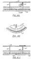
- FIGURE 8 is a schematic view of a continuous feed solid bowl (FIGURE 1A) centrifuge depicting the feed stream, liquid effluent or centrate stream and solid (cake) stream.
- the mass rate M i and/or volumetric flow rate Q i of the liquid and solid phase input/output stream "i" may be measured in real time using an appropriate measurement device as described above. These measurements are then used to adjust the mass rate and/or flow rate of the input stream so as to optimize centrifuge operation.
- An alternative to using weight fraction W i is to use volume fraction of solids ⁇ i as shown in brackets in FIGURE 8 in conjunction with volumetric flow rate Q i in place of mass rate M i .
- FIGURE 9 a plot of material balance indices with time is shown. Variation of such material balance indices with time provides an indication of the state and steadiness of the separation process within the centrifuge.
- the mass rate for the solid and liquid phase output and feed is measured in real time using appropriate external sensors as is the weight percent of solids W i in these three streams.
- This information is sent to the computerized controller where a steady state check is made over a time period such as illustrated by FIGURE 9, and the control computer can then signal the various measuring sensors as to the state the machine is operating at (steady versus transient), and whether control of the machine should be taken place accordingly.
- a preferred processing technique involves the following:
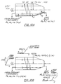
- FIGURE 10A is a schematic of a solid bowl centrifuge of the type disclosed in aforementioned U.S. Application Serial No. 08/468,205. It will be appreciated that in accordance with this invention, many of the operating variables and parameters in FIGURE 10 may be measured using various external sensors and may thereafter be controlled in order to optimize operation. Such operating parameters include polymer dosage D, pool depth h p , cake height h, gap of beach control structure or cake baffle h g , angular speed ⁇ , dc and ac torque (T and T') and power input P. Temperature can be a particularly important parameter for measurement and control as temperature effects viscosity, surface tension and wetting angle of the liquid phase.
- FIGURE 10B depicts the operating parameters and graphical relationship for classifying particle size distribution, measured by % cumulative under a given size, or F(d) for the feed, liquid effluent and cake solids.
- the variables shown in FIGURE 10B are sensed or measured in real time, and input to the computerized control to determine particle size distribution and improve so-called clarification of the effluent liquid stream.
- improved clarification is achieved through the computer control of one or more variables such as polymer dosage, bowl angular rotation speed, differential speed or pool height.
- the machine is tuned to operate such that 90-95% of the particles is less than a prescribed size (1-2 microns).
- the oversize particles greater than 2 microns settle in the machine as rejected cake.
- the undersize particles less than 0.5 micron are separated out as slime downstream.
- the present invention may be used to control feed dilution (fine particles where polymer addition is not practical). Settling of a particle can be interfered with by the presence of neighboring particles' flow fields. At “high" solids concentration, the solids within the slurry settle at the same velocity (hindered settling) independent of size and depends only on concentration. As shown in FIGURE 11, in accordance with the present invention, measurement and control of volume fraction of feed solids using the computerized control system of this invention can achieve optimization.
- FIGURE 12 is a graph describing optimization of solids separation through the centrifuge.
- the computer controller can determine ( ⁇ f ) max, which gives the maximum flux, and thereby optimizes solids throughput.
- FIGURE 13 depicts control of feed dilution using recycled centrate (liquid phase discharge).
- real time measurements are made of Q e , ⁇ e , ⁇ , Q f , ⁇ f , Q' f , ⁇ ' f and ⁇ s .
- the computerized controller will alter (e.g., increase or decrease) the recycle ratio ⁇ in an effort, for example, to obtain cleaner effluent or better solids recovery by manipulating the operating point on the solid flux curve.
- FIGURES 14A-C show the graphical constraints for optimizing polymer dosing.
- the effluent solid concentration W e and cake solid concentration W s are sensed. This information is then used by the controller to control the dosing by increasing or decreasing the polymer volumetric flow rate and/or polymer concentration.
- FIGURE 15 depicts a cake baffle of the type disclosed in the aforementioned U.S. Application Serial No. 08/468,205.
- the cake baffle functions to preclude fine solids from being removed with the cake and also assists in the conveyance of the cake by buoyance force as the pool is set at a level close to the spill of the conical beach.
- this information may be used by the computerized control system to control the opening of the cake baffle and thereby optimize the classification of solid particle size in the cake with respect to quality and throughput. Variation in rheological properties of the cake (watery versus granular, non-Newtonian behavior such as shear thickening versus shear thinning) can thus be accommodated.
- FIGURE 16 graphically depicts process controls for controlling (e.g., removing) foreign or oversized particles (grit-particles above 15 microns as shown in Fig. 16) in order to produce a purified, fine slurry.
- process controls for controlling (e.g., removing) foreign or oversized particles (grit-particles above 15 microns as shown in Fig. 16) in order to produce a purified, fine slurry.
- this information may be used by the computerized control system to control the rate and rotational speed of the centrifuge and thereby increase the purity of the fine product slurry.
- Thickening of fluid streams can be important in waste treatment and food processing. Thickening is used to remove bulk liquid and prepare for final dewatering, and recover valuable liquid from slurry and concentrating feed streams. Referring to FIGURE 17,
- this information may be used by the computerized control system to control the rate, rotational speed, differential speed and polymer dosage (if it is used in the application) and thereby concentrate or thicken the solid phase output stream (cake).
- FIGURES 18A-C thus depict various parameters which may be sensed with the resultant measurements used by the computerized controller to control the degree of liquid drainage from cake (e.g., dewatering).
- cake solids are sensed and measured; and this information is used by the control system of this invention to control pool setting, rotational speed and differential speed.
- FIG. 18B cake solids are sensed and measured; and this information is used by the control system of this invention to control the feed rate.
- torque mean and fluctuating components
- this information is used by the control system of this invention to control feed rate, pool setting, rotational speed and differential speed.
- the mean conveyance torque can also be measured and that information either alone, or combined with the chatter torque may be used to control the centrifuge.
- FIGURE 19 a graphical illustration is shown of the combined effects of chatter torque and conveyance torque.
- this information may be used by the computerized control system to control differential speed, feed rate, G-force, (rotational speed) and thereby optimize machine performance.
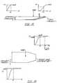
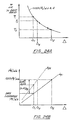
- FIGURE 20 the liquid drainage path is blocked at higher rates as cake wets adjacent blades. At lower rates, the cake does not fully wet the helix channel and the drainage path for expressed liquid is fully open. The net effect is shown in the so-called hockey-stick profile of FIGURE 21. It is typical for non-compactible but drainable cake with granular structure. Based on the foregoing, cake moisture (or dryness) can be controlled by measuring cake moisture external and in-situ and cake profile in-situ and in response to the resultant information, controlling differential speed to open up the drainage.
- Dewatering of compactible, non-drainable, fully saturated cake may be controlled and/or optimized by (1) sensing and controlling pool height, (2) sensing and controlling cake baffle opening h g , (3) sensing and controlling G, (4) sensing and controlling cake height, (5) sensing and controlling feed rate and feed solids,(6) sensing and controlling polymer dosing, (7) sensing and controlling cake solids, and (8) sensing and controlling effluent solids.
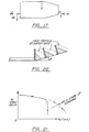
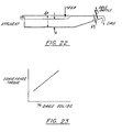
- FIGURE 22 depicts an application of the foregoing for biological sludge (e.g., sewage). By controlling these parameters, the machine can be operated under suitable conditions despite the deep cake blanket and minimal pool volume for clarification.
- biological sludge e.g., sewage
- FIGURE 23 shows the relationship between average torque as measured as a function of % cake solids for compactible cake.
- average torque may be measured and this information is an indication of the cake depth inside the bowl. It may then be used by the computerized control system of this invention to control and/or optimize % cake solids.
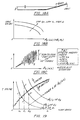
- FIGURE 24A depicts the inverse relationship between (mean) conveyance torque and differential speed in a solid bowl centrifuge.
- FIGURE 24B depicts the relationship between mass rate of the feed and cake solid, differential speed and baffle opening in solid bowl centrifuge. Based on FIGURES 24A-B, in accordance with the present invention, by sensing torque, (an indication of cake solids) and effluent, this information may be used to control the baffle opening and differential speed so as to control the operation of a solid bowl centrifuge, otherwise cake solids or effluent quality is compromised.
- Cake height distribution in a solid bowl centrifuge provides information on (1) cake dryness within the centrifuge and discharged cake, (2) torque, (3) conveyance, (4) solids content in centrate, (5) utilization of centrifuge volume/space for clarification, compaction and dewatering and (6) potential problems related to solids conveyance.
- the computer system of this invention may control feed rate, rotational speed, differential speed, and pool and cake baffle opening (when present). The ability of the cake to flow is dependent upon these aforementioned variables. Referring to FIGURE 25, various scenarios are shown for increasing feed rates and controlling the cake baffle or exit gate opening in response to cake height sensing, all of which have a predetermined effect on cake flow.
- FIGURE 26 depicts a 3-phase oil/water/solid slurry where the water is to be separated from the oil.
- Rw water discharge radius
- Ro oil discharge radius
- Ri oil-water interface radius.
- FIGURE 26A provides a working chart to determine the position of the interface radius once the radii of discharge of both the heavy and light phase are prescribed and the densities are known. By controlling the discharge radii of the light and heavy phases, the degree of purification of the light phase or the degree of concentrating the heavy phase can be controlled.
- filtrate solids may be controlled using recycle of a controlled amount of such solids back to the feed stream. This is accomplished by measuring the filtrate solids and using that information to control the degree of recycling. Also, in a screen bowl centrifuge, the pool should be maintained close to the junction between the beach and cylinder to avoid an overly deep pool which spills over to the screen. This is accomplished by sensing the pool height and then using this information in the computerized control system of this invention to control the height of the pool at the junction.
- This example relates specifically to a pusher type continuous feed centrifuge.
- cake solids may be optimized through control of volumetric flow rate. Also, by sensing the cake height and cake dryness (at discharge and along the basket in-situ), the stroke length as well as the stroke frequency can be adjusted while the machine is running or at idle to yield optimal cake dryness and capacity.
- This example relates specifically to a screen scroll continuous feed centrifuge as schematically shown in FIGURE 30.
- information regarding the cake height and dryness along circumferential and longitudinal directions of the basket is used by the computerized control system of this invention to control differential speed between the scroll and screen as well as the feed rate while the machine is running or at idle.
- This example relates specifically to a vibratory screen centrifuge where the solids under vibration generated inertia are conveyed down the screen.
- the included angle of the screen is wider so that a component of the centrifugal force propels the solids down the screen toward the larger diameter overcoming the frictional resistance.
- This is similar to FIGURE 30 but without the scroll.
- the amount of vibration is tuned to give optimal capacity and cake dryness.
Description
- This invention relates generally to continuous feed centrifuges. More particularly, this invention relates to methods and apparatus for automatically monitoring, operating and controlling continuous feed centrifuges using computer control systems and remote sensing devices. This invention is particularly useful in the control and operation of decanter centrifuges such as solid bowl and screen bowl centrifuges, but also finds utility in other continuous feed centrifuges such as pusher and scroll/screen centrifuges.
- Continuous feed centrifuges are used in many industrial applications for separation of solids and liquids. In general, such continuous feed centrifuges include an outer rotating member in the form of a solid or perforate bowl. Examples of continuous feed centrifuges are disclosed in commonly assigned U.S. Patent Nos. 4,381,849; 4,464,162; 5,147,277 and 5,378,364. As used herein, continuous feed centrifuges include sedimenting solid bowl and filtering pusher and scroll/screen as well as hybrid sedimenting and filtering screen bowl centrifuges. For ease of illustration, the present invention will be primarily described from the standpoint of a solid bowl centrifuge and therefore the components and operation of prior art solid bowl centrifuges will now be described in some detail.
- A solid bowl or decanter centrifuge generally includes an outer bowl, an inner hub carrying a scroll conveyor, a feed compartment within the conveyor wherein the feed slurry is accelerated to speed before being introduced into the separation pool, and discharge ports for cake solids and clarified liquid or centrate. It will be appreciated that the cake solids will be interchangeably referred to herein as solid, heavy phase or higher density discharge or output stream. Similarly, the clarified liquid or centrate will be interchangeably referred to herein as liquid, light phase or lower density discharge or output stream. The bowl includes a cylindrical section and a conical beach section. The bowl and the hub are rotated at high, angular speeds so that heavier solid particles of a slurry, after accelerated to speed and introduced into the bowl, are forced by centrifugation into an annular layer along the inside bowl surface thereof. By differential rotation of the scroll conveyor and the bowl, the sediment is conveyed or scrolled to a cake discharge opening at the smaller, conical end of the bowl. Additional discharge openings are provided in the bowl, usually at an end opposite of the conical section for discharging a liquid phase or liquid phases separated from the solid particles in the centrifuge apparatus.
- Controlling and optimizing the operation of such centrifuges is a difficult task considering the high rotational speeds of the bowl and hub, and the continuously changing characteristics of the input or feed stream (slurry) and the light phase and heavy phase output streams. Notwithstanding these difficulties, there have been some attempts in the prior art to provide control systems for bowl/conveyor type (decanter) centrifuges.
- EP 0 490 270 A2 discloses a method of controlling the rotation of a centrifuge including an outer bowl shell and a scroll supported in the outer bowl shell for rotation relative to the outer bowl shell. The method according to EP 0 490 270 A2 includes the steps of obtaining control signals representing forces acting on the scroll and controlling the rotation of the centrifuge as a function of the control signals. The method further comprises the steps of measuring an axial force imparted on the scroll parallel to an axis of rotation of the scroll, generating feedback signals from values obtained from the measuring step, and controlling the rotation of the centrifuge as a function of the feedback signals.
- From JP-A-58-205 554 a sludge concentrating device is known, in which sludge concentrating device the concentration of sludge in the liquid formed under various disturbing factors is measured exactly. Based upon this measurement the operating conditions of a decanter-type centrifugal concentrator are controlled in such a way that the sludge concentration in the sludge disposal stage is maintained as uniformly as possible.
- US 4,070,290 discloses a solids-liquid separating centrifuge with bowl and conveyor members rotated about a common axis at a differential speed. Said solids-liquid separating centrifuge has means for sensing torsional vibration of at least one of the members about its axis and providing an output representative of the vibration amplitude, and signal means which provides an indicative signal when the output indicates vibration amplitude above a predetermined level. The indicative signal may operate an alarm, or an automated centrifuge throughput reducing system, or both.
- JP-A-62-168 560 discloses a method for controlling concentration in a centrifugal concentrator. The concentration of the concentrate discharged from the centrifugal concentrator is detected by a detector and the detection signal thereof is input to a comparing operator. As the objective concentration of the concentrate is imparted to the comparing operator through a setting device as a set value, both of them are compared to calculate deviation and, if there is deviation, at least one of the flow amount of the stock liquid and that of the separated liquid is adjusted through a controller so as to eliminate said deviation. Thereby the speed of the pump of a stock liquid supply apparatus is adjusted on the basis of the flow amount of the stock liquid and the opening degree of the valve of a separated liquid flow amount regulator is adjusted on the basis of the flow amount of the separated liquid.
- DE 39 21 327 A1 discloses an apparatus for controlling the level of liquid in a centrifugal separator drum by regulating the flow of liquid out of the drum. The drum includes a plurality of circumferentially spaced openings and a radial end wall of the drum. The openings have movable weir plates in one form controlling the openings with the weir plates movable and positionable in a radial direction by axially movable linkage. In another form, a conduit passage leads from an end opening. By controlling the flow through the openings in the end wall, the liquid level is functionally controlled within the drum. The control mechanisms are situated externally of the drum for ease of repair and to provide control which can be continually monitored.
- US-4,369,915 discloses a method and apparatus for regulating the differential rpm of two rotating parts, such as the external drum and internal worm conveyor of a worm centrifuge by means of undertaking an electronic measurement and sampling of the rotational speed during the course of operation of a particular device under speeds of each part and supplying this information to a microprocessor which evaluates the respective rotational speeds of the parts and relays a signal to the drive device for one of the parts in order to maintain a preselected rpm differential between the rotational speeds of the two parts. Different characteristic curves are stored in the microprocessor for optimum rpm differential during the course of operation of a particular device under different conditions, such as for different sludge consistencies in the case of use with a centrifuge. If deviation of the actual rotational speed of one of the parts from the optimum value is detected, the microprocessor operates to return operation to the optimum values.
- JP-A-02-071 859 discloses a method for regulating the water level of liquids separated from a centrifugal dehydrator. According to JP-A-02-071 859 an inner drum with a screw conveyor equipped to the outer periphery thereof is provided on the inside of an outer drum and both the inner and outer drums are rotated while holding several velocity difference and thereby sludge supplied to the space between both the inner and outer drums is separated into solid and liquid. Both the inner and outer drums are rotatably supported by a fixed shaft and a hollow hole for discharging separated liquid is provided at one end part of the shaft. At least one piece of skimming pipe communicated with the hollow hole is provided in the radial direction at one end part of this hollow hole and also a discharge valve is provided at the other end part thereof. Water pressure of separated liquid in the outer drum is sensed with a pressure sensor and the discharge valve is opened and closed so that the sensed pressure is made constant. Separated liquid is collected through a pipe while holding the water level of separated liquid constant and discharged through the discharge valve via the hollow hole.
- A full jacket-worm centrifuge for continuous separation of water-sludge mixtures is disclosed in US 4,303,192. The centrifuge according to US 4,303,192 has a cylindrical drum jacket with a conically tapered portion in a direction of a solid matter discharge. A worm conveyor having cylindrical and conical portions is arranged within the drum jacket. Between a slurry inlet on the drum jacket and the solid matter discharge a liquid separation product discharge is arranged. Between this liquid discharge and the solid matter discharge a cross-sectional constriction is provided having a plate extending radially to a point spaced from an interior side of the drum jacket. Means are provided to control a differential speed between the drum jacket and worm conveyor or solid matter quantity supplied per unit of time to the centrifuge according to torque of the worm conveyor, solid matter concentration in the solid matter discharge, or solid matter concentration in the liquid separation product discharge.
- For the most part, all of these control systems utilize torque measurement (e.g., dc or steady torque measurement) as an input for controlling the speed of the conveyor and/or bowl. Examples include U.S. Patent Nos. 4,369,915; 4,432,747 and 4,668,213. All of these patents disclose a torque measuring device for measuring the torque input to the screw conveyor and based on this torque measurement, the differential speed between the bowl and conveyor is optimized. In Patent 5,156,751 to Miller, a similar type of centrifuge is shown wherein sensing and control means 33 regulates the speed of the
conveyor 22, the control means being responsive to a torque measurement. - U.S. Patent 4,303,192 ('192) to Katsume discloses a centrifuge control system which controls and/or regulates the differential speed between the bowl and the conveyor and/or the solid matter quantity supplied to the centrifuge per unit of time in response to the sensing of certain operating parameters such as (1) the torque of the conveyor and/or (2) solid matter concentration in the solid matter discharge and/or (3) solid matter concentration in the liquid separation product discharge. The '192 patent discloses a measuring unit 43 for measurement of torque, a solid matter
concentration measuring unit 40 for measurement of the centrifuge solids discharge and a solid matterconcentration measuring unit 38 for measurement of solids concentration in the liquid discharge. Measuringunit 40 determines the quantity and/or the solid matter concentrations of the concentrated sludge being output and converts the resulting value into an electrical signal. Similarly, the solid matter concentration in the liquid separation product is determined by measuringunit 38, converted to an electrical signal and transmitted tocomputational unit 42, 48. As stated incolumn 6 of the '192 patent, lines 24-33, the control system has three input variables including (1) torque of the conveyor, (2) quantity and concentration of solid matter in the solids discharge and (3) quantity and concentration of solid matter in the liquid separation product. Based on this input, three controls of the centrifuge are initiated including (1) the speed of the bowl, (2) the differential speed of the bowl and conveyor and (3) the amount of solid matter/slurry quantity being supplied to the centrifuge. - Other decanter centrifuge patents describing control systems include patents 5,203,762 ('762) and 4,298,162 ('162). The '162 patent describes a control system for controlling the drive motors of the centrifuge using several ac/dc conversions for generating power from the backdrive motor and converting this power for use by the main drive motor. The '162 patent utilizes a gear which interconnects the screw conveyor to the bowl and two rotary, positive displacement machines for controlling relative rpm of the conveyor.
- Unfortunately, none of the aforementioned prior art provides a comprehensive computerized (e.g., microprocessor) control system for operating, controlling and monitoring continuous feed centrifuges such as solid bowl, screen bowl, scroll/screen or pusher type centrifuges. However, the ability to provide precise, real time control and monitoring of such centrifuges constitutes an on-going, critical industrial need.
- Therefore it is an object of the invention to provide "intelligent" systems and methods for operating, controlling, monitoring and diagnosing various parameters and processes of continuous feed centrifuges. "Intelligent" here means that such a system has the capability of providing information about itself, predicting its own future state, adapting and changing over time as feed and machine conditions change, knowing about its own performance and changing its mode of operation to improve its performance.
- This object is achieved by continuous feed centrifuges according to
claims - Advantageous and preferred embodiments of the continuous feed centrifuge according to
claim 1 are subject matter ofclaims 2 to 6. Advantageous and preferred embodiments of the apparatus according to claim 9 are subject matter ofclaims 10 to 13. An advantageous and preferred embodiment of the continuous feed centrifuge according toclaim 15 is subject matter ofclaim 16. Advantageous and preferred embodiments of the continuous feed centrifuge according to claim 17 are subject matter ofclaims 18 and 19. - Referring now to the drawings wherein like elements are numbered alike in the several FIGURES:
- FIGURES 1A-D are schematic sectional views of continuous feed centrifuges, respectively, solid bowl, screen bowl, pusher and scroll/screen centrifuges used in the monitoring and control system of the present invention;
- FIGURE 2 is a schematic view of the monitoring and control system for continuous feed centrifuges in accordance with the present invention;
- FIGURE 3 is a cross-sectional elevation view of a solid bowl centrifuge used in the monitoring and control system of the present invention;
- FIGURES 3A-D are cross-sectional elevation views of various external sensors and sensor systems used in the centrifuge monitoring and control system of the present invention;
- FIGURES 4A-F are enlarged, cross-sectional side elevation views through that portion of FIGURE 3 identified as FIGURE 4 Details, depicting various schemes for communication into and out from a continuous feed centrifuge;
- FIGURES 5A-C are enlarged, cross-sectional, elevation views corresponding to the area identified as FIGURE 5 Details on FIGURE 3, which disclose several schemes of providing electrical and/or optical wiring through a continuous feed centrifuge;
- FIGURES 6A-K are enlarged, cross-sectional, elevation views corresponding to the area in FIGURE 3 identified as FIGURE 6 Details depicting a plurality of sensors and sensor systems for obtaining internal measurements within a continuous feed centrifuge;
- FIGURES 7A-J are respective, cross-sectional and end views corresponding to the area of FIGURE 3 identified as FIGURE 7 Details, which depict schemes for adjusting the pool height of a continuous feed centrifuge;
- FIGURE 7K is a cross-sectional view, similar to FIGURE 3, depicting sensing and control systems for controlling internal centrifuge pressure; and
- FIGURES 8-30 are schematic and diagrammatic views depicting various examples of centrifuge operation and the control and monitoring method and apparatus of the present invention.
-
- This invention relates to methods and apparatus for automatically controlling, operating and monitoring continuous feed centrifuges using computer controlled systems and remote sensing devices. Continuous feed centrifuges useful in the control system of this invention generally have a continuous (as opposed to a batch) feed and include a rotating cylindrical or frustronical bowl which interacts with a member movable within the bowl. This movable member typically is a coaxially rotating member and typically rotates at a speed which is different from the rotating speed of the bowl so as to provide a differential rotational speed. The differential speed of the rotating inner member moves the separating higher density phase along the bowl to some discharge location.
- Referring to FIGURES 1A-D, examples of continuous industrial centrifuges contemplated by the present invention are shown. In FIGURE 1A, a common sedimenting solid bowl centrifuge often known as a decanter centrifuge is shown at 10.
Decanter centrifuge 10 includes a solidouter bowl 12 which terminates at a beach or cone area 14 on the right hand side thereof. Withinbowl 12 is an inner hub carryingscroll conveyor 16.Bowl 12 andconveyor 16 rotate at different speeds so as to provide a differential, rotational movement to convey the settled solids. The settled higher density phase is moved along the channel 60a (FIGURE 3) formed byadjacent flights 60 in a general direction from the feed point to the small conical section of the bowl. Anannular pool level 18 is also shown in FIGURE 1A. FIGURE 1B depicts a sedimenting-filteringscreen bowl centrifuge 20.Screen bowl centrifuge 20 differs fromsolid bowl centrifuge 10 primarily in that the cone 14 terminates at a cylindrical screen region 21 which is perforated so as to emit liquid filtrate therethrough. FIGURE 1C depicts afiltering pusher centrifuge 22 which consists of a rotating bowl (comprised of two sections having differing diameters) 12 which has perforations 24 therethrough. In addition, an inner member shown schematically at 26 provides a periodic pushing function so as to push the solid phase cake through therotating bowl 12. FIGURE 1D discloses yet another continuous feed centrifuge known as ascroll screen centrifuge 28. Scrollscreen centrifuge 28 includes a conically shapedbowl 12 and a conically shapedworm conveyor 16, both of which rotate at different speeds so as to provide the differential movement described above. All of the aforementioned continuous feed centrifuges shown in FIGURES 1A-D are well-known to those skilled in the art; and all have in common a rotating bowl and an internal member (which may or may not rotate) and which conveys heavy phase materials relative to the interior of the bowl. - In accordance with the present invention, continuous feed centrifuges of the type discussed above are provided with one or more sensors for the sensing of one or more parameters related to the operation of the centrifuge. In addition, a computerized control system which may be located at the centrifuge, near the centrifuge or at a remote location from the centrifuge is provided for interaction with the sensor or sensors in the centrifuge. This computer control system includes a controller which is typically a microprocessor controller and one or more control devices which are actuated in response to a command signal from the controller. Thus, the computer control system will actuate at least one of a plurality of control devices based on input from one or more monitoring sensors so as to provide real time continuous operational control.
- Referring now to FIGURE 2, a schematic is shown depicting examples of the monitoring sensors, control devices as well as components and features of the control system of this invention. FIGURE 2 more particularly shows a
centrifuge 30 having associated therewith one or moreinternal sensors 32 and/or one or moreexternal sensors 34. In addition, the centrifuge is associated with one or moreinternal control devices 36 and/or one or moreexternal control devices 38. Both the sensors and the control devices communicate through anappropriate communications system 40 with a microprocessor controller 42 which, as mentioned, may be located on the centrifuge, near the centrifuge or at a remote location (such as a control room) away from the centrifuge. Microprocessor 42 has associated therewith a display 44 for displaying data and other parameters, a keyboard 46 for inputting control signals, data and the like, a memory orrecorder 47 and amodem 48 for inputting and outputting data to the microprocessor 42 from a remote location. One ormore power sources 49 provides power to computer 42 as well as the internal and external sensors and control devices. - Still referring to FIGURE 2, the microprocessor controller 42 receives a variety of inputs which have been categorized generally in terms of (1) information which is stored in memory when the centrifuge is produced, (2) information programmed at the site where the centrifuge is to be used, (3) operating parameters sensed by the
external sensors 34, (4) input and output stream parameters sensed by theexternal sensors 34 and (5) internal centrifuge parameters sensed by theinternal sensors 32. Examples of information originally stored in memory include information relating to the operation and maintenance of the centrifuge and training information, all of which will be readily available to an operator on video screen 44 associated with microprocessor controller 42. Examples of information programmed at the site where the centrifuge is to be used includes the operating ranges, output parameters desired feed properties and other site specific data such as relative humidity and other environmental factors. - In an important feature of the present invention, a large number of internal and
external sensors external sensors 34 of this invention include acoustic emissions, vibration (including magnitude and frequency at both the gear box and bearings), torque (both ac and dc) and speed of rotation of both the bowl and conveyor as well as the differential speed. Examples of parameters sensed byexternal sensors 34 relating to the input and output streams include the solids concentration, the purity of recovery, the mass flow rate, temperature, constituent analysis (e.g., specific gravity), polymer and other chemical additions, particle size distribution, moisture of cake/density of cake and volumetric flow rate. - The internal centrifuge parameters sensed using
internal sensors 32 include the sensing of the height of the cake as it travels along the internal member within the centrifuge, the height of the interface including those situations where there are two or more liquid phases such as oil/water or emulsion phases, the height of the pool, the internal pressure within the bowl and gaps between structural elements housed within the bowl such as any gaps between, for example, the bowl and the worm conveyor. More specifically, such gaps include the cake baffle clearance from the bowl wall, the clearance between the bowl and the conveyor and the weir overflow. Still other parameters internally sensed in accordance with this invention include the temperature within the bowl and along the conveyor, the position of certain internal members such as the feed inlet and the scroll member, the cake and/or effluent surface velocity, solids concentration of the cake and/or the pool, particle size distribution within the bowl and the actual internal separation taking place which can be shown by an imaging sensor, e.g., shown visually by a camera or the like. It will be appreciated that the aforementioned internal and external centrifuge parameters sensed using the control system of the present invention will be more fully explained in detail hereinafter with regard to the several examples. - Still referring to FIGURE 2, the outputs from the microprocessor controller may be generally categorized as (1) data stored in
memory 47 associated with the microprocessor controller 42, (2) operational control of the centrifuge and (3) real time information provided to the operator at the monitor 44 associated with the microprocessor 42. Referring more particularly to the data stored in memory, it will be appreciated that the computerized monitoring and control system of this invention may utilize the aforementioned sensors to monitor various parameters with respect to time and thereby provide a detailed historical record of the centrifuge operation. This record may be used by the microprocessor to model centrifuge operation, adjust models for centrifuge operation or generally learn how the centrifuge behaves in response to changes in various inputs. This record may also be used to provide a data log, provide preventative maintenance information, predict failure and predict machine wear. - Of course, an important feature of this invention is that in response to the many parameters sensed by the
sensors centrifuge 30, the operation of the centrifuge and thereby its ultimate efficiency and functioning can be adjusted, changed and preferably optimized. Based on the sensor input to the microprocessor 42, the microprocessor may actuate a number of internal andexternal control devices - Other outputs include the real time status of various parameters at the centrifuge by the operator. Thus, the operator may use the computerized control and monitoring system of the present invention to diagnose the present condition of equipment, order spare parts including using a modem/
fax 48 for spare parts ordering, obtain a read-out of operating parameters and as part of an overall Supervisory Control and Data Acquisition (SCADA) system. As is well known, in a SCADA system, microprocessor devices convert plant measurement and status inputs into computer data for logging and transmission to higher level processors. These supervisory controllers make strategic decisions for the operation of a process unit or plant and send out set points to dedicated controllers which will make the changes to actuators and ultimately the process. The SCADA network therefore connects to many controllers and field devices to gather information and make global decisions. - Continuous feed centrifuges of the type discussed above in FIGURES 1A-D present extremely difficult problems with respect to the design and installation of sensors associated with the centrifuge, the acquisition of various measurements (particularly of parameters internal to the centrifuge), the ability to communicate data and power into and out from the centrifuge as well as the ability to provide control devices within the centrifuge and actuate those control devices in response to a command from a control computer. These difficulties arise from the fact that the continuous feed centrifuges of the type described herein include a bowl which rotates at an extremely high rate (e.g., 4000 or greater rpm) and typically include a conveyor which is also rotating at a high rate. The ability to deliver power and data to and from this rotating machine and provide appropriate functional sensor systems therefore represents extremely difficult challenges. However, in accordance with the present invention, a number of distinct sensor systems and communications schemes are presented which overcome the substantial difficulties inherent in a continuous feed centrifuge. For ease of illustration and understanding, the several examples of sensors and communication schemes will be discussed with regard to a solid bowl centrifuge of the type disclosed in FIGURE 1A. Referring to FIGURE 3, the solid bowl centrifuge of FIGURE 1A is shown in greater detail and will now be briefly described.
- In FIGURE 3, a decanter solid bowl centrifuge is shown at 10 and includes a housing or
case 50. Withinhousing 50 is asolid bowl 52 which includes acylindrical section 54 and a beach orconical section 56. Withinbowl 52 is aninner hub 58 carrying theworm conveyor 59 composed of a plurality ofspiral conveyor blades 60. Thehub 52 is driven by a motor (not shown) which is connected to a main drive connection orsheave 62.Sheave 62 is connected to bowlhead flange 76 which in turn is connected to bowl 52.Bowl 52 andhub 58 are both connected through a differential speed gear box 64 such that the bowl and hub are rotated at high, slightly different angular speeds. Afeed pipe 66 extends into the centrifuge through themain drive connection 62 and emits the feed (which is comprised of at least two phases such as a slurry (e.g., liquid and solid mixture)) near the center of the hub.Feed pipe 66 is passed through a conveyor trunnion (see FIGURE 4A) and is stationary relative to the rotating bowl and conveyor. The feed then enters a compartment formed inside the conveyor hub where it is accelerated to rotational speed before it discharges to the separation pool formed between the hub and inner surface of the bowl. The feed is subject to centrifugal forces, which accelerate the settling tendency of each phase with respect to the other phases. The heavy phase accumulates against the inner bowl wall. Because of the differential rotation of the worm conveyor and the bowl, the heavy phase or sometimes solid sediment is pushed or scrolled to a cake discharge opening 70 at the smaller orconical end 56 ofbowl 52. The cake discharge is known as the heavy phase output or discharge. In turn, the liquid or light phase output or discharge is driven to opposite end orcylindrical section 54 ofbowl 52 and is discharged through thecentrate discharge opening 72. - Having described a conventional solid bowl centrifuge, examples of signal/power communications schemes, internal and external measurement systems and sensors, and control devices will now be described. More particularly, FIGURES 4A through F are examples depicting a plurality of schemes for providing data and power access into and out from the interior of the centrifuge. All of FIGURES 4A through F are detailed enlargement views of that portion circled in FIGURE 3 and identified as FIGURE 4 details. That portion of FIGURE 3 identified by reference to FIGURE 5 details relates to FIGURES 5A-C which disclose examples of methods for routing wire or fiber optics through the feed pipe in order to gain a signal/power transmission path into the centrifuge. Similarly, that portion of FIGURE 3 which is circled and identified as FIGURE 6 details are shown in FIGURES 6A-K and comprise examples showing a number of various internal sensors and measurement systems. Finally, that section of FIGURE 3 identified by the circular section entitled FIGURE 7 Details corresponds to FIGURES 7A-J and describe examples for several control devices (actuators) for adjusting centrifuge operation in response to a command from the control computer.
- Referring to FIGURE 4A, a
bowl head 76 is shown which attaches tobowl 52.Bowl head 76 has anaxial opening 78. Aconveyor trunnion 80 extends throughopening 78 and includes aflange 82 which attaches to conveyor orhub 58.Conveyor trunnion 82 also includes anaxial opening 84 andfeed pipe 66 extends through opening 84 in a known fashion. In accordance with the present invention, one or more electrical cables oroptical fibers 86 penetrates thestationary feed pipe 66 at a pressuretight fitting 88. This cable (which may be electrical wire or fiber optic) then travels through the interior offeed pipe 66 into the interior of the centrifuge and specifically into the center ofhub 58. The fiber/cable 86 may be secured to an interior wall of the feed pipe and will run into the feed compartment for connection to sensors and the like. Thus, the FIGURE 4A communications scheme allows for the transmission of electrical signal and power as well as optical signal to be transmitted through the feed pipe and into the interior of the centrifuge. - FIGURE 4B depicts an alternative scheme to that shown in FIGURE 4A. In FIGURE 4B, electrical radio frequency (RF) transmission of signal and power is shown. Such RF transmission is accomplished by use of an RF transmitter/
receiver 90 which communicates with a stationary RF antenna 92. Stationary RF antenna 92 is spaced from and in communication with a rotating RF antenna 94 which is attached to a collar connected to theconveyor trunnion 80. Rotating RF antenna 94 is then hardwired usingcable 96 in theannular space 84 to some point within the interior of the centrifuge for connection to a sensor or other device. It will be appreciated that data corresponding to parameters measured byinternal sensors 32 will be transmitted throughwire 96 to rotating antenna 94. This data will then be sensed by stationary RF antenna 92 and received byreceiver 90. In turn, the data will then be sent to the controller 42. Alternatively, command signals and other information from the controller 42 may be sent to theRF transmitter 90 to stationary antenna 92 and then to rotating RF antenna 94. This data will then be transmitted along wiring 92 to asuitable control device 36 within the centrifuge. In addition to the transmission of signals and data, power may also be transmitted using the electrical RF transmission system shown in FIGURE 4B in a known manner. - FIGURE 4C depicts a scheme for the optical transmission of signals using the conveyor trunnion. In FIGURE 4C, stationary optical coupling and
converter electronics 98 communicate with a rotatingoptical coupling 100 which has been mounted onrotating conveyor trunnion 80. In turn, rotatingoptical coupling 100 is hardwired viaoptical fibers 102 to some location or locations within the centrifuge. As in the other examples, theoptical fibers 102 will be connected to one or more sensors and/or one or more control devices. Thefiber optic bundle 102 may be secured to the conveyor trunnion and connected to anoptical coupling 104. In turn, anoptical coupling 106 will be mounted on the conveyor hub and connected to a secondfiber optic bundle 108. (It will be appreciated that other optical couplings may be advantageously used in this optical transmission scheme such as, for example, between the maindrive sheave and the bowl head). As discussed regarding the other embodiments, data from the control computer may be sent through theoptical converter 97 to the stationaryoptical coupling 98 whereupon an optical signal will be transmitted to the rotatingoptical coupling 100. The signal received in rotatingoptical coupling 100 will then be transmitted to thefiber optic bundle 102 and on into the centrifuge to a sensor and/or a control device. Similarly, information from an internal sensor will be transmitted alongfiber optic bundle 102 tooptical coupling 100 whereupon the signal will be transmitted to thestationary coupling 98,converter electronics 97 and then back to the computer 42 for processing. - FIGURE 4D depicts an acoustic measurement or signal transmission scheme. In FIGURE 4D, known acoustic transducers are positioned at various locations in and along the centrifuge. In this example,
acoustic transducer 112 is positioned adjacent the main drive sheave for picking up acoustic signals from the bowl while an acoustic transducer 114 is located adjacent theconveyor trunnion 80 for picking up signals associated with theconveyor 58. A thirdacoustic transducer 116 is located adjacent thefeed pipe 66 for monitoring acoustical information related to the feed pipe. Theseacoustic transducers - While the FIGURES 4A-C embodiments disclose several methods for transmitting data and power into and out from the conveyor, FIGURES 4E and 4F depict several methods for conveying signals and power into and out from the interior of the bowl. In FIGURE 4E, a scheme for providing signal and power source transmission based on electrical RF or optical signals is shown. In this scheme, the element identified at 118 comprises any known RF transmitter/receiver or an optical converter.
Element 118 is connected to a stationary RF antenna or optical coupling 120. In turn, stationary RF antenna or optical coupling 120 communicates with a rotating RF antenna oroptical coupling 122 which is positioned on the rotatingmain drive sheave 62. An electrical wire or fiber optic bundle is connected to antenna/coupling 122 and travels along the interior surface ofbowl head 76 withinannular space 78. This wire/fiber optic bundle may be passed through an opening formed throughhead flange 77 where it will pass through several connectors and on into the bowl for connection to sensors and control devices. In FIGURE 4F, slip rings are used to transmit electrical signals and power into and out from the bowl. Thus, arotating slip ring 124 is mounted on the outer flange surface ofmain drive sheave 62. A brush contact 126 is used to maintain continuous contact betweenrotating slip ring 124 and a signal converter, controller or other device 128. As in the other embodiments described above, electrical wiring may be used to interconnectrotating slip ring 124 to sensors or control devices within the centrifuge. Preferably, the wiring is located through the bowl head flange to another connector (not shown) for ease of assembly or disassembly. This other connector is located in the bowl and will transmit the data and/or power to sensors or control devices associated with the bowl. - FIGURES 5A and B disclose details for the routing of wire or fiber optics through the feed pipe for use in the relevant communications schemes of FIGURE 4. Such routing preferably utilizes a rotary coupling or RF transmitter in the feed compartment. Specifically, and referring to FIGURES 5A and B, an electrical or optical rotary coupling is shown wherein a cable or
fiber optic bundle 176 is secured to the inside offeed pipe 66.Feed pipe 66 includes a spider-like support centering clamp 178 (see FIGURE 5B) which includes acentral opening 180 for receiving cable orfiber optic bundle 176.Cable 176 then travels through thefeed compartment 68 and into arotary coupling 182 which is secured to thefeed target wall 184. It will be appreciated that spider support 178 aligns the cable/fiber optic bundle withrotary coupling 182 while allowing the passage of the feed slurry. A second cable/fiber optic bundle 185 is secured to the inner surface ofhub 58 and is run along the length of the hub so as to mate with an appropriate sensor such as the video camera of FIGURE 6K, the light array sensor of FIGURE 6E or any of the other sensors described hereafter in FIGURE 6 which are mounted tohub 58 or one or more of theblades 60. FIGURE 5C depicts an electrical RF transmission scheme for signal and power through thefeed pipe 66. In this scheme, an electrical wire 186 is secured to the interior offeed pipe 66 and terminates at one or morestationary RF antennas 188 which is positioned along the exterior offeed pipe 66. A rotating RF antenna is positioned on the surface ofconveyor hub 58 and is spaced from but in communication withstationary RF antenna 188. A wire is then run from rotatingRF antenna 190 to an appropriate sensor such as those described hereafter in FIGURES 6A through 6K which are located in the wall ofhub 58 or one or more ofconveyor blades 60. - Turning now to FIGURES 6A-6K, several examples of sensors for use in the computerized control or monitoring system of the present invention will now be discussed (however, it will be appreciated that FIGURE 4D depicted an acoustic sensor system which both acts as a communications link for signal transmission and also acts as a sensor system for sensing various acoustic activities in different portions of the centrifuge including, the bowl, the conveyor and the feed pipe).
- Referring to FIGURE 6A, an ultrasonic sensor or transducer is shown at 136 having been mounted flush to the inside diameter of the wall of
bowl 52.Ultrasonic transducer 136 is connected via a transmission wire 140 to microprocessor controller 42.Transducer 136 sends and received ultrasonic pulses into the space defined betweenhub 58 and the interior wall ofbowl 52 and betweenvarious conveyor blades 60. Thus, the signals fromtransducer 136 will pass through the cake, the cake interface and into the pool as shown in FIGURE 6A.Transducer 136 will be able to therefore measure or sense pool height, cake interface, solids concentration in the cake and/or the pool (e.g., a solids concentration profile) as well as the conveyor blade tip clearance (that is the clearance between the tip of eachblade 60 and the wall of bowl 52). This latter measurement may be made once per each differential revolution. It will be appreciated that transmission wire 140 may enter and exit the centrifuge using any of the relevant communication schemes shown in FIGURES 4A through 4F; and preferably, the communication and connection scheme of FIGURE 4F is utilized with the ultrasonic transducer of FIGURE 6A. - While FIGURE 6A depicts an ultrasonic sensor located in the bowl wall, FIGURE 6B depicts an ultrasonic sensor which is positioned in the
rotating conveyor 58. More particularly, first and secondultrasonic transducers outer wall 58.Transducer 142 is centrally mounted between a pair ofblades 60 whiletransducer 144 is mounted closer to one of the blades. In addition,transducer 142 is mounted on anextension rod 146 so as to sense the interface between the cake and pool whereastransducer 144 is not mounted on an extension rod so as to be able to sense the height of the pool.Wires 148interconnect transducers 142 and/or 144 to the exterior of the centrifuge using any of the suitable wiring schemes of FIGURES 4A and 4F. Preferably,transducers feed compartment 68 through a rotary coupling such as shown in detail in FIGURES 4A and FIGURE 5A. It will be appreciated that theultrasonic transducers outer wall 58 so that measurements along the entire length of the conveyor may be taken. Similarly, in connection with FIGURE 6A, any number of spaced ultrasonic transducers may also be mounted to the wall of the bowl so as to obtain information along the entire length of the centrifuge. By using a plurality of such internal sensors spaced along the length of the centrifuge, a profile of, for example, solids concentration in the lighter and higher density phases may be obtained. - An example of a suitable ultrasonic sensor is disclosed in U.S. Patent 5,148,700. A suitable commercially available ultrasonic sensor is sold by Entech Design, Inc. of Denton, Texas under the trademark MAPS® . Preferably, the sensor is operated at a multiplicity of frequencies and signal strengths. Ordinarily, sensors operate to "see" the line of predetermined density in the plane of investigation. In other words, the ultrasonic signal is not returned by densities lighter than the predetermined density that lie above that line, and the signals do not penetrate to the greater densities that lie below the predetermined sludge density. However, by changing the frequency and strength of the signal, the predetermined density to be investigated is also changed. The aforementioned ultrasonic technology can be logically extended to millimeter wave devices. Suitable millimeter wave radar techniques used in conjunction with the present invention are described in
chapter 15 of Principles and Applications of Millimeter Wave Radar, edited by N.C. Currie and C.E. Brown, Artecn House, Norwood, MA 1987. - FIGURE 6C depicts a pressure transducer for sensing pressure within the interior of the centrifuge. Pressure transducer may be mounted either in the
bowl wall 52 and/or the pressure transducer may be mounted on or in or partially through aconveyor blade 60. Alternatively, the pressure transducer may be mounted through thehub 58. Thus, pressure transducer 150 is shown mounted inbowl wall 52 andpressure transducer 152 is shown mounted onconveyor blade 60. The wires leading fromtransducers 150, 152 may be interconnected to the exterior of the centrifuge using any applicable interconnection scheme described in FIGURES 4A throughF. Pressure transducers 150, 152 may measure or sense the pressure or liquid head which must be compensated for G-force of the pool. - FIGURES 6D-E depict an internal measurement sensor which utilizes a light array. More particularly, as best shown in FIGURE 6E, a
light array sensor 154 is mounted to aconveyor blade 60 adjacent alight source 156. Thelight source 156 and the array oflight sensors 154 are positioned along the radius of theblade 60. The light sensed will vary depending upon obstructions in the light path. Thus, as the pool height, cake interface or solids concentration varies, the light sensed bysensor 154 will similarly vary. The light emissions fromsensor 154 of FIGURES 6D-E will measure pool height, cake interface and solids concentration. Again, connection between the light sensor and the exterior of the centrifuge may be made by any of the suitable connecting schemes of FIGURES 4A through F with preferred connecting schemes utilizing FIGURES 4A-C or the scheme of FIGURE 5A. - FIGURE 6F depicts an electronic level sensor shown generally at 158. Level sensor 158 mounts to
conveyor blade 60 and may consist of any number of suitable electronic sensors. For example, level probe 158 may be a conductive probe which changes resistance as pool height changes. Alternatively, level probe 158 may be a capacitance probe which is also responsive to pool height and cake interface. Thus, electronic level probe 158 will sense both pool height changes and cake interface changes. Level probe 158 will communicate to the exterior of the centrifuge using any of the relevant communications schemes in FIGURES 4A-F and particularly preferred communications schemes are those shown in FIGURES 4A, 4B and 5A. - FIGURES 6G-H depict an acoustic array sensor 160 mounted on a conveyor blade 160 as best shown in FIGURE 6H. Acoustic array 160 may be excited so as to emit acoustic signals. These acoustic signals will produce changes in the acoustic response as the pool height and cake height vary. Thus, the acoustic array shown in FIGURES 6G-H will provide sensing and measurement of the pool height and cake height. Acoustic array 160 may communicate with the exterior of the centrifuge using any of the relevant communications schemes shown in FIGURES 4A-F and preferably will utilize the schemes of FIGURES 4A, 4B and 5A.
- FIGURE 6I depicts a temperature sensor which may be mounted to either the bowl, the conveyor or both. Thus, a temperature transducer or probe 162 is shown mounted flush to the inner diameter of
bowl wall 52 while atemperature sensor 164 is mounted to a blade 160 of a conveyor. The temperature sensors may be positioned and located so as to measure the temperature of the pool liquid, and/or the cake, and/or the bowl wall, and/or the conveyor blade, and/or the hub. Of course a large number of temperature transducers can be located within and along the length of the bowl wall and/or conveyor so as to provide a "real time" temperature record along the entire length of the centrifuge. - FIGURE 6J depicts a baffle 166 which is located between a pair of
adjacent conveyor blades 60. Baffle 166 is associated with aposition transducer 168. Baffle 166 has several modes of operation. In a first mode of operation, baffle 166 is mounted betweenblade 60 so as to move radially from the rear outer wall ofhub 58 towards the inner wall ofbowl 52. As the baffle moves along the radial path,position transducer 168 will measure the linear motion of the baffle. In an alternative mounting scheme, baffle 166 is hinged alongline 170 andposition transducer 168 measures rotary motion of baffle 166. In an actual centrifuge, baffle 166 can take the form of an axial cake baffle or a cake restriction flow control wear plate, all of which are described in detail in U.S. Application Serial No. 08/468,205. In addition, the baffle 166 may be used to define conveyor position relative to the bowl wall. Position transducer (proximity sensor) 168 may utilize any of a number of known measurement technologies and can take the form of an ultrasonic distance transducer which is directly coupled during motion and converts to a digital signal via an encoder or may be directly coupled to motion for change relative to change in electrical properties such capacitance, inductance or resistance. Of course, position transducer and baffle 168, 166 may communicate (both for power and signal) to the exterior of the centrifuge using any of the communications schemes described above, particularly the schemes of FIGURES 4A and B. - In accordance with yet another embodiment of this invention, an
internal sensor 32 used within the centrifuge comprises a sensor for imaging the interior of the centrifuge such as the video camera shown at 175 in FIGURE 6K.Video camera 175 may consist of any known miniaturized camera (such as a CCD camera) and may be located on theconveyor hub 58 or in another appropriate location such as the bowl wall or blade. Thevideo camera 175 is preferably connected using the connection scheme of FIGURE 4A or 5A and the video camera may be used to detect pool surface flow phenomena, cake characteristics and other process activities within the centrifuge. Of course, a plurality of video cameras may be used throughout the interior of the centrifuge to provide the operator with a real time view of the entire centrifuge operation along the entire length of the centrifuge. A description of a video sensor system for use in mineral processing operations and which may be useful herein is described in by J.M. Oestreich, et al., Minerals Engineering, Vol. 8, Nos.1-2, pp. 31-39, 1995. The color sensor system described therein comprises a color video camera, a light source, a video-capture board, a computer, and a computer program that compares measured color vector angles to a previously stored calibration curve. Several cameras may be connected to a single color sensor computer or a single camera may simultaneously observe several locations using a network of fiber-optic cables. - It will be appreciated that many of the sensors used to sense internal centrifuge parameters such as acoustic, ultrasonic, radio frequency, microwave and laser based sensors can operate non-intrusively. By "non-intrusively", it is meant that sensors can sense internal parameters from either the exterior of the centrifuge or, alternatively can sense parameters from the interior of the centrifuge but without having to physically enter the solid or liquid phases.
- Turning now to FIGURES 7A-J, five embodiments depicting internal control devices for controlling a centrifuge in response to control signals from a central computerized control system will now be described. These several embodiments provide an automatic adjustment mechanism for adjusting the pool height in response to control signals. In the first embodiment of FIGURES 7A-B, a mechanical weir plate positioning system is disclosed. FIGURES 7A-B disclose the liquid phase discharge end of the centrifuge and for ease of understanding, the conveyor and trunnion are not shown. A
weir plate 200 is transversely mounted to a positioning rod orsleeve 202 via a throw out bearing 204 and a connecting shaft 206. The throw out bearing 204 is attached to the centrifuge using a G-forcecounter balance spring 210. It will be appreciated that as thepositioning rod 202 moves laterally to the left or the right, throw out bearing 204 will similarly be moved to the left and the right which in turn urges pivotally mountedshaft 208 to causeweir plate 200 to slide radially outward or inward. Asweir plate 208 slides inward toward the axis of the machine, the pool radius is decreased. In contrast, as theweir plate 200 moves radially outward (in response topositioning rod 202 moving to the left) the pool radius increases and the pool height or depth decreases. The counter balance spring will aid in urging the throw out bearing to move to the left, that is, to position the weir plate. Thus, axial movement of the positioning rod will cause axial movement of throw out bearing 208 which in turn will change the location ofweir plate 200 and adjust the pool height or depth. - FIGURES 7C-D similarly provide a means for controlling of the radial position of
effluent weir 72. In this embodiment, ametal lip 212 is positioned over the effluent opening orport 72.Metal lip 212 is comprised of any known material which undergoes straightening or bending atcrease 214 in response to varying temperature. Thus, asmetal lip 212 bends inwardly, the distance from the machine axis of rotation to the metal lip increases. This is commonly known as the pool radius. As the pool radius increases, the pool depth or height decreases. In contrast, aslip 212 is straightened, the pool radius decreases and the pool depth increases. The thermal energy to open orclose metal lip 212 may be provided by any suitable source including radiant energy or electrical resistance heating. The electrical energy for actuatingmetal lip 212 may be provided by any suitable connection scheme such as, for example, the connection scheme of FIGURE 4F. FIGURES 7C-D thus represent an example of a thermally activated weir plate for controlling the size ofeffluent port 72. - FIGURES 7E-F disclose an air jet restriction system for regulating the height of the pool. In this embodiment, a stationary air scoop 216 is attached to casing 50 so as to discharge in the vicinity of the
rotating effluent port 72. As best shown in FIGURE 7F, air flow is directed radially about the weir such that it is directed by the air scoop 216 ateffluent port 72. The effect is that the air stream will impede liquid flow over the weir. The air stream may be provided by circulating air within the case as shown in FIGURE 7F or by some external source. - FIGURES 7G-H disclose a pool height adjustment mechanism comprising an inflatable weir. In this embodiment, an inflatable bladder (which may be inflated by air or other suitable fluid) is positioned at a location
adjacent effluent port 72.Bladder 218 is connected by a fluidtight conduit 220 to arotary fluid seal 222 which in turn is connected by anotherconduit 224 to a suitable pressurized fluid (such as pressurized air). It will be appreciated that as fluid is directed tobladder 218,bladder 218 will be enlarged thereby decreasing the pool radius. Conversely, as fluid is removed frombladder 218,bladder 218 will deflate causing the pool radius to increase. In this way, the pool height can be adjusted in response to signals from the central computer controller 42 which will direct the pressurized fluid valving system to emit fluid to the bladder or to open and remove fluid from bladder. - Finally, FIGURES 7I-J disclose an electromagnetic force weir adjustment system for adjusting the pool height. In this embodiment, a
movable weir plate 226 similar to themovable weir plate 200 in FIGURE 7A is mounted to slidably and radially move alongweir plate 201 to thereby increase or decrease the pool radius.Movable weir plate 226 will slide in one or the other direction in response to an adjustable magnetic field emitted bycoil 228. A counter G-force spring anddamper system 230 is connected to the end ofmovable weir plate 226 which is opposite to the adjustablemagnetic field coil 228. Preferably, the weir plate may be mechanically "tuned" to minimize pulsing effects generated by the intermittent magnetic force on themovable weir plate 226 as a result of rotating past the coil. By positioning the weir plate within this adjustable magnetic field, precise movement of themovable weir plate 226 may be achieved thereby decreasing or increasing the size of the pool radius which in turn will raise or lower the height of the pool. - FIGURE 7K depicts internal pressure sensor and control systems. It will be appreciated that sensing pressure internal of the
case 50 will provide a reading of internal bowl pressure since the bowl interior is open at the liquid and solid discharge phase ports. In FIGURE 7K, apressure sensor 300 senses case pressure and a casepressure control valve 302 is connected to a case pressure control gas supply 304. During operation, pressure sensed bysensor 300 is monitored by computer 42. As required, computer 42 in turn can transmit control signals to controlvalve 302 to raise or lower the pressure within thecase 50. Also shown in FIGURE 7K, internal pressure may also be controlled by monitoring pressure at thefeed pipe 66 usingpressure sensor 306 and pressure control valve 308, both of which communicate with computer 42. Preferably, the gas supply 310 supplies the pressurizing gas directly into thefeed compartment 68. - FIGURES 3A-D show respectively external sensors and sensor systems for sensing vibration at the gear box and bearings (FIGURE 3A), torque (both AC and DC) (FIGURE 3B) and rotational speed of conveyor and bowl (FIGURE 3C). Turning now to FIGURE 3A, it will be appreciated that vibration may be sensed at the bearings by using a
vibration sensor 312 positioned on the upper bearing housing and/or avibration sensor 314 positioned on thebase 316 of the bearing housing. Similarly, vibrations at the gear box may be sensed using avibration sensor 318 associated with the gear box 64. Thevibration sensors input pinion shaft 320 are currently used for control checking on conventional centrifuges. While vibration sensors have not been mounted onpinions 320 during plant operation, in accordance with the present invention, avibration sensor 322 may be mounted to thepinion shaft 320 for use during operation. - In FIGURE 3B, sensors for measuring torque are depicted. More particularly,
shaft 320 extending from gear box 64 is connected to atorque transducer 323 which communicates bysignal wires 324 to a torque transmitter 326. In this case, theinput pinion 320 is fixed at thetorque transducer 323. If however, the pinion is attached to a hydraulic or electric motor, a break or some other device, then the torque may be measured using the signal derived from the driver. For hydraulic systems, pressure of the hydraulic fluid is proportional to torque and therefor torque may be derived by measuring the hydraulic fluid pressure. Generally, in an electric drive, the current is proportional to the torque and therefore torque is derived using this known mathematical relationship. In some measurements, the chatter or AC torque may be available at the torque transmitter 326. - FIGURES 3C-D depict sensors for measuring rotational speed. In this embodiment, a known tooth speed pick up
sprocket 328 is mounted on thepinion input shaft 320 to gear box 64 and the gear box casing as shown in FIGURE 3C. A speed pick up or proximity sensor 330 sends electrical pulses to arate calculator 332 using information derived from these sensors. A differential speed and location of speed may be calculated in a known manner. - Other external sensors and sensor systems which may be associated with the control and monitoring system of the present invention include any number of known sensors which sense and measure solids concentration, purity of recovery, mass flow rate, volume flow rate, particle size distribution, cake moisture, constituent analysis and other operating or input/output stream parameters. In one important feature of this invention, sensors are used to sense or monitor parameters in all three streams, namely the input stream, the higher density output stream and the lighter density output stream. Control of the centrifuge is then achieved based, at least in part, on these three sensed parameters. Examples of parameters which may be sensed in all three streams include solids content (such as percent solids), volume flow rate, mass flow rate, particle size distribution, temperature, constituent analysis and polymer addition. Examples of various known sensors which measure many of these parameters are described in Instrument Engineer's Handbook,
Volume 1, Bela G. Liptak editor, Chilton Book Company, 1969. Such sensors include microwave sensors, ultraviolet analyzers, chromatograph sensors, infrared analyzers, turbidity analyzers, radiation and other type density sensors, magnetic sensors and like sensors. Moisture and other constituents of the solids and liquid phase discharge may be measured using a microwave moisture meter described in U.S. Patent 5,455,516. - An example of a sensor for providing constituent analysis in any one of the input or output streams is a laser-induced breakdown spectroscopy sensor (LIBS sensor). LIBS sensors are particularly useful in the determination of elemental composition in situ, that is, without the need for removal of a sample for analysis at a separate location. The LIBS sensor allows fast, discrete or continuous, real-time analysis. An LIBS-type sensor suitable for use with the present invention is described in U.S. Patent No. 5,379,103 to Zigler. Such sensors are capable of measuring the percent concentration of one or more elements in a mixture.
- Control of external operations of the centrifuge present less difficult challenges than the control of internal components such as baffle settings, feed and conveyor position and pool height. For example, based on command signals from the computer controller 42, rotational and differential speed adjustments are easily made to the driving motor or motors. Flow rates, chemical additions solid/liquid concentrations and temperature adjustments are all made by adjusting the feed input in conventional manners.
- The memory/
recorder 47 receives operating data pertinent to centrifuge operation from controller 42. This information is used to improve the process performance and maintenance requirements of the centrifuge. At any time, such operating data may be retrieved from a position local to the centrifuge or remotely. The data may be displayed in real time, i.e., while the centrifuge is operating using monitor 44, or as a historical record of some prior operating sequence. - Data logging is an important historical record which can be obtained from the present invention. Data logs may be made on a number of variables. Some of these variables include, bowl speed, differential speed, torque, main drive motor amps and an operator supplied signal for feed flow.
- Controller 42 preferably communicates through standard communication cards used on PC equipment. As such, Ethernet, RS-232 and modem capabilities exist for the operator's use. Therefore, the present invention allows the plant to collect centrifuge operating data through a plant wide Ethernet or other network. Additionally, the present invention may communicate to other process devices not supplied by the centrifuge manufacturer. In this way, the operator uses the control and monitoring system of this invention to gather information on a larger portion of the process.
- Using a connected plant network, the operator may monitor the centrifuge's real time performance and historical log. Suitable software for this activity includes operator screens for data display, message displays for operating assistance and may include an on-line operation and maintenance manual. The operator may also control and optimize the performance of the centrifuge through the plant network.
- Pre-formatted reports may present the retrieved data to show information such as; operating hours, alarms generated, number of starts, number of trips, electrical power used, maximum and minimum values for measured variables, total feed processed, etc. Using the operating data, the centrifuge manufacturer may recommend measures to avoid down time and to optimize run time. Also, maintenance procedures may be suggested based on the operating log of elapsed run time, and unusual operating conditions such as high bearing temperatures or frequent high torque trips.
- The operating data log thus helps to trouble shoot various operating conditions of the centrifuge. This enhances the centrifuge manufacturer's ability to solve customer operational problems and to keep equipment on line.
- Controller 42 may operate and process using any one or more of a plurality of schemes including "feed forward", "feedback", "genetic algorithms" and "expert" systems. Feed forward is where process and machine measurements (or calculated, inferred, modeled variables normally considered ahead of the centrifuge in the process) are used in the controller 42 and or control scheme to effectively control the operation of the centrifuge. Control of the centrifuge encompasses both physical and mechanical aspects and operating ranges dealing with safe operation as well as efficient operation regarding both mechanical and process as well as optimum performance of the operation. Feed forward schemes inherently acknowledge that the conditions and state of the feed material to the centrifuge change over time and that by sensing or calculating these changes before they enter the centrifuge, control schemes can be more effective than otherwise might be possible. Feedback is where measurements and calculated values that indicate process performance and machine state are used by controller 42 and the control scheme contained therein to stabilize the performance and to optimize performance as feed conditions changes and machine performance changes in reference to set points and optimization objectives, process and machine models are embedded in controller 42 as well as methods to evaluate the models to determine the present and future optimum operating conditions for the machine. Optimum conditions are specified by flexible objective functions that are entered into the controller 42 by the operators or plant control system that is dealing with plant-wide control and optimization. The models contained therein are adaptive in that their form or mathematical representation can change as well as the parameters concerned with any given model. These models include, but are not limited to first principles and phenomenological models as well as all classes of empirical models that include neural network representations and other state space approaches. Optimization is accomplished by combining the knowledge contained about the process and machine through these models with expert system rules about the same. These rules embody operational facts and heuristic knowledge about the centrifuge and the process streams being processed. The rule system can embody both crisp and fuzzy representations and combine all feed forward, feedback and model representations of the machine and process to maintain stable, safe operation and also optimal operation including the machine and the process. Determination of the optimum operating states includes evaluating the model representation of the machine and process. This is done by combination of the expert system rules and models in conjunction with the objective functions. Genetic algorithms and other optimization methods are used to evaluate the models to determine the best possible operating conditions at any point in time. These methods are combined in such a way that the combined control approach changes and learns over time and adapts to improve performance with regard to the machine and the process performance. One of the important calculated sensors included in this process is the economic performance of the centrifuge. Economic performance includes base machine operating costs, the normalized performance cost dealing with throughput rates and the quality of the products produced both in absolute terms and terms normalized for feed conditions.
- FIGURE 2 reflects the "intelligent" controller features including calculation of sensor values, a rule module, a model module and an optimization module.
- As discussed above, the adaptive control system of this invention uses one or a combination of internal and/or external machine and/or process variables to characterize or control the performance of the centrifuge, in terms of the desired process outputs. Preferably, the control system continually updates its knowledge of the process, so that its control performance improves over time.
- While a number of specific examples 1-23 describe various features and advantages of this invention, the following Table provides an overview of certain process variables to be sensed using the aforementioned sensors, control modes and variables which are then controlled by computerized controller 42 for optimizing and/or adjusting the performance of a continuous feed centrifuge.
Process Variable to be Sensed or Calculated Control Mode Controlled Variable Feed Solids Feed Forward Differential, Feed Flow Polymer Flow Cake Solids Feedback Bowl speed, Differential, Feed Flow, Polymer Flow, Pool Height, Baffle Clearance Effluent Solids Feedback Bowl Speed, Differential, Feed Flow, Polymer Flow, Pool Height Pool Height in Machine Feedback Feed Flow, Pool Height Settled Sludge Blanket in Machine Feedback Differential, Feed Flow, Polymer Flow Differential Speed Feedback Pinion/Converter Speed Bowl Speed Feedback Bowl Speed Backdrive Torque Feedback Bowl Speed, Differential, Feed Flow, Polymer Flow, Pool Height Cake Rate (Mass or Vol) Feedback Bowl Speed, Differential, Feed Flow, Polymer Flow, Pool Height, Baffle Clearance Effluent Rate (Mass or Vol) Feedback Feed Flow Feed Rate (Mass or Vol) Various Differential, Feed Flow, Polymer Flow, Pool Height Cake Baffle Clearance Feedback Baffle Clearance Rheological Properties of Sludge Various Bowl Speed, Differential, Feed Flow, Polymer Flow - The following non-limiting examples depict several specific parameters which may be sensed and controlled by the computerized control system of the present invention.
- FIGURE 8 is a schematic view of a continuous feed solid bowl (FIGURE 1A) centrifuge depicting the feed stream, liquid effluent or centrate stream and solid (cake) stream. A steady state mathematical description of the three input/output streams is as follows:
Solid Balance: - Mi =
- mass rate of bulk slurry (solid and liquid for stream "i")
- Wi=
- weight fraction of solids for stream "i"
- i =
- f (feed)
- e =
- (liquid centrate)
- s =
- (cake)
- Referring to FIGURE 8 and in accordance with this invention, the mass rate Mi and/or volumetric flow rate Qi of the liquid and solid phase input/output stream "i" may be measured in real time using an appropriate measurement device as described above. These measurements are then used to adjust the mass rate and/or flow rate of the input stream so as to optimize centrifuge operation. An alternative to using weight fraction Wi is to use volume fraction of solids ∈i as shown in brackets in FIGURE 8 in conjunction with volumetric flow rate Qi in place of mass rate Mi.
- Referring to FIGURE 9, a plot of material balance indices with time is shown. Variation of such material balance indices with time provides an indication of the state and steadiness of the separation process within the centrifuge. Thus, in accordance with the present invention, the mass rate for the solid and liquid phase output and feed is measured in real time using appropriate external sensors as is the weight percent of solids Wi in these three streams. This information is sent to the computerized controller where a steady state check is made over a time period such as illustrated by FIGURE 9, and the control computer can then signal the various measuring sensors as to the state the machine is operating at (steady versus transient), and whether control of the machine should be taken place accordingly.
- A preferred processing technique involves the following:
- Feed
- Mf = mass rate of feed slurry
- (Mf)db = mass rate of dry feed solids
- Qf = volume rate as measured by flow meter
- Wf = weight % solids as measured using on-line techniques
- ρf = slurry density
- Effluent
- Cake:
- Ms is measured by transducer/load cell installed at cake hopper
- Ws solids content inferred from measured cake rheological properties
- Qs only measurable if cake is flowable like a fluid.
-
- FIGURE 10A is a schematic of a solid bowl centrifuge of the type disclosed in aforementioned U.S. Application Serial No. 08/468,205. It will be appreciated that in accordance with this invention, many of the operating variables and parameters in FIGURE 10 may be measured using various external sensors and may thereafter be controlled in order to optimize operation. Such operating parameters include polymer dosage D, pool depth hp, cake height h, gap of beach control structure or cake baffle hg, angular speed Ω, dc and ac torque (T and T') and power input P. Temperature can be a particularly important parameter for measurement and control as temperature effects viscosity, surface tension and wetting angle of the liquid phase.
- FIGURE 10B depicts the operating parameters and graphical relationship for classifying particle size distribution, measured by % cumulative under a given size, or F(d) for the feed, liquid effluent and cake solids. In accordance with the present invention, the variables shown in FIGURE 10B are sensed or measured in real time, and input to the computerized control to determine particle size distribution and improve so-called clarification of the effluent liquid stream. In particularly difficult solids where particle size distribution is not well defined such as waste, sewage and general biological sludge, improved clarification is achieved through the computer control of one or more variables such as polymer dosage, bowl angular rotation speed, differential speed or pool height.
- In a different application on classification (such as for coating) where the liquid effluent is product containing fine particles between 0.5 to 2 microns, the machine is tuned to operate such that 90-95% of the particles is less than a prescribed size (1-2 microns). The oversize particles greater than 2 microns settle in the machine as rejected cake. The undersize particles less than 0.5 micron are separated out as slime downstream.
- Referring to FIGURES 11 and 12, the present invention may be used to control feed dilution (fine particles where polymer addition is not practical). Settling of a particle can be interfered with by the presence of neighboring particles' flow fields. At "high" solids concentration, the solids within the slurry settle at the same velocity (hindered settling) independent of size and depends only on concentration. As shown in FIGURE 11, in accordance with the present invention, measurement and control of volume fraction of feed solids using the computerized control system of this invention can achieve optimization.
- FIGURE 12 is a graph describing optimization of solids separation through the centrifuge.
- (Ms)dbρs∈fQf=ρs∈fVsAsettle
- Asettle=2πRpoolL
- (Ms)db/ρs Asettle = ∈fVs = function (∈f)
- Rpool = pool surface radius
- Vs = length of clarifier where
- ρs = solid density
- ρL = liquid density
- Wf = weight fraction of solid
- ∈f = volume fraction of solid
-
- Thus, with reference to FIGURE 12, by measuring ρs, ρL, Wf, and thus inferring ∈f, the computer controller can determine (∈f) max, which gives the maximum flux, and thereby optimizes solids throughput.
- FIGURE 13 depicts control of feed dilution using recycled centrate (liquid phase discharge).
- In accordance with this invention, real time measurements are made of Qe, ∈e, ϒ, Qf, ∈f, Q'f, ∈'f and ∈s. Based on these measurements the computerized controller will alter (e.g., increase or decrease) the recycle ratio ϒ in an effort, for example, to obtain cleaner effluent or better solids recovery by manipulating the operating point on the solid flux curve.
- Polymer dosing is used to control difficult-to-settle slurries including biological slurries with low density differences and fine particles. FIGURES 14A-C show the graphical constraints for optimizing polymer dosing. In accordance with the present invention, the effluent solid concentration We and cake solid concentration Ws are sensed. This information is then used by the controller to control the dosing by increasing or decreasing the polymer volumetric flow rate and/or polymer concentration.
- FIGURE 15 depicts a cake baffle of the type disclosed in the aforementioned U.S. Application Serial No. 08/468,205. The cake baffle functions to preclude fine solids from being removed with the cake and also assists in the conveyance of the cake by buoyance force as the pool is set at a level close to the spill of the conical beach. By measurement of the conveyance torque (at the pinion) and judging the stability of operation (pool does not spill over at the conical/beach end) , this information may be used by the computerized control system to control the opening of the cake baffle and thereby optimize the classification of solid particle size in the cake with respect to quality and throughput. Variation in rheological properties of the cake (watery versus granular, non-Newtonian behavior such as shear thickening versus shear thinning) can thus be accommodated.
- FIGURE 16 graphically depicts process controls for controlling (e.g., removing) foreign or oversized particles (grit-particles above 15 microns as shown in Fig. 16) in order to produce a purified, fine slurry. By measurement of grit level in the effluent product, this information may be used by the computerized control system to control the rate and rotational speed of the centrifuge and thereby increase the purity of the fine product slurry.
- Thickening of fluid streams can be important in waste treatment and food processing. Thickening is used to remove bulk liquid and prepare for final dewatering, and recover valuable liquid from slurry and concentrating feed streams. Referring to FIGURE 17,
- % Recovery of Solid = Ms Ws / MfWf ≃ 1.0
- Concentrating factor, CF = Ws/Wf = Mf/Ms
-
- By measurement of thickened cake solids, this information may be used by the computerized control system to control the rate, rotational speed, differential speed and polymer dosage (if it is used in the application) and thereby concentrate or thicken the solid phase output stream (cake).
- Dewatering involves cake compaction and liquid drainage. Solids compact readily to form cake under (1) long retention time at dry beach with low pool (FIG. 18A); (2) long retention time at dry beach with low differential speed (FIG 18B); and (3) under high G-force at high rotation speed (FIG 18C). FIGURES 18A-C thus depict various parameters which may be sensed with the resultant measurements used by the computerized controller to control the degree of liquid drainage from cake (e.g., dewatering). In FIG. 18A, cake solids are sensed and measured; and this information is used by the control system of this invention to control pool setting, rotational speed and differential speed. In FIG. 18B cake solids are sensed and measured; and this information is used by the control system of this invention to control the feed rate. Similarly, in FIGURE 18C, torque (mean and fluctuating components) are sensed and measured and this information is used by the control system of this invention to control feed rate, pool setting, rotational speed and differential speed.
- In addition to the ac or chatter (fluctuating component) torque shown in FIGURE 18C, the mean conveyance torque can also be measured and that information either alone, or combined with the chatter torque may be used to control the centrifuge. Turning to FIGURE 19, a graphical illustration is shown of the combined effects of chatter torque and conveyance torque. In accordance with this invention, by monitoring and sensing both torque components and differential speed, this information may be used by the computerized control system to control differential speed, feed rate, G-force, (rotational speed) and thereby optimize machine performance.
- In FIGURE 20, the liquid drainage path is blocked at higher rates as cake wets adjacent blades. At lower rates, the cake does not fully wet the helix channel and the drainage path for expressed liquid is fully open. The net effect is shown in the so-called hockey-stick profile of FIGURE 21. It is typical for non-compactible but drainable cake with granular structure. Based on the foregoing, cake moisture (or dryness) can be controlled by measuring cake moisture external and in-situ and cake profile in-situ and in response to the resultant information, controlling differential speed to open up the drainage.
- Dewatering of compactible, non-drainable, fully saturated cake may be controlled and/or optimized by (1) sensing and controlling pool height, (2) sensing and controlling cake baffle opening hg, (3) sensing and controlling G, (4) sensing and controlling cake height, (5) sensing and controlling feed rate and feed solids,(6) sensing and controlling polymer dosing, (7) sensing and controlling cake solids, and (8) sensing and controlling effluent solids. FIGURE 22 depicts an application of the foregoing for biological sludge (e.g., sewage). By controlling these parameters, the machine can be operated under suitable conditions despite the deep cake blanket and minimal pool volume for clarification.
- FIGURE 23 shows the relationship between average torque as measured as a function of % cake solids for compactible cake. Thus, average torque may be measured and this information is an indication of the cake depth inside the bowl. It may then be used by the computerized control system of this invention to control and/or optimize % cake solids.
- FIGURE 24A depicts the inverse relationship between (mean) conveyance torque and differential speed in a solid bowl centrifuge. FIGURE 24B depicts the relationship between mass rate of the feed and cake solid, differential speed and baffle opening in solid bowl centrifuge. Based on FIGURES 24A-B, in accordance with the present invention, by sensing torque, (an indication of cake solids) and effluent, this information may be used to control the baffle opening and differential speed so as to control the operation of a solid bowl centrifuge, otherwise cake solids or effluent quality is compromised.
- Cake height distribution in a solid bowl centrifuge provides information on (1) cake dryness within the centrifuge and discharged cake, (2) torque, (3) conveyance, (4) solids content in centrate, (5) utilization of centrifuge volume/space for clarification, compaction and dewatering and (6) potential problems related to solids conveyance. Thus, in accordance with the present invention, by sensing cake height, the computer system of this invention may control feed rate, rotational speed, differential speed, and pool and cake baffle opening (when present). The ability of the cake to flow is dependent upon these aforementioned variables. Referring to FIGURE 25, various scenarios are shown for increasing feed rates and controlling the cake baffle or exit gate opening in response to cake height sensing, all of which have a predetermined effect on cake flow.
- Pool depth and interface (liquid-liquid, liquid-solid cake) measurements affect the (1) torque, (2) cake dryness, (3) centrate quality and (4) 3-phase separation characteristics. For example, FIGURE 26 depicts a 3-phase oil/water/solid slurry where the water is to be separated from the oil. The relationship between the three phases is depicted in FIGURE 27 where Rw = water discharge radius, Ro = oil discharge radius and Ri = oil-water interface radius. In accordance with this invention, the various interfaces and associated depths are sensed and this information is used by the computerized control system as follows:
Control Variable Result Reduce Rw Thicker water layer and therefore cleaner water discharge, discharged oil may contain water Increase Rw Thicker oil layer and therefore water discharge may contain oil Optimize Rw Best oil/water separation - This example relates specifically to dewatering processes using continuous feed screen bowl centrifuges. Referring to FIGURE 28, filtrate solids may be controlled using recycle of a controlled amount of such solids back to the feed stream. This is accomplished by measuring the filtrate solids and using that information to control the degree of recycling. Also, in a screen bowl centrifuge, the pool should be maintained close to the junction between the beach and cylinder to avoid an overly deep pool which spills over to the screen. This is accomplished by sensing the pool height and then using this information in the computerized control system of this invention to control the height of the pool at the junction.
- This example relates specifically to a pusher type continuous feed centrifuge. Referring to FIGURE 29, by continuously sensing the cake height, cake solids may be optimized through control of volumetric flow rate. Also, by sensing the cake height and cake dryness (at discharge and along the basket in-situ), the stroke length as well as the stroke frequency can be adjusted while the machine is running or at idle to yield optimal cake dryness and capacity.
- This example relates specifically to a screen scroll continuous feed centrifuge as schematically shown in FIGURE 30. In accordance with this invention, information regarding the cake height and dryness along circumferential and longitudinal directions of the basket is used by the computerized control system of this invention to control differential speed between the scroll and screen as well as the feed rate while the machine is running or at idle.
- This example relates specifically to a vibratory screen centrifuge where the solids under vibration generated inertia are conveyed down the screen. Typically, the included angle of the screen is wider so that a component of the centrifugal force propels the solids down the screen toward the larger diameter overcoming the frictional resistance. This is similar to FIGURE 30 but without the scroll. By sensing cake height and dryness along the basket, the amount of vibration is tuned to give optimal capacity and cake dryness.
- While preferred embodiments have been shown and described, various modifications and substitutions may be made thereto without departing from the spirit and scope of the invention. Accordingly, it is to be understood that the present invention has been described by way of illustrations and not limitation.
Claims (19)
- A continuous feed centrifuge (30) having a bowl (52) rotatable about its longitudinal axis and having a member movable within the rotating bowl (52), the member being adapted to convey higher density phase materials relative to the interior of the bowl (52) during the rotation of the bowl (52),
characterized in that
the centrifuge (30) comprisesat least one internal sensor (32) positioned at least partially within the rotating bowl (52), wherein said at least one internal sensor (32) is selected from the group comprising: a sensor for sensing cake height, a sensor for sensing phase interface position, a sensor for sensing pool height, a temperature sensor (162), a sensor for sensing at least one of solid and liquid phase velocity, a sensor for sensing the position of a feed inlet, a sensor for providing images within the bowl, a sensor for sensing solids concentration profile within the bowl, a sensor for sensing particle size distribution, a sensor for sensing gaps between structural elements housed within the bowl (52),an electronic computerized controller (42) associated with the centrifuge (30) and communicating with said internal sensor (32), anda control device (36, 38) controlling the operation of the centrifuge (30), said control device (36, 38) communicating with said electronic controller (42),
whereinsaid electronic controller (42) actuates said control device (36, 38), at least in part, in response to input from said internal sensor (32), andsaid control device (36, 38) is selected from the group of control devices which adjust at least one of flow rate of input stream, chemical addition, temperature, pool height, cake height, solids/liquids concentration of input stream, conveyance speed of cake, baffle position, axial feed positions, and axial position of the movable member. - The centrifuge of claim 1, characterized in that said centrifuge is selected from the group consisting of solid bowl (10), screen bowl (20), scroll/screen (28) and pusher (22) centrifuges.
- The centrifuge of claim 1, characterized in that said internal sensor (32) is positioned on or at least partially in an internal surface of said bowl (52) or is positioned on or at least partially in said member.
- The centrifuge of claim 1, wherein said at least one internal sensor (32) is a sensor for sensing gaps between structural elements housed within the bowl (52), characterized in that said internal sensor (32) comprises a sensor (168) for sensing baffle (166) position, a sensor for sensing clearance between the bowl (52) and the movable member, or a sensor for sensing weir (200, 226) overflow position.
- The centrifuge of claim 1, characterized in thatthe member comprises a conveyor (59), andthe control device (36, 38) comprises a device for controlling conveyor blade (60) tip clearance between the bowl (52) and the conveyor (59).
- The centrifuge of claim 1, characterized in that said electronic computerized controller (42) comprisesa memory (47) for storing a set of instructions, anda processor connected to said memory (47) for executing said set of instructions in response to said input from said internal sensor (32).
- An apparatus for controlling a continuous feed centrifuge (30) having a bowl (52) rotatable about its longitudinal axis and having a member movable within the rotating bowl (52), the member being adapted to convey higher density phase materials relative to the interior of the bowl (52) during rotation,
characterized in that
said apparatus comprises a computerized control system which monitors parameters within the bowl (52) and executes control instructions controlling at least one control device (36, 38), at least in part, in response to said monitored parameters, wherein said control device (36, 38) adjusts at least one of flow rate of input stream, chemical addition, temperature, pool height, cake height, solids/liquids concentration of input stream, baffle position, axial feed positions, and axial position of the movable member. - A method for controlling a continous feed centrifuge (30) having a bowl (52) rotatable about its longitudinal axis and having a member movable within the rotating bowl (52), the movable member being adapted to convey higher density phase materials relative to the interior of the bowl (52), the method comprising the steps of:sensing at least one parameter within the bowl (52) of the centrifuge (30), andcontrolling the operation of the centrifuge (30), at least in part, in response to said sensed parameter, wherein said controlling includes operation of a control device (36, 38) for adjusting at least one of flow rate of input stream, chemical addition, temperature, pool height, cake height, solids/liquids concentration of input stream, baffle position, axial feed positions, and axial position of the movable member.
- An apparatus for controlling a continous feed centrifuge (30) having a bowl (52) rotatable about its longitudinal axis and having a member movable within the rotating bowl (52), the member being adapted to convey higher density phase materials relative to the interior of the bowl (52) during rotation of the bowl (52), wherein the apparatus comprises at least one internal sensor sensing a parameter within the rotating bowl (52) of said centrifuge (30),
characterized in thatsaid at least one internal sensor is selected from the group comprising a sensor sensing cake height, a sensor sensing phase interface position, a sensor sensing pool height, a temperature sensor, a sensor sensing at least one of solid and liquid phase velocity, a sensor sensing the position of a feed inlet, a sensor (175) providing images within the bowl (52), a sensor sensing solids concentration profile within the bowl (52), a sensor sensing liquids concentration profile, or a sensor sensing particle size distribution, andthe apparatus comprisesan electronic controller (42) associated with the operation of the centrifuge (30) and communicating with said sensor, anda control device (36, 38) for controlling the centrifuge (30), said control device (36, 38) communicating with said electronic controller (42), wherein said electronic controller (42) actuates said control device (36, 38) in response to input from said sensor. - The apparatus of claim 9, characterized in that said internal sensor is selected from the group consisting of acoustic, proximity, imaging, electromagnetic, radio frequency, microwave and electronic detectors.
- The apparatus of claim 9, characterized in that it comprises a plurality of sensors measuring the percent of solids in each input and output streams of the centrifuge (30).
- The apparatus of claim 9, characterized in that it comprises a plurality of sensors sensing a parameter of each input and output streams of the centrifuge (30), which parameter is selected from the group consisting of at least one of volume and mass flow rate, particle size distribution, temperature, constituent analysis, the effect of polymer addition.
- The apparatus of claim 9, characterized in that it comprises a baffle (166) for controlling the lighter density phase output stream of the centrifuge (30), wherein said at least one control device (36, 38) controls the position of said baffle (166).
- A continous feed centrifuge (30) having a bowl (52) rotatable about its longitudinal axis and having a member being adapted to convey higher density phase materials relative to the interior of the bowl (52) during rotation of the bowl (52), characterized in that the centrifuge (30) comprises a plurality of sensing devices, which sensing devices are positioned longitudinally along the interior of the bowl (52) and at least partially residing in the interior of the bowl (52), wherein each of said sensing devices is adapted to sense a parameter in the bowl (52), and wherein each of said sensing devices is selected from the group of ultrasonic, temperature, optical, acoustic, electromagnetic, laser-based, microwave, proximity and imaging sensors.
- A continous feed centrifuge (30) comprising a bowl (52) rotatable about its longitudinal axis and having a member being adapted to convey higher density phase materials relative to the interior of the bowl (52), the centrifuge (30) generating a higher density phase output stream and a lower density phase output stream, characterized in that the centrifuge (30) comprises a control device (36, 38) associated with a discharge port of the lower density phase output stream, said control device (36, 38) controlling the pool level in the bowl (52), wherein said control device (36, 38) comprises an automatically adjustable weir plate (200), said weir plate (200) being adjustable in response to a non-contact actuating force.
- The centrifuge of claim 15, characterized in that said non-contact actuating force comprises thermal energy.
- A continous feed centrifuge (30) having a bowl (52) rotatable about its longitudinal axis and having a member being adapted to convey higher density phase materials relative to the interior of the bowl (52) during rotation of the bowl (52), characterized in that the centrifuge (30) comprises at least one sensing device at least partially residing in the interior of the bowl (52), wherein said sensing device is adapted to sense a parameter in the bowl (52) and said sensing device is selected from the group consisting of ultrasonic, optical, acoustic, and imaging sensors.
- The centrifuge of claim 17, characterized in that the sensing device is positioned in a wall of the bowl (52).
- The centrifuge of claim 17, characterized in that said member includes blades (60) extending laterally therefrom, and said sensing device is positioned at least partially through or on one of said blades (60).
Applications Claiming Priority (3)
| Application Number | Priority Date | Filing Date | Title |
|---|---|---|---|
| US788095P | 1995-12-01 | 1995-12-01 | |
| US7880P | 1995-12-01 | ||
| PCT/IB1996/001436 WO1997020634A1 (en) | 1995-12-01 | 1996-11-26 | Method and apparatus for controlling and monitoring continuous feed centrifuge |
Publications (2)
| Publication Number | Publication Date |
|---|---|
| EP0868215A1 EP0868215A1 (en) | 1998-10-07 |
| EP0868215B1 true EP0868215B1 (en) | 2002-01-30 |
Family
ID=21728598
Family Applications (1)
| Application Number | Title | Priority Date | Filing Date |
|---|---|---|---|
| EP96940086A Expired - Lifetime EP0868215B1 (en) | 1995-12-01 | 1996-11-26 | Method and apparatus for controlling and monitoring continuous feed centrifuge |
Country Status (6)
| Country | Link |
|---|---|
| US (2) | US5948271A (en) |
| EP (1) | EP0868215B1 (en) |
| AU (1) | AU7706696A (en) |
| DE (1) | DE69618989T2 (en) |
| DK (1) | DK0868215T3 (en) |
| WO (1) | WO1997020634A1 (en) |
Cited By (3)
| Publication number | Priority date | Publication date | Assignee | Title |
|---|---|---|---|---|
| DE10209925A1 (en) * | 2002-03-07 | 2003-09-25 | Westfalia Separator Ag | Three-phase solid-bowl screw centrifuge, solid-bowl screw centrifuge and method for operating a three-phase solid-bowl screw centrifuge |
| DE102019106842A1 (en) * | 2019-03-18 | 2020-09-24 | Bma Braunschweigische Maschinenbauanstalt Ag | Process for regulating the operation of a continuously or periodically operating centrifuge and device for carrying out the process |
| EP3356051B1 (en) | 2015-10-02 | 2021-06-16 | Bjarne Christian Nielsen Holding ApS | Apparatus and method for monitoring and controlling a centrifugal |
Families Citing this family (130)
| Publication number | Priority date | Publication date | Assignee | Title |
|---|---|---|---|---|
| US6371301B1 (en) * | 2000-11-17 | 2002-04-16 | Varco I/P, Inc. | Screen basket for shale shakers |
| US5610324A (en) * | 1993-11-08 | 1997-03-11 | Fugitive Emissions Detection Devices, Inc. | Fugitive emissions indicating device |
| US5948271A (en) * | 1995-12-01 | 1999-09-07 | Baker Hughes Incorporated | Method and apparatus for controlling and monitoring continuous feed centrifuge |
| US6063292A (en) * | 1997-07-18 | 2000-05-16 | Baker Hughes Incorporated | Method and apparatus for controlling vertical and horizontal basket centrifuges |
| US6254784B1 (en) * | 1997-10-30 | 2001-07-03 | Baxter International Inc. | Optical interface detection system for centrifugal blood processing |
| FR2771659B1 (en) * | 1997-12-02 | 2000-02-11 | Degremont | METHOD FOR REGULATING CENTRIFUGES FOR DEHYDRATION OF SEWAGE SLUDGE, USING FUZZY LOGIC |
| US7396508B1 (en) * | 2000-07-12 | 2008-07-08 | Ventana Medical Systems, Inc. | Automated molecular pathology apparatus having independent slide heaters |
| US6073709A (en) * | 1998-04-14 | 2000-06-13 | Hutchison-Hayes International, Inc. | Selective apparatus and method for removing an undesirable cut from drilling fluid |
| DE19830653C1 (en) * | 1998-07-09 | 1999-11-11 | Westfalia Separator Ag | Determination of fluid level in horizontal centrifugal decanter |
| US6310559B1 (en) * | 1998-11-18 | 2001-10-30 | Schlumberger Technology Corp. | Monitoring performance of downhole equipment |
| US6368264B1 (en) * | 1999-03-29 | 2002-04-09 | M-I L.L.C. | Centrifuge control system and method with operation monitoring and pump control |
| US6860845B1 (en) | 1999-07-14 | 2005-03-01 | Neal J. Miller | System and process for separating multi phase mixtures using three phase centrifuge and fuzzy logic |
| US6213928B1 (en) * | 1999-08-17 | 2001-04-10 | Shrinivas G. Joshi | Method and apparatus for measuring the thickness of sludge deposited on the sidewall of a centrifuge |
| US6248231B1 (en) * | 2000-03-13 | 2001-06-19 | Alberto Di Bella | Apparatus with voraxial separator and analyzer |
| DE10024412A1 (en) * | 2000-05-19 | 2001-11-29 | Westfalia Separator Ind Gmbh | Processes for controlling machines and information systems |
| US6605029B1 (en) | 2000-08-31 | 2003-08-12 | Tuboscope I/P, Inc. | Centrifuge with open conveyor and methods of use |
| US6790169B2 (en) * | 2000-08-31 | 2004-09-14 | Varco I/P, Inc. | Centrifuge with feed tube adapter |
| US6780147B2 (en) * | 2000-08-31 | 2004-08-24 | Varco I/P, Inc. | Centrifuge with open conveyor having an accelerating impeller and flow enhancer |
| US7018326B2 (en) * | 2000-08-31 | 2006-03-28 | Varco I/P, Inc. | Centrifuge with impellers and beach feed |
| US6622052B1 (en) * | 2000-10-04 | 2003-09-16 | Zymequest, Inc. | Flexible protocol generator |
| US6612156B1 (en) * | 2001-10-25 | 2003-09-02 | Halliburton Energy Services, Inc. | Acoustic mixing and measurement system and method |
| ATE268644T1 (en) | 2001-02-08 | 2004-06-15 | Westfalia Separator Ag | METHOD FOR SEPARATING A MULTI-PHASE MIXTURE AND DECANTATION CENTRIFICATION SYSTEM FOR IMPLEMENTING THE METHOD |
| US6579219B2 (en) * | 2001-04-09 | 2003-06-17 | Medtronic, Inc. | Centrifuge bag and methods of use |
| CA2473046A1 (en) * | 2002-02-25 | 2003-08-28 | John Meunier Inc. | Acoustic sensor for obstruction in a device circulating vortex-flow fluid |
| US7211037B2 (en) | 2002-03-04 | 2007-05-01 | Therakos, Inc. | Apparatus for the continuous separation of biological fluids into components and method of using same |
| US7479123B2 (en) | 2002-03-04 | 2009-01-20 | Therakos, Inc. | Method for collecting a desired blood component and performing a photopheresis treatment |
| US20050242003A1 (en) | 2004-04-29 | 2005-11-03 | Eric Scott | Automatic vibratory separator |
| US6905452B1 (en) * | 2002-04-26 | 2005-06-14 | Derrick Manufacturing Corporation | Apparatus for centrifuging a slurry |
| US7387602B1 (en) * | 2002-04-26 | 2008-06-17 | Derrick Corporation | Apparatus for centrifuging a slurry |
| US7458928B2 (en) * | 2002-06-13 | 2008-12-02 | Kendro Laboratory Products, Lp | Centrifuge energy management system and method |
| US6964737B2 (en) * | 2002-06-14 | 2005-11-15 | Duke University | Systems for water and wastewater sludge treatment using floc or network strength |
| CA2396682C (en) * | 2002-08-02 | 2006-09-19 | Northland Energy Corporation | Method and apparatus for separating and measuring solids from multi-phase well fluids |
| US6972415B2 (en) * | 2002-09-26 | 2005-12-06 | R-Can Environmental Inc. | Fluid treatment system with UV sensor and intelligent driver |
| GB2393672A (en) * | 2002-10-03 | 2004-04-07 | Thomas Broadbent And Sons Ltd | Automatic control of wash liquor in basket centrifuge |
| US8172740B2 (en) | 2002-11-06 | 2012-05-08 | National Oilwell Varco L.P. | Controlled centrifuge systems |
| US20060105896A1 (en) * | 2004-04-29 | 2006-05-18 | Smith George E | Controlled centrifuge systems |
| US8312995B2 (en) | 2002-11-06 | 2012-11-20 | National Oilwell Varco, L.P. | Magnetic vibratory screen clamping |
| US20040149661A1 (en) * | 2003-01-24 | 2004-08-05 | United States Filter Corporation | Effect of cations on activated sludge characteristics |
| GB0310403D0 (en) * | 2003-05-07 | 2003-06-11 | Broadbent & Sons Ltd Thomas | Improvements in and relating to the control of centrifuges |
| EP2206559B1 (en) * | 2003-07-02 | 2016-11-30 | Terumo BCT, Inc. | Optical cell for a separation chamber of a density centrifuge blood processing system |
| US7191965B2 (en) * | 2003-09-29 | 2007-03-20 | Roto-Mix, Llc | Material spreader and method for using same |
| US7172137B2 (en) * | 2003-09-29 | 2007-02-06 | Roto-Mix, Llc | Material spreader and method for using same |
| US7727386B2 (en) * | 2003-11-21 | 2010-06-01 | Dibella Alberto | Voraxial filtration system with self-cleaning auxiliary filtration apparatus |
| US7238150B2 (en) * | 2004-06-28 | 2007-07-03 | Houwen Otto H | Method for calculating the turbulence factor for a decanting centrifuge |
| US20060085212A1 (en) * | 2004-08-10 | 2006-04-20 | Kenny Garry R | Optimization of a materials recycling facility |
| US7442178B2 (en) * | 2005-03-09 | 2008-10-28 | Jacques Chammas | Automated system and method for blood components separation and processing |
| US7651623B2 (en) * | 2005-03-16 | 2010-01-26 | Arkema Inc. | Use of decanter centrifuge in polymer processing |
| US7540837B2 (en) * | 2005-10-18 | 2009-06-02 | Varco I/P, Inc. | Systems for centrifuge control in response to viscosity and density parameters of drilling fluids |
| US7540838B2 (en) * | 2005-10-18 | 2009-06-02 | Varco I/P, Inc. | Centrifuge control in response to viscosity and density parameters of drilling fluid |
| WO2007070448A2 (en) * | 2005-12-09 | 2007-06-21 | Pacific Centrifuge, Llc | Biofuel centrifuge |
| US20080083566A1 (en) | 2006-10-04 | 2008-04-10 | George Alexander Burnett | Reclamation of components of wellbore cuttings material |
| US7985171B2 (en) * | 2006-11-27 | 2011-07-26 | Maxwell James F | Continuous loading and unloading centrifuge |
| US20080147240A1 (en) * | 2006-12-19 | 2008-06-19 | Gambro Bct Inc. | Apparatus for separating a composite liquid with process control on a centrifuge rotor |
| DE202007002541U1 (en) * | 2007-02-21 | 2007-07-05 | Blum, Holger | Hydrocyclone device and hydrocyclone separating battery |
| US8622220B2 (en) | 2007-08-31 | 2014-01-07 | Varco I/P | Vibratory separators and screens |
| US8192343B2 (en) * | 2007-12-21 | 2012-06-05 | Alfa Wassermann, Inc. | Continuous flow ultra-centrifugation systems |
| US8066888B2 (en) * | 2007-12-27 | 2011-11-29 | Caridianbct, Inc. | Blood processing apparatus with controlled cell capture chamber trigger |
| US20090274348A1 (en) * | 2008-04-30 | 2009-11-05 | Ortho-Clinical Diagnostics, Inc. | Immunodiagnostic test apparatus having at least one imager to provide agglutination evaluations during centrifugration cycle |
| US9073104B2 (en) | 2008-08-14 | 2015-07-07 | National Oilwell Varco, L.P. | Drill cuttings treatment systems |
| US8038870B2 (en) * | 2008-09-09 | 2011-10-18 | The Western States Machine Company | Centrifuges with rotating feed pipes |
| US7951059B2 (en) * | 2008-09-18 | 2011-05-31 | Caridianbct, Inc. | Blood processing apparatus with optical reference control |
| US9079222B2 (en) | 2008-10-10 | 2015-07-14 | National Oilwell Varco, L.P. | Shale shaker |
| US8556083B2 (en) | 2008-10-10 | 2013-10-15 | National Oilwell Varco L.P. | Shale shakers with selective series/parallel flow path conversion |
| CA2688805C (en) * | 2008-11-18 | 2013-07-02 | John F. Green | Method and apparatus for sorting heterogeneous material |
| US9869851B2 (en) | 2008-12-02 | 2018-01-16 | The Research Foundation For The State University Of New York | Centrifuge force microscope modules and systems for use in a bucket of a centrifuge |
| US8491454B2 (en) * | 2008-12-02 | 2013-07-23 | President And Fellows Of Harvard College | Spinning force apparatus |
| WO2010074929A2 (en) * | 2008-12-22 | 2010-07-01 | Caridianbct, Inc. | Blood processing apparatus with digitally controlled linear voltage regulator for optical pulses |
| DK200801846A (en) | 2008-12-30 | 2010-07-01 | Alfa Laval Corp Ab | A decanter centrifuge with a slide valve body |
| WO2011044227A2 (en) * | 2009-10-06 | 2011-04-14 | M-I L.L.C. | Apparatuses and methods of manufacturing oilfield machines |
| SE534386C2 (en) | 2009-10-29 | 2011-08-02 | Alfa Laval Corp Ab | Centrifugal separator and method for separating solid particles |
| EP2644216B1 (en) * | 2009-12-11 | 2016-04-06 | Terumo BCT, Inc. | System for blood separation with shielded extraction port and optical control |
| SG183963A1 (en) | 2010-03-18 | 2012-10-30 | Syngen Inc | System for purifying certain cell populations in blood or bone marrow by depleting others |
| US20110240129A1 (en) * | 2010-04-01 | 2011-10-06 | Flsmidth A/S | Thickener floccuant control by in-situ aggregate size analysis |
| BR112012024628A2 (en) | 2010-04-02 | 2016-06-07 | Pneumatic Scale Corp | centrifuge method and system |
| EP2575925B1 (en) | 2010-05-27 | 2014-10-15 | Terumo BCT, Inc. | Multi-unit blood processor with temperature sensing |
| EP2576074B1 (en) | 2010-06-01 | 2019-03-06 | President and Fellows of Harvard College | Apparatus for measurement of spinning forces relating to molecules |
| US8409648B2 (en) * | 2010-08-13 | 2013-04-02 | Anderson Group, Ltd. | Machine and method for controlling the temperature of dough |
| US9868075B2 (en) | 2010-12-07 | 2018-01-16 | Fluor Technologies Corporation | Oil water separation and skimming device |
| DE102011002126A1 (en) * | 2011-04-18 | 2012-10-18 | Gea Mechanical Equipment Gmbh | Centrifuge and method for monitoring torque |
| BRPI1102511A2 (en) * | 2011-05-03 | 2013-06-18 | Josef Andreas Nick | Centrifugal machine of granular solid materials |
| TWI419729B (en) * | 2011-05-18 | 2013-12-21 | Ching Rei Mech Co Ltd | Control method for sewage separation equipment |
| WO2013043445A2 (en) * | 2011-09-21 | 2013-03-28 | Millennium Pharmaceuticals, Inc. | Methods for the harvesting of cell cultures |
| US11065629B2 (en) | 2011-11-21 | 2021-07-20 | Pneumatic Scale Corporation | Centrifuge system for separating cells in suspension |
| DE102012105828A1 (en) * | 2012-07-02 | 2014-01-02 | Gea Mechanical Equipment Gmbh | Process for working up an emulsion formed in the hydrometallurgical recovery of a metal |
| CN104602725B (en) | 2012-09-04 | 2017-04-26 | 汾沃有限公司 | Interface detector for blood processing system |
| EP2956187B1 (en) | 2013-02-18 | 2017-11-01 | Terumo BCT, Inc. | System for blood separation with a separation chamber having an internal gravity valve |
| US9643111B2 (en) | 2013-03-08 | 2017-05-09 | National Oilwell Varco, L.P. | Vector maximizing screen |
| US9433877B2 (en) * | 2013-04-22 | 2016-09-06 | Econova, Inc. | Settling-length optimization by dispersion band positioning apparatus and method |
| US10456792B2 (en) | 2013-04-22 | 2019-10-29 | Thought Preserue, Llc | Single, thief-sampling, calibration and control of separator apparatus and method |
| GB2513358A (en) * | 2013-04-24 | 2014-10-29 | Nat Oilwell Varco Lp | A centrifuge and a control system therefor |
| GB2514589B (en) * | 2013-05-30 | 2020-01-29 | Nat Oilwell Varco Lp | Centrifuge for separating solids from solids laden drilling fluid |
| US9283572B2 (en) * | 2013-09-09 | 2016-03-15 | Derrick Corporation | Centrifuge with automatic sampling and control and method thereof |
| US10071928B2 (en) | 2013-11-06 | 2018-09-11 | Fluor Technologies Corporation | Systems and methods for de-oiling and total organic carbon reduction in produced water |
| DK2918345T3 (en) * | 2014-03-14 | 2020-03-16 | Andritz Sas | decanter centrifuge |
| US20140235420A1 (en) | 2014-04-28 | 2014-08-21 | HilFlo, LLC | Control system for a decanter centrifuge |
| WO2015191072A1 (en) * | 2014-06-12 | 2015-12-17 | Halliburton Energy Services, Inc. | Assessment and control of centrifuge operation |
| US20190210042A1 (en) * | 2014-07-09 | 2019-07-11 | Sudhin Biopharma | Particle setting devices |
| US10596492B2 (en) * | 2014-07-09 | 2020-03-24 | Sudhin Biopharma | Particle settling devices |
| WO2016008755A1 (en) * | 2014-07-17 | 2016-01-21 | Gea Mechanical Equipment Gmbh | Feedback control method for the operation of a centrifuge |
| DE102014116404A1 (en) * | 2014-11-11 | 2016-05-12 | Gea Mechanical Equipment Gmbh | Method for monitoring and / or controlling the operation of a centrifuge |
| DE102015003794A1 (en) * | 2015-03-24 | 2016-10-20 | Frank Appel | Rotary transformer with high-frequency short-distance radio link |
| DE102015105988B3 (en) * | 2015-04-20 | 2016-05-25 | Hiller Gmbh | Device for continuously separating flowable substances of different densities in a centrifuge |
| EP3085449B1 (en) | 2015-04-24 | 2020-06-03 | Alfa Laval Corporate AB | Centrifugal separator and thereto related methods |
| CA2991321C (en) * | 2015-07-03 | 2020-05-05 | George D. Dumbaugh | Vibrating screening feeder and method of use |
| CN105170326B (en) * | 2015-10-27 | 2017-11-28 | 中铁十九局集团矿业投资有限公司 | A kind of automatic control system and method for mine magnetic separator |
| JP2019512722A (en) | 2016-02-25 | 2019-05-16 | ザ チルドレンズ メディカル センター コーポレーション | Spin device for measurement of features related to molecules |
| US10407321B2 (en) | 2016-03-23 | 2019-09-10 | Thought Preserve, Llc | Sweep-flow, oil-dehydration apparatus and method |
| SE539859C2 (en) * | 2016-05-10 | 2017-12-19 | Recondoil Sweden Ab | Method and system for purification of slop oil and industrial emulsions comprising two processes run in parallel |
| DE102016116391B3 (en) * | 2016-09-01 | 2018-02-01 | Gea Mechanical Equipment Gmbh | Method for monitoring a worm centrifuge |
| PE20190486A1 (en) | 2016-09-21 | 2019-04-05 | Cidra Corporate Services Llc | PST TECHNIQUE FOR PREDICTIVE MAINTENANCE AND BATTERY ADJUSTMENT AND MANIFOLD DISTRIBUTION COMPENSATION |
| AU2017330313B2 (en) * | 2016-09-21 | 2021-07-29 | Cidra Corporate Services Llc | Anomaly detection and neural network algorithms for PST hydrocyclone condition monitoring |
| JP6309606B1 (en) * | 2016-12-21 | 2018-04-11 | 三井電気精機株式会社 | Centrifuge system |
| US10898905B2 (en) * | 2017-04-21 | 2021-01-26 | Hutchison Hayes Separation Inc. | Decanter back drive speed control and torque monitor |
| DE102017111479A1 (en) * | 2017-05-24 | 2018-11-29 | Hengst Se | Method for operating a centrifugal separator |
| US10561784B2 (en) | 2017-05-31 | 2020-02-18 | Fenwal, Inc. | Stationary optical monitoring system for blood processing system |
| WO2019018616A1 (en) * | 2017-07-19 | 2019-01-24 | Process Wastewater Technologies, LLC | Dewatering systems and methods |
| PE20200629A1 (en) | 2017-08-07 | 2020-03-13 | Cidra Corporate Services Llc | EVALUATION OF THE BENEFITS OF AUTOMATIC GRINDING CONTROL USING PST TECHNOLOGY FOR A TRUE IN-LINE PARTICLE SIZE MEASUREMENT |
| RU2764775C1 (en) | 2018-04-18 | 2022-01-21 | Судхин Биофарма | Apparatuses for particle deposition |
| CN115254458A (en) * | 2018-06-08 | 2022-11-01 | 纽麦迪克斯格尔公司 | Centrifuge system for separating cells in a suspension |
| PL3782735T3 (en) * | 2019-08-19 | 2022-05-02 | Alfa Laval Corporate Ab | Centrifugal separation system and method of operating a centrifugal separator |
| JP7428496B2 (en) * | 2019-10-04 | 2024-02-06 | 株式会社Ihi | rotating device |
| AU2021236679B2 (en) | 2020-03-19 | 2024-02-15 | Sudhin Biopharma | Particle settling devices |
| JP2022021244A (en) * | 2020-07-21 | 2022-02-02 | 巴工業株式会社 | Machine learning device, data processing system, and machine learning method |
| JP2022021243A (en) * | 2020-07-21 | 2022-02-02 | 巴工業株式会社 | Machine learning device, data processing system, and machine learning method |
| JP2022021245A (en) * | 2020-07-21 | 2022-02-02 | 巴工業株式会社 | Machine learning device, data processing system, and machine learning method |
| US11717769B2 (en) | 2020-08-05 | 2023-08-08 | Battelle Savannah River Alliance, Llc | Centrifugal contactor including central dynamic examination device |
| WO2022099294A1 (en) * | 2020-11-04 | 2022-05-12 | Superior Industries, Llc | Aggregate processing apparatus, systems, and methods |
| US11898967B2 (en) | 2021-02-02 | 2024-02-13 | Fenwal, Inc. | Predicting malfunction and failure of centrifuge umbilicus |
| CN113279741A (en) * | 2021-07-05 | 2021-08-20 | 西南石油大学 | Kinetic energy type sand remover |
| EP4338844A1 (en) | 2022-09-13 | 2024-03-20 | GEA Westfalia Separator Group GmbH | Method for detecting and displaying an indicator representing a process |
Family Cites Families (70)
| Publication number | Priority date | Publication date | Assignee | Title |
|---|---|---|---|---|
| US3070291A (en) * | 1955-08-01 | 1962-12-25 | Houston Oil Field Maternal Com | Centrifuge system |
| DE1197236B (en) * | 1960-06-04 | 1965-07-22 | Reutlinger & Soehne Dr | Arrangement for contactless measurement of the axial displacement of a rotating shaft against a fixed point |
| FR1431973A (en) * | 1964-04-17 | 1966-03-18 | Alfa Laval Ab | Detector unit for measuring a thrust |
| US3407999A (en) * | 1966-11-10 | 1968-10-29 | Pennsalt Chemicals Corp | Sludge discharge means for a centrifuge |
| US3560125A (en) * | 1968-07-08 | 1971-02-02 | Pennwalt Corp | Centrifuge apparatus |
| US3532264A (en) * | 1968-10-15 | 1970-10-06 | Bird Machine Co | Centrifugal separation apparatus |
| US3595470A (en) * | 1968-10-28 | 1971-07-27 | Pennwalt Corp | Control apparatus for centrifuge |
| GB1325536A (en) * | 1969-08-13 | 1973-08-01 | Mse Holdings Ltd | Centrifuges |
| US3701469A (en) * | 1970-11-02 | 1972-10-31 | Alfa Laval Ab | Centrifuge sludge control and method of operating same |
| JPS5013977B2 (en) * | 1972-07-28 | 1975-05-23 | ||
| SE369479B (en) * | 1973-01-08 | 1974-09-02 | Alfa Laval Ab | |
| US4014498A (en) * | 1975-01-15 | 1977-03-29 | Alfa-Laval Ab | Method and apparatus for centrifuging sludge-containing liquids |
| US4070290A (en) * | 1976-03-04 | 1978-01-24 | Bird Machine Company, Inc. | Centrifuge with torsional vibration sensing and signaling |
| GB1583517A (en) * | 1977-05-04 | 1981-01-28 | Jackson J F | Solid bowl decanter centrifuges of the scroll discharge type |
| DE2842575A1 (en) * | 1977-10-04 | 1979-04-12 | Broadbent & Sons Ltd Thomas | FULL CASE DETERMINATION CENTRIFUGE |
| US4244513A (en) * | 1978-09-15 | 1981-01-13 | Coulter Corporation | Centrifuge unit |
| US4223829A (en) * | 1979-01-02 | 1980-09-23 | The Western States Machine Company | Cyclical centrifugal machine |
| DK153058C (en) * | 1979-02-23 | 1988-11-07 | Alfa Laval Separation As | DECANTER CENTRIFUGGE WITH A MECHANICAL REDUCTION GEAR BETWEEN THE CENTRIFUGUE DRUM AND TRANSPORT SEAL |
| JPS5610353A (en) * | 1979-07-05 | 1981-02-02 | Suguru Katsume | Completely-enclosed type screw-carrying centrifugal separator |
| US4287758A (en) * | 1979-07-19 | 1981-09-08 | Rotoflow Corporation, Inc. | Shaft mounting device and method |
| DE3005658A1 (en) * | 1980-02-15 | 1981-10-01 | Klöckner-Humboldt-Deutz AG, 5000 Köln | METHOD AND SYSTEM FOR CONTROLLING THE DIFFERENTIAL SPEED OF TWO COMPONENTS WITH DIFFERENT SPEED, IN PARTICULAR OF CENTRIFUGAL DRUM AND CONVEYOR SCREW OF A SCREW CENTRIFUGE |
| US4285810A (en) * | 1980-02-29 | 1981-08-25 | E. I. Du Pont De Nemours And Company | Method and apparatus for field flow fractionation |
| DE3103029A1 (en) * | 1981-01-30 | 1982-08-26 | Klöckner-Humboldt-Deutz AG, 5000 Köln | SNAIL CENTRIFUGE |
| DE3115692A1 (en) * | 1981-04-18 | 1982-11-11 | Klöckner-Humboldt-Deutz AG, 5000 Köln | ADAPTIVE RULING PROCEDURE |
| JPS58205554A (en) * | 1982-05-26 | 1983-11-30 | Kobe Steel Ltd | Sludge concentrating device |
| US4567373A (en) * | 1982-10-20 | 1986-01-28 | Shell Oil Company | Centrifugal analyzer |
| DE3241624C2 (en) * | 1982-11-11 | 1986-06-26 | Deutsche Gesellschaft für Wiederaufarbeitung von Kernbrennstoffen mbH, 3000 Hannover | Measuring method and measuring device for determining the solids loading of the drum of a centrifuge |
| SE8302215D0 (en) * | 1983-04-20 | 1983-04-20 | Alfa Laval Marine Power Eng | centrifugal |
| SE440487B (en) * | 1983-12-21 | 1985-08-05 | Alfa Laval Marine Power Eng | CENTRIFUGAL DEVICE DEVICE |
| US4551715A (en) * | 1984-04-30 | 1985-11-05 | Beckman Instruments, Inc. | Tachometer and rotor identification apparatus for centrifuges |
| US4586375A (en) * | 1984-08-29 | 1986-05-06 | Rca Corporation | Reusable centrifuge fixture and methods of making and using same |
| SE445809B (en) * | 1984-12-12 | 1986-07-21 | Alfa Laval Ab | DEVICE FOR REGULATING THE OUTPUT OF A SEPARATED COMPONENT FROM A Centrifugal Separator |
| DE3502252A1 (en) * | 1985-01-24 | 1986-07-24 | Klöckner-Humboldt-Deutz AG, 5000 Köln | METHOD AND DEVICE FOR REGULATING THE DIFFERENTIAL SPEED BETWEEN THE CENTRIFUGAL DRUM AND THE CONVEYOR SCREW OF A SCREW CENTRIFUGE |
| CN85100169B (en) * | 1985-04-01 | 1985-09-10 | 中南制药机械厂 | Automatic side-filtering type centrifuge |
| US4746210A (en) * | 1985-12-23 | 1988-05-24 | Shell Oil Company | Centrifuge strobe method and circuit |
| JPS62168560A (en) * | 1986-01-17 | 1987-07-24 | Ishikawajima Harima Heavy Ind Co Ltd | Method for controlling concentration in centrifugal concentrator |
| SE462077B (en) * | 1986-03-12 | 1990-05-07 | Alfa Laval Separation Ab | CENTRIFUGAL SEPARATOR WITH CLOSED APPLICATION OF HEAVY COMPONENT |
| DE3617380C1 (en) * | 1986-05-23 | 1987-07-02 | Berstorff Gmbh Masch Hermann | Device for measuring the mass pressure in a twin-screw extruder |
| WO1988004201A1 (en) * | 1986-12-10 | 1988-06-16 | E.I. Du Pont De Nemours And Company | Rotor recognition system |
| US4782696A (en) * | 1987-03-06 | 1988-11-08 | The United States Of America As Represented By The United States Department Of Energy | Measuring axial pump thrust |
| US4827197A (en) * | 1987-05-22 | 1989-05-02 | Beckman Instruments, Inc. | Method and apparatus for overspeed protection for high speed centrifuges |
| EP0341433B1 (en) * | 1988-05-11 | 1993-08-04 | Flottweg Gmbh | Solid bowl screw conveyor centrifuge |
| JPH0271859A (en) * | 1988-09-07 | 1990-03-12 | Kubota Ltd | Method for regulating water level of liquid separated from centrifugal dehydrator |
| DE3831771A1 (en) * | 1988-09-19 | 1990-03-29 | Heraeus Sepatech | METHOD FOR SEPARATING HIGH MOLECULAR SUBSTANCES FROM LIQUID FOOD MEDIA AND DEVICE FOR IMPLEMENTING THE METHOD |
| US4983289A (en) * | 1989-02-01 | 1991-01-08 | Bird Machine Company, Inc. | Screen bowl centrifuge |
| DE3921327A1 (en) * | 1989-06-29 | 1991-01-03 | Kloeckner Humboldt Deutz Ag | WEIR FOR ADJUSTING THE LIQUID LEVEL IN FULL-COAT CENTRIFUGES |
| DE69026039T2 (en) * | 1989-12-08 | 1996-08-22 | Hitachi Koki Kk | System for determining the operating conditions of centrifuge rotors |
| FR2657793B1 (en) * | 1990-02-06 | 1992-04-24 | Jouan | CENTRIFUGATION APPARATUS WITH REMOVABLE ROTOR AND MEANS OF IDENTIFYING ROTORS. |
| FR2666147B1 (en) * | 1990-08-27 | 1992-10-16 | Inst Francais Du Petrole | MEASUREMENT OF THE DISTRIBUTION OF THE CONCENTRATIONS OF CONSTITUENTS OF A CENTRIFUGATION SYSTEM BY TRANSMISSION / RECEPTION OF MECHANICAL SIGNALS. |
| CH682053A5 (en) * | 1990-12-11 | 1993-07-15 | Hans Andreas Weil | |
| US5529566A (en) * | 1990-12-11 | 1996-06-25 | Weil; Hans A. | Method for controlling a solid-shell centrifuge |
| US5203762A (en) * | 1990-12-20 | 1993-04-20 | Alfa-Laval Separation, Inc. | Variable frequency centrifuge control |
| US5235864A (en) * | 1990-12-21 | 1993-08-17 | E. I. Du Pont De Nemours And Company | Centrifuge rotor identification system based on rotor velocity |
| US5221250A (en) * | 1991-01-07 | 1993-06-22 | Beckman Instruments, Inc. | Coding of maximum operating speed on centrifuge rotors and detection thereof |
| DE4104483A1 (en) * | 1991-02-14 | 1992-08-20 | Kloeckner Humboldt Deutz Ag | METHOD FOR OPERATING A SNAIL CENTRIFUGE AND CENTRIFUGE THEREFOR |
| US5147277A (en) * | 1991-03-19 | 1992-09-15 | Baker Hughes Incorporated | Power-efficient liquid-solid separating centrifuge |
| US5156751A (en) * | 1991-03-29 | 1992-10-20 | Miller Neal J | Three stage centrifuge and method for separating water and solids from petroleum products |
| US5257968A (en) * | 1991-06-06 | 1993-11-02 | Alfa Laval Separation Inc. | Inflatable dam for a decanter centrifuge |
| DE4130759A1 (en) * | 1991-09-16 | 1993-03-18 | Flottweg Gmbh | CENTRIFUGE FOR CONTINUOUS SEPARATION OF SUBSTANCES OF DIFFERENT DENSITY |
| US5287265A (en) * | 1992-02-07 | 1994-02-15 | E. I. Du Pont De Nemours And Company | Interfacing methods for use in inputting operator-selectable control parameters to a centrifuge instrument |
| US5455516A (en) * | 1992-04-21 | 1995-10-03 | Thermedics Inc. | Meter and method for in situ measurement of the electromagnetic properties of various process materials using cutoff frequency characterization and analysis |
| JP3003970B2 (en) * | 1992-09-22 | 2000-01-31 | 株式会社クボタ | Device for judging clogging tendency of discharge control valve in horizontal centrifugal concentrator |
| JP2897902B2 (en) * | 1992-09-22 | 1999-05-31 | 株式会社クボタ | Abnormality determination device for concentration meter in horizontal centrifugal concentrator |
| JPH0699102A (en) * | 1992-09-22 | 1994-04-12 | Kubota Corp | Horizontal centrifugal concentrator |
| US5370599A (en) * | 1993-04-02 | 1994-12-06 | Beckman Instruments, Inc. | Terminating centrifugation on the basis of the mathematically simulated motions of solute band-edges |
| DE4327291C2 (en) * | 1993-08-13 | 1997-07-31 | Krauss Maffei Ag | Method and device for determining measured variables of a centrifuge |
| US5525240A (en) * | 1993-12-27 | 1996-06-11 | Lemelson; Jerome H. | Adaptively controlled centrifugation method |
| US5484521A (en) * | 1994-03-29 | 1996-01-16 | United Technologies Corporation | Rotary drum fluid/liquid separator with energy recovery means |
| US5643169A (en) * | 1995-06-06 | 1997-07-01 | Baker Hughes Incorporated | Decanter centrifuge with adjustable gate control |
| US5948271A (en) * | 1995-12-01 | 1999-09-07 | Baker Hughes Incorporated | Method and apparatus for controlling and monitoring continuous feed centrifuge |
-
1996
- 1996-11-26 US US08/756,713 patent/US5948271A/en not_active Expired - Fee Related
- 1996-11-26 AU AU77066/96A patent/AU7706696A/en not_active Abandoned
- 1996-11-26 EP EP96940086A patent/EP0868215B1/en not_active Expired - Lifetime
- 1996-11-26 DK DK96940086T patent/DK0868215T3/en active
- 1996-11-26 WO PCT/IB1996/001436 patent/WO1997020634A1/en active IP Right Grant
- 1996-11-26 DE DE69618989T patent/DE69618989T2/en not_active Expired - Fee Related
-
1999
- 1999-06-30 US US09/340,488 patent/US6143183A/en not_active Expired - Fee Related
Cited By (4)
| Publication number | Priority date | Publication date | Assignee | Title |
|---|---|---|---|---|
| DE10209925A1 (en) * | 2002-03-07 | 2003-09-25 | Westfalia Separator Ag | Three-phase solid-bowl screw centrifuge, solid-bowl screw centrifuge and method for operating a three-phase solid-bowl screw centrifuge |
| DE10209925B4 (en) * | 2002-03-07 | 2010-06-17 | Gea Westfalia Separator Gmbh | Three-phase solid bowl screw centrifuge, solid bowl screw centrifuge and method of operating a three-phase solid bowl screw centrifuge |
| EP3356051B1 (en) | 2015-10-02 | 2021-06-16 | Bjarne Christian Nielsen Holding ApS | Apparatus and method for monitoring and controlling a centrifugal |
| DE102019106842A1 (en) * | 2019-03-18 | 2020-09-24 | Bma Braunschweigische Maschinenbauanstalt Ag | Process for regulating the operation of a continuously or periodically operating centrifuge and device for carrying out the process |
Also Published As
| Publication number | Publication date |
|---|---|
| AU7706696A (en) | 1997-06-27 |
| WO1997020634A1 (en) | 1997-06-12 |
| DE69618989D1 (en) | 2002-03-14 |
| US5948271A (en) | 1999-09-07 |
| EP0868215A1 (en) | 1998-10-07 |
| DE69618989T2 (en) | 2002-09-26 |
| DK0868215T3 (en) | 2002-05-06 |
| US6143183A (en) | 2000-11-07 |
Similar Documents
| Publication | Publication Date | Title |
|---|---|---|
| EP0868215B1 (en) | Method and apparatus for controlling and monitoring continuous feed centrifuge | |
| US6328897B1 (en) | Method and apparatus for controlling vertical and horizontal basket centrifuges | |
| CA2852909C (en) | Parameter measuring apparatus for a centrifuge | |
| EP3043918B1 (en) | Centrifuge with automatic sampling and control and method thereof | |
| US5403260A (en) | Automatic frequency controlled motor backdrive | |
| US5643169A (en) | Decanter centrifuge with adjustable gate control | |
| US3532264A (en) | Centrifugal separation apparatus | |
| WO1997043027A1 (en) | Method and apparatus for controlling thickeners, clarifiers and settling tanks | |
| CA2257158A1 (en) | Method and apparatus for controlling froth flotation machines | |
| US7255670B2 (en) | Three phase decanter centrifuge | |
| JPS6327988B2 (en) | ||
| BRPI0617986A2 (en) | Method for controlling the viscosity or density of a drilling fluid and a mechanism for controlling the viscosity and density of a drilling fluid | |
| CN105658082A (en) | Method for citrus fruit processing | |
| AU2023204665A1 (en) | Dewatering systems and methods | |
| US5512031A (en) | Method of centrifugal separation with load sensing circuit for optimizing cleaning cycle frequency | |
| WO1999015255A1 (en) | Method and apparatus for monitoring, controlling and operating rotary drum filters | |
| WO2014174258A1 (en) | A centrifuge and a control system therefor | |
| EP1256384A2 (en) | Method and apparatus for controlling vertical and horizontal basket centrifuges | |
| CN114146828A (en) | Centralized control device and control method for hydraulically-driven horizontal screw centrifuge | |
| CN115672576B (en) | Double-closed-loop operation control system of horizontal decanter centrifuge based on fuzzy self-adaption | |
| US20230398557A1 (en) | Decanting three phase centrifuge | |
| SU1335672A1 (en) | Method of purifying flushing fluid | |
| SU1220700A1 (en) | Method of controlling sedimentation centrifuge of periodic action | |
| JPS62102848A (en) | Method for controlling torque of decanter type centrifugal separator | |
| MXPA98010049A (en) | Method and apparatus for controlling esp flotation machines |
Legal Events
| Date | Code | Title | Description |
|---|---|---|---|
| PUAI | Public reference made under article 153(3) epc to a published international application that has entered the european phase |
Free format text: ORIGINAL CODE: 0009012 |
|
| 17P | Request for examination filed |
Effective date: 19980608 |
|
| AK | Designated contracting states |
Kind code of ref document: A1 Designated state(s): DE DK FR GB IT |
|
| 17Q | First examination report despatched |
Effective date: 19990112 |
|
| GRAG | Despatch of communication of intention to grant |
Free format text: ORIGINAL CODE: EPIDOS AGRA |
|
| GRAG | Despatch of communication of intention to grant |
Free format text: ORIGINAL CODE: EPIDOS AGRA |
|
| GRAH | Despatch of communication of intention to grant a patent |
Free format text: ORIGINAL CODE: EPIDOS IGRA |
|
| GRAH | Despatch of communication of intention to grant a patent |
Free format text: ORIGINAL CODE: EPIDOS IGRA |
|
| GRAA | (expected) grant |
Free format text: ORIGINAL CODE: 0009210 |
|
| REG | Reference to a national code |
Ref country code: GB Ref legal event code: IF02 |
|
| AK | Designated contracting states |
Kind code of ref document: B1 Designated state(s): DE DK FR GB IT |
|
| REF | Corresponds to: |
Ref document number: 69618989 Country of ref document: DE Date of ref document: 20020314 |
|
| REG | Reference to a national code |
Ref country code: DK Ref legal event code: T3 |
|
| ET | Fr: translation filed | ||
| PLBE | No opposition filed within time limit |
Free format text: ORIGINAL CODE: 0009261 |
|
| STAA | Information on the status of an ep patent application or granted ep patent |
Free format text: STATUS: NO OPPOSITION FILED WITHIN TIME LIMIT |
|
| 26N | No opposition filed | ||
| PGFP | Annual fee paid to national office [announced via postgrant information from national office to epo] |
Ref country code: GB Payment date: 20031119 Year of fee payment: 8 Ref country code: FR Payment date: 20031119 Year of fee payment: 8 |
|
| PGFP | Annual fee paid to national office [announced via postgrant information from national office to epo] |
Ref country code: DK Payment date: 20031121 Year of fee payment: 8 |
|
| PGFP | Annual fee paid to national office [announced via postgrant information from national office to epo] |
Ref country code: DE Payment date: 20031231 Year of fee payment: 8 |
|
| PG25 | Lapsed in a contracting state [announced via postgrant information from national office to epo] |
Ref country code: GB Free format text: LAPSE BECAUSE OF NON-PAYMENT OF DUE FEES Effective date: 20041126 |
|
| PG25 | Lapsed in a contracting state [announced via postgrant information from national office to epo] |
Ref country code: DK Free format text: LAPSE BECAUSE OF NON-PAYMENT OF DUE FEES Effective date: 20041130 |
|
| PG25 | Lapsed in a contracting state [announced via postgrant information from national office to epo] |
Ref country code: DE Free format text: LAPSE BECAUSE OF NON-PAYMENT OF DUE FEES Effective date: 20050601 |
|
| REG | Reference to a national code |
Ref country code: DK Ref legal event code: EBP |
|
| GBPC | Gb: european patent ceased through non-payment of renewal fee |
Effective date: 20041126 |
|
| PG25 | Lapsed in a contracting state [announced via postgrant information from national office to epo] |
Ref country code: FR Free format text: LAPSE BECAUSE OF NON-PAYMENT OF DUE FEES Effective date: 20050729 |
|
| REG | Reference to a national code |
Ref country code: FR Ref legal event code: ST |
|
| PG25 | Lapsed in a contracting state [announced via postgrant information from national office to epo] |
Ref country code: IT Free format text: LAPSE BECAUSE OF NON-PAYMENT OF DUE FEES Effective date: 20051126 |