EP0867968A2 - Wrist-fit-type communication device - Google Patents
Wrist-fit-type communication device Download PDFInfo
- Publication number
- EP0867968A2 EP0867968A2 EP98302234A EP98302234A EP0867968A2 EP 0867968 A2 EP0867968 A2 EP 0867968A2 EP 98302234 A EP98302234 A EP 98302234A EP 98302234 A EP98302234 A EP 98302234A EP 0867968 A2 EP0867968 A2 EP 0867968A2
- Authority
- EP
- European Patent Office
- Prior art keywords
- clasp
- wrist
- plate
- wrist band
- fit
- Prior art date
- Legal status (The legal status is an assumption and is not a legal conclusion. Google has not performed a legal analysis and makes no representation as to the accuracy of the status listed.)
- Granted
Links
Images




Classifications
-
- H—ELECTRICITY
- H01—ELECTRIC ELEMENTS
- H01Q—ANTENNAS, i.e. RADIO AERIALS
- H01Q1/00—Details of, or arrangements associated with, antennas
- H01Q1/27—Adaptation for use in or on movable bodies
- H01Q1/273—Adaptation for carrying or wearing by persons or animals
-
- A—HUMAN NECESSITIES
- A44—HABERDASHERY; JEWELLERY
- A44C—PERSONAL ADORNMENTS, e.g. JEWELLERY; COINS
- A44C5/00—Bracelets; Wrist-watch straps; Fastenings for bracelets or wrist-watch straps
- A44C5/18—Fasteners for straps, chains or the like
- A44C5/22—Fasteners for straps, chains or the like for closed straps
- A44C5/24—Fasteners for straps, chains or the like for closed straps with folding devices
-
- G—PHYSICS
- G04—HOROLOGY
- G04R—RADIO-CONTROLLED TIME-PIECES
- G04R60/00—Constructional details
- G04R60/04—Antennas attached to or integrated in watch bracelets
Definitions
- the present invention relates to a wrist-fit type communication device having the function of receiving and transmitting communication radio waves. More particularly, the present invention relates to a clasp structure of two wrist bands which incorporate respective antenna sheets for forming a loop-like antenna.
- a wristwatch-type wrist-fitting communication device includes, as shown in Fig. 15(A); a device main body 2C containing communication circuits; a first wrist band 3C including a first antenna plate 30C, extending from the 6 o'clock side in a wristwatch of the device main body 2C, and covered with a flexible insulating material; and a second wrist band 4C including a second antenna plate 40C, extending from the 12 o'clock side and covered with a flexible insulating material.
- a clasp metal fitting main body 5C is electrically connected to the first antenna plate 30C, and fixed to the end portion of the first wrist band 3C.
- a clasping hook metal fitting 6C is fixed to a predetermined position of the second wrist band 4C. The arrangement is shown in Figs. 15 (B) and 15(C). When the first wrist band 3C and the second wrist band 4C are clasped together, the first antenna plate 30C and the second antenna plate 40C are electrically connected by the metal fittings.
- the hook metal fitting 6C is rotated around the axis of a connecting shaft 62C so that it is overlapped onto the clasp metal fitting main body 5C; a hooking portion 61C of the hook metal fitting 6C is hooked on one engagement shaft 51C of two engagement shafts included in the clasp metal fitting main body 5C; and a catch portion 63C of the hook metal fitting 6C catches the other engagement shaft 52C of the clasp metal fitting main body 5C while it is elastically deformed.
- the first wrist band 3C and the second wrist band 4C are clasped together.
- the first antenna plate 30C is electrically connected to the second antenna plate 40C through the connecting shaft 62C, the hook metal fitting 6C, the catch portion 63C, the engagement shaft 52C, and the clasp metal fitting main body 5C.
- the clasp metal fitting main body 5C can be slid on the first wrist band 3C.
- Recessed portions 301C are formed on the inner peripheral surface in the longitudinal direction of the first wrist band 3C where the first antenna plate 30C is exposed at predetermined intervals.
- the clasp metal fitting main body 5C is shifted to the position where positioning projections 55C of the clasp metal fitting main body 5C are fitted to any of these recessed portions 301C and thereafter the presser plate 54C is folded; the clasp metal fitting main body 5C is returned to a state where it is fixed to the first wrist band 3C because a band presser pawl (not shown) is formed on the presser plate 54C. In this state, the positioning projections 55C are electrically connected to the first antenna plate 30C in the recessed portions 301C. The first antenna plate 30C and the clasp metal fitting main body 5C are thus electrically connected.
- the conventional wrist-fit-type communication device is of a type in which two separate wrist bands are connected through the clasp metal fitting main body 5C and the hook metal fitting 6C, the first antenna plate 30C and the second antenna plate 40C are integrated with the first wrist band 3C and the second wrist band 4C, respectively.
- the antenna plates are covered with thick synthetic resin so as not to injure a user's wrist.
- the first wrist band 3C and the second wrist band 4C have poor flexibility compared with bands included in common wristwatches. For this reason, when the second wrist band 4C is to be secured after the device main body 2C has been placed on the wrist and the first wrist band 3C has been wound around the wrist; the second wrist band 4C does not hang over the wrist but remains extended horizontally. It can thus be difficult for the user to grasp the second wrist band 4C, whereby the problem of difficulty in putting the device on the wrist is encountered.
- an object of the present invention is to provide a wrist-fit-type communication device including two antenna plates integrated with respective wrist bands, wherein the users ease of putting the device on to a wrist can be improved.
- an object of the present invention is to provide a wrist-fit-type communication device including a contact mechanism capable of electrically connecting the two antenna plates with certainty.
- a wrist-fit-type communication device including a device main body containing communication circuits; a first wrist band including a first antenna plate; a second wrist band including a second antenna plate; and a clasp device including a contact mechanism for electrically connecting the first antenna plate and the second antenna plate to form a loop-like antenna when the second wrist band and the first wrist band are clasped together by the clasp, wherein the clasp device has a three fold structure including a clasp lower plate of which a base end portion is fixed to the first wrist band; a clasp intermediate plate connected to the clasp lower plate; a clasp upper box connected to a tip portion of the clasp intermediate plate and fixed to the second wrist band; and a clasping lock mechanism which releasably fixes the clasp upper box to the clasp lower plate.
- the first wrist band and the second wrist band are clasped together after the user passes a wrist through a ring formed by: the device main body, the first wrist band, the clasp device, and the second wrist band. Therefore, unlike the case where the conventional two separated wrist bands are used, there is no inconvenience such as the wrist-fit-type communication device erroneously falling out of the wrist. Even when the first wrist band and the second wrist band are relatively hard as a result of insulating material used to cover the antenna plates, the operation of fitting the wrist bands around the user's wrist is not difficult unlike the wrist band of two-separated parts. Thus, there is an advantage that the wrist bands can be easily fitted to the user's wrist.
- synthetic resin, leather, nylon, synthetic leather, cloths, and so forth can be used as the insulating material for covering the antenna plates in the wrist bands.
- synthetic resin as the insulating material
- each wrist band can be manufactured integrally with the antenna plate. If such an insulating material as synthetic resin is used, the wrist band is likely to be relatively inflexible.
- the three fold clasp device is adopted, relative ease in fitting the device to the user's wrist is high. Therefore, maximum use can be made of the advantage of using synthetic resin as the insulating material.
- the contact mechanism may preferably include a bare portion of the second antenna plate formed on the inner peripheral surface of the second wrist band, and a projecting contact portion which projects on the top surface of the clasp lower plate and which is electrically connected to the first antenna plate.
- the projecting contact portion comes into abutment with the bare portion of the second antenna plate to be electrically connected thereto when the first wrist band and the second wrist band are clasped together.
- a slot may be preferably formed in the clasp intermediate plate at a position overlapping the projecting contact portion when the first wrist band and the second wrist band are clasped together.
- the projecting contact portion may preferably pass through the slot to come into abutment with the bare portion of the second antenna plate.
- the clasp intermediate plate is provided between the first wrist band and the second wrist band.
- the arrangement could be such that the projecting contact portion is located at a position avoiding the clasp intermediate plate while being in abutment with the bare portion of the second antenna plate.
- restrictions on the position of the projecting contact portion, etc. are relaxed, so that a reduction of the size of the clasp lower plate, etc. can be achieved.
- the projecting contact portion may be preferably biased by a contact urging spring so as to elastically come into contact with the bare portion of the second antenna plate.
- the projecting contact portion prefferably be constructed as a part of the contact urging spring. This structure can reduce the overall number of components.
- a protective cover for covering the contact urging spring may be preferably formed on the upper surface of the clasp lower plate, so that the projecting contact portion projects from the upper surface of said protective cover.
- the bare portion of the second antenna plate may be arranged so that it does not project beyond the tip side of the clasp lower plate when the clasp intermediate plate is overlapped onto the clasp lower plate.
- the portion located on the tip side of the second wrist band is completely concealed by the first wrist band.
- the bare portion located on the base end side of the second wrist band is also concealed by the clasp lower plate, when the clasp intermediate plate is overlapped onto the clasp lower plate to clasp the wrist bands. Therefore, even if the second antenna plate is partially bare, the bare portion is completely concealed when the wrist bands are clasped.
- the skin does not touch the bare portion of the second antenna plate, so that a good feeling of fitting can be provided.
- the bare portion of the second antenna plate is not stained, poor electrical connection does not result when the length of the band is adjusted even if electrical connection is effected at a portion which has not previously been used for the electrical connection.
- the clasp upper box may preferably include a clasp upper box-fixing lock mechanism which can adjust the clamped condition of the second wrist band. It adjusts the fixed position of the clasp upper box in the longitudinal direction of the second wrist band by releasing the clamped condition, whereby the length of the band can be adjusted.
- a plurality of dents may be preferably formed on the inner peripheral surface in the longitudinal direction of the second wrist band at predetermined intervals.
- the clasp upper box-fixing lock mechanism may preferably include engagement projections which are engaged with any of the dents, to prevent a shift of the clasp upper box on the second wrist band.
- the dents may be preferably formed in the longitudinal direction of the second wrist band at fixed intervals.
- the clasp upper box may preferably include index marks for performing alignment of the engagement projections and the dents with which the dents should be engaged. The alignment can be on the basis of other dents when bringing predetermined dents of the plurality of dents into engagement with the engagement projections.
- the alignment is performed between other dents and the positioning index marks, by utilizing the fact that the dents are formed at fixed intervals so as to enable an indirectly alignment of the engagement projections and the dents with which the engagement projections should be engaged, the alignment can be easily performed.
- the components constituting the clasp upper box-fitting lock mechanism and the clasping lock mechanism, the components formed on the side of the clasp upper box may be preferably constructed in one piece as a lock unit.
- the clasping lock mechanism may preferably have a hook projecting from the top surface of the clasp lower plate.
- An engagement piece provided on the lower surface of the clasp upper box, is releasable engaged with the hook by engaging springs, when the clasp upper box is pressed towards the clasp lower plate with the clasp intermediate plate overlapped onto the clasp lower plate.
- the engagement piece is displaced against the urging force of the engaging springs so as to be disengaged from the hook when an external operation for releasing the engagement with the hook is performed.
- the clasping lock mechanism may preferably have two engagement plates forming the engagement piece including: outer end portions, each projected from the opposite side of both side surfaces of the clasp upper box; and inner end portions, which pass around from the outer end portions to the opposite side of the hook so as to be engaged with the hook at the opposite side.
- the two engagement plates may be preferably urged by the engaging springs towards the respective outer end portions, whereby the inner end portions are elastically engaged with the hook. They are displaced against the urging force of the engaging springs when the outer end portions are pressed by both side surfaces of the clasp upper box, and thus disengaged from the hook.
- This construction allows the engagement plates to be disengaged from the hook by simply pushing the outer end portions of the engagement plates when grasping the both side surfaces of the clasp upper box, so that the clasp can be easily released.
- the inner end portions may be preferably constructed so as to pass around to the opposite side of the hook in the reverse direction to each other, whereby the two engagement plates are arranged two-dimensionally without overlapping. This construction allows the engagement plates to be thinned, so that they are suitably arranged in the clasp upper box.
- the clasping lock mechanism may have a hook projecting from the top surface of said clasp lower plate in a shape bent towards the tip portion of said clasp lower plate.
- the mechanism may have an engagement plate which is formed on the side of said second wrist band separately from a main body portion of said clasp upper box. It may be rotatably supported around the axis of said second connecting shaft.
- the engagement plate may include an engagement shaft which enters the hook to be engaged with the hook while the engagement plate is rotated around the axis of the second connecting shaft with the clasp intermediate plate overlapped onto the clasp lower plate.
- the engagement plate has small projections which are fitted into engagement holes formed in both side surfaces of the clasp lower plate when the engagement plate is pressed toward the clasp lower plate. The engaged portion of the engagement shaft and the hook as a fulcrum after the engagement shaft has been engaged with the hook.
- Fig. 1 is an illustration showing an overall configuration of a wrist-fit type communication device of this embodiment
- Fig. 2 is a sectional view showing an overall inner structure of the wrist-fit type communication device.
- a wrist-fit type communication device 1 consists of: a device main body 2; a first wrist band 3 extending from the 6 o'clock side in a wristwatch of the device main body 2; a second wrist band 4 extending from the 12 o'clock side; and a clasp device 5 for clasping these wrist bands.
- a movable retainer 29 for retaining the tip portion of the second wrist band 4 is attached to the first wrist band 3.
- the device main body 2 includes a liquid crystal display panel 20 provided on the center of the surface thereof.
- Two push switches 201 and 202 are arranged on the 6 o'clock side of the liquid crystal display panel.
- two push switches 203 and 204 are arranged on the side surface of the 3 o'clock side of the device main body 2.
- a circuit assembly 21 and a circuit-driving battery of a button type are stacked inside the device main body 2.
- Various electronic components such as a high-frequency analog IC, a signal processing digital IC, and so forth are mounted to the circuit assembly 21 through a circuit board (not shown). Communication circuits for transmitting and receiving are formed by these electronic components.
- the first wrist band 3 and the second wrist band 4 includes therein a first metal antenna plate 30 and a second metal antenna plate 40, respectively. These first and second antenna plates 30 and 40 are covered with insulating materials 301 and 401 formed of synthetic resin.
- the first wrist band 3 and the second wrist band 4 have thick base end portions 31 and 41 connected to the device main body 2. I the base end portions 31 and 41, contact pins 303 and 403 are electrically connected to a base end portion 302 of the first antenna plate 30 and a base end portion 402 of the second antenna plate 40, respectively. These contact pins 303 and 403 are electrically connected to the circuit assembly 21 with the first wrist band 3 and the second wrist band 4 connected to the device main body 2 by means of securing pins 305 and 405 and set screws 304 and 404, etc.
- the first antenna plate 30 and the second antenna plate 40 are electrically connected through the clasp device 5 with the first wrist band 3 and the second wrist band 4 clasped together. They are electrically connected to the circuit assembly 21 in the device main body 2, so that a loop-like antenna is formed. Therefore, the wrist-fit type communication device can transmit and receive communication radio waves by means of the loop-like antenna using the first antenna plate 30 and the second antenna plate 40.
- a three fold clasp device 5 is employed in this embodiment.
- the three fold clasp device 5 of this embodiment has the same basic structure as that used for a conventional wristwatch. However, it is necessary to electrically connect the first antenna plate 30 and the second antenna plate 40, so that improvements as described below are made.
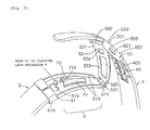
- Figs. 3 and 4 are perspective views, as seen diagonally from above and as seen diagonally from below, respectively, of the clasp device employed in the wrist-fit type communication device.
- the clasp device 5 employed in this embodiment consists of: a metal clasp lower plate 51, of which a base end portion 510 is fixed to the first wrist band 3; a metal clasp intermediate plate 52, of which a base end portion 520 is connected to a tip portion 511 of the clasp lower plate 51 through a first connecting shaft 501; a metal clasp upper box 55, connected to a tip portion 521 of the clasp intermediate plate 52 through a second connecting shaft 502 and fixed to the second wrist band 4; and a clasping lock mechanism 6, which fixes the clasp lower plate 51 and the clasp upper box 55 when the intermediate clasp 52 is rotated around the axis of the first connecting shaft 501 and overlapped onto the clasp lower plate 51, and which can release the fixture.
- the clasp lower plate 51 has a rectangular frame portion formed on the base end portion 510 thereof into which the tip portion of the first wrist band 3 is fitted. It is fixed by two screws 306 secured from the bottom surface thereof so as to be electrically connected to the first antenna plate 30 included in the first wrist band 3 (see Fig. 4).
- the clasp lower plate 51 is bent upward at both sides 513 from the base end portion 510 to the tip portion 511, and has a high strength.
- a rectangular slot 514 is opened at the base end side of the clasp lower plate 51.
- a hook 61 of the clasping lock mechanism 6 is raised upward at its edge of the tip side (Fig. 3).
- a protective cover 71 in the shape of a rectangular prism is fixed by means of welding, etc. at a portion slightly nearer the tip portion than the slot 514. From a rectangular slot 710 formed in the top surface thereof, a projecting contact portion 70 is projected.
- the clasp lower plate 51 and the clasp intermediate plate 52 are connected by: two small tubular portions, formed by bending both sides of the tip portion 511 of the clasp lower plate 51 into the shape of a ring; a tubular portion, formed by bending the center portion of the base end portion of the clasp intermediate plate 52 into the shape of a ring and located between the two tubular portions of the clasp lower plate 51; and the first connecting shaft 501 inserted through these tubular portions.
- the clasp intermediate plate 52 can be rotated around the axis of the first connecting shaft 501.
- the first connecting shaft 501 is crushed at its both end portions, it does not come out from the shaft hole formed by the tubular portions.
- the clasp intermediate plate 52 has two rectangular slots 523 and 524 formed in the longitudinal direction of the metal plate. Of these two slots 523 and 524, a larger slot 523 located at the base end side of the clasp intermediate plate 52 is used for piercing therethrough the protective cover 71 when the clasp intermediate plate 52 is rotated around the first connecting shaft 501 and folded back so as to overlap onto the clasp lower plate 51.
- the smaller slot 524 located near the tip side is used for piercing therethrough the hook 61 when the clasp intermediate plate 52 is folded back so as to overlap onto the clasp lower plate 51 as described above.
- the clasp upper box 55 is fixed at a predetermined longitudinal position.
- a main body cover 550 of the clasp upper box 55 includes a top surface 551 having a slightly curved shape in the longitudinal direction of the second wrist band 4. Side surfaces 552 are formed by folding downward the top surface at the side edges thereof, the cover 550 covers the second wrist band 4.
- the clasp upper box 55 includes a lock unit 80 (Fig. 4) fixed on the side surfaces 552 so that the second wrist band 40 is sandwiched between the clasp upper box 55 and the main body cover 550.
- Fig. 5 is a perspective view of the lock unit employed in the wrist-fit-type communication device.
- the lock unit 80 has two support plates 801 projecting from the end portion located on the tip side in the longitudinal direction of the second wrist band 4. Small holes are formed in these two support plates 801. Since the tubular portion formed by bending the tip portion 521 of the clasp intermediate plate 52 is located at the position where it is in communication with the holes of the support plates 801, the clasp intermediate plate 52 and the lock unit 80 are connected through the second connecting shaft 502 by passing the second connecting shaft 502 through the tubular portion and the holes. That is, the clasp intermediate plate 52 and the clasp upper box 55 are connected through the second connecting shaft 502 and the lock unit 80. For this reason, the clasp upper box 55 can be rotated around the axis of the second connecting shaft 502. Therefore, as shown in Fig. 2, all of the clasp lower plate 51, the clasp intermediate plate 52, and the clasp upper box 55 can be folded back at the respective connecting portions. If folded back in this way, the lower box 51, the clasp intermediate plate 52, and the clasp upper box 55 are overlapped in this order.
- Fig. 6 is a plan view showing configurations of engagement plates and engaging coil springs contained in the lock unit.
- Fig. 7 is a sectional view showing a structure when the lock unit is mounted to the clasp upper box.
- the clasping lock mechanism 6 fixes the clasp lower plate 51 and the clasp upper box 55 when the clasp intermediate plate 52 is overlapped onto the clasp lower plate 51.
- the mechanism comprises engagement plate 81 and 82 (engagement pieces) in the lock unit 80 supported by the clasp upper box 55 on the inner peripheral surface of the second wrist band 4; as shown in Figs. 4 and 5 with respect to the hook 61 shown in Fig. 3.
- the clasping lock mechanism 6 is, as shown in Figs. 6 and 7, used for locking the clasp lower plate 51 and the clasp upper box 55 in engagement with the tip portion of the hook 61. That is, the parts are located when the clasp intermediate plate 52 is overlapped onto the clasp lower plate 51 and the hook passes through the slot of the clasp intermediate plate 52.
- the mechanism 6 includes: a flat rectangular tube-shaped frame 83 of which both sides are opened; two engagement plates 81 and 82 which are arranged inside the frame 83, so that outer end portions 811 and 821 thereof are projected from both sides of the frame 83; and two coil springs 84 and 85, arranged inside the frame 83 between the engagement plates 81 and 82.
- rectangular slots 831 and 832 are formed at the positions where they overlap each other.
- the tip portion of the hook 61 penetrates slots 831 and 832 when the clasp intermediate plate 52 is overlapped onto the clasp lower plate 51.
- the two engagement plates 81 and 82 are arranged with both sides thereof inverted from each other. They are arranged so that a slot 800, from which the hook 61 penetrates when the clasp intermediate plate 52 is overlapped onto the clasp lower plate 51, is formed at the position where it overlaps the slots 831 and 832 of the frame 83.
- the two engagement plates 81 and 82 include: outer end portions 811 and 821, each projected from the opposite side of both side surfaces 552 of the clasp upper box 55; connecting portions 812 and 822, extending straight from the outer end portions 811 and 821 so as to opposingly pass through a position (slot 800) from which the hook 61 appears; and inner end portions 813 and 823, bent inwards on the tip side of the connecting portions 812 and 822 to pass around to the opposite side of the position (slot 800) from which the hook 61 appears.
- the two engagement plates 81 and 82 are arranged in a longitudinally (the direction shown by the arrow A) slidable condition in the frame 83.
- the engaging coil springs 84 and 85 urge the two engagement plates 81 and 82 towards the respective outer end portions.
- the two engagement plates are urged by the engaging coil springs 84 and 85 in the direction in which the inner end portions 813 and 823 approach each other.
- stoppers 836 and 837 raised on the side of the bottom surface of the frame 83 are in abutment with the inner peripheries of the rectangular slots 814 and 824 formed in the engagement plates 81 and 82.
- the inner end portions 813 and 823 are prevented from approaching further.
- the slot 800 from which the hook 61 always penetrates is formed with a fixed width between the inner end portions 813 and 823 of the two engagement plates 81 and 82.
- the outer end portions 811 and 812 are always projecting from both sides of the frame 83 by a fixed length, and the outer end portions 811 and 812 can be put inside the frame 83 if they are pushed from both sides.
- the lock unit 80 is fixed to the clasp upper box 55.
- the second wrist band 4 is clamped between the main body cover 550 of the clasp upper box 55 and the top surface of the lock unit 80, and the clasp upper box 55 is fixed to a predetermined position of the first wrist band 3.
- the lock unit 80 is caught by both side surfaces 552 of the clasp upper box 55 through the engagement plates 81 and 82; the lock unit 80 is removed when it is shifted while pressing in the outer end portions 811 and 812 projected from both side surfaces 552. Therefore, the lock unit 80 can be re-fixed to the clasp upper box 55 after shifting the position of the clasp upper box 55 in the longitudinal direction of the second wrist band 4, so that a correct length of the band is obtained.
- a the clasp upper box-fixing lock mechanism 8 which can adjust a condition where the second wrist band 4 is clamped from the top and bottom between the lock unit 80 and the main body cover 550 of the clasp upper box 55.
- the fixed position of the clasp upper box 55 can thus be changed in the longitudinal direction of the second wrist band 4 by releasing the clamped condition. Therefore, it can be said that of the components constituting the clasp upper box-fixing lock mechanism 8 and the clasping lock mechanism 6, the components provided on the side of the clasp upper box 55 are constructed as one lock unit 80.
- a plurality of dents 49 are formed on the inner peripheral surface in the longitudinal direction of the second wrist band 4 at fixed intervals and on the side of the clasp upper box-fixing lock mechanism 8.
- Engagement projections 86 and 87 to be engaged with several of the dents 49 to prevent the shift of the clasp upper box 55, are formed in two lines on both the left and right of the top surface of the frame 83 which constitutes the lock unit 80. Therefore, the lock unit 80 is mounted to the main body cover 550 of the clasp upper box 55 while adjusting the relative positions between the lock unit 80 and the second wrist band 4 so that the two lines of engagement projections 86 and 87 are engaged with the dents 49.
- index marks 59 are provided for performing alignment of the engagement projections 86 and 87 and the dents 49 with which the engagement projections 86 and 87 should be engaged. Alignment is on the basis of the other dents 49 when bringing predetermined dents 49 into engagement with the engagement projections 86 and 87.
- the index marks 59 are formed at two places on both sides of the slots 555 in the inner peripheral surfaces of the side surfaces 552 of the main body cover 550, as shown in Fig. 8.
- the dents 49 for engaging with the engagement projections 86 and 87 are concealed by the lock unit 80 and are invisible, so that the adjustment may require much labour. In the present embodiment, however, it is convenient if the alignment is performed between the other dents 49 and the positioning index marks 59. This utilizes the fact that the dents 49 are formed at fixed intervals. It thus enables indirect alignment of the engaging projections 86 and 87 and the appropriate dents 49.
- the thus constructed clasp device 5 includes a contact mechanism 7 for electrically connecting the first antenna plate 30 and the second antenna plate 40 when the first wrist band 3 and the second wrist band 4 are clasped to form a loop-like antenna.
- the mechanism has a construction in which the second antenna plate 40 is bare on the inner peripheral surface in the longitudinal direction of the second wrist band 4.
- a projecting contact portion 70 projects from the top surface of the protective cover 71 and comes into contact with a bare portion 400, as shown by one-dot chain line.
- the projecting contact portion 70 is constructed as a part of a metal plate spring which constitutes a contact urging spring 72. The part of the plate spring is accommodated in the protective cover 71.
- the bare portion 400 of the second antenna plate 40 is arranged so that it does not project beyond the tip side of the clasp lower plate 51 when the clasp intermediate plate 52 is overlapped onto the clasp lower plate 51 and clasped.
- the clasp intermediate plate 52 is provided between the first wrist band 3 and the second wrist band 4, it becomes difficult to electrically connect the first antenna plate 30 and the second antenna plate 40 with certainty.
- a slot 523 is formed in the clasp intermediate plate 52 at the position corresponding to the projecting contact portion 70 and the protective cover 71 when the clasp intermediate plate 52 is overlapped onto the clasp lower plate 51.
- the projecting contact portion 70 and the protective cover 71 pass through the slot 523, whereby the projecting contact portion 70 and the bare portion 400 are resiliently and electrically brought into contact with each other. Therefore, the first antenna plate 30 and the second antenna plate 40 can be electrically connected with certainty without changing the basic structure of the three fold clasp device 5.
- the clasp lower plate 51 can be reduced in size.
- the projecting contact portion 70 is urged by the contact urging spring 72 and elastically comes into abutment with the bare portion 400 of the second antenna plate 40.
- the projecting contact portion 70 can thus be electrically connected to the second antenna plate 40 with certainty even if the clasp device 5 has a looseness and a portion of low dimensional accuracy.
- the projecting contact portion 70 is constructed as a part of a metal plate spring used as the contact urging spring 72, so that the number of components can be reduced. If the plate spring is used as the contact urging spring 72, a large urging force can be obtained with a thin plate so that it is suitably incorporated into the clasp device 5.
- the contact urging spring 72 is covered with the protective cover 71 and is not bare, user's hands and other objects do not touch the contact urging spring 72 to deform it.
- the projecting contact portion 70 is urged by the contact urging spring 72 so as to be electrically connected to the second antenna plate 40 with certainty.
- the contact urging spring 72 does not injure to the user's wrist and so forth.
- the first wrist band 3 and the second wrist band 4 are connected through the three fold clasp device 5. Therefore, when the wrist-fit-type communication device 1 is fitted to the user's wrist, the clasp intermediate plate 52 is overlapped onto the clasp lower plate 51 after passing the wrist through a ring formed by the device main body 2, the first wrist band 3, the clasp device 5, and the second wrist band 4. Thereafter, if the clasp upper box 55 is pressed toward the clasp lower plate 51, the hook 61 raised on the top surface of the clasp lower plate 51 passes through the slot 524 of the clasp intermediate plate 52.
- the projecting contact portion 70 projecting from the protective cover on the top surface of the clasp lower plate 51 is elastically in abutment with the second antenna plate 40 which is bare on the inner peripheral surface of the second wrist band 4.
- the first antenna plate 30 and the second antenna plate 40 are electrically connected through the clasp lower plate 51, the contact urging spring 72 in the protective cover 71, and the projecting contact portion 70; to form a loop-like antenna.
- the engagement plates 81 and 82 are disengaged from the hook 61 by simply pushing in the outer end portions 811 and 821 of the engagement plates 81 and 82 projecting from both side surfaces 552 of the clasp upper box 55, so that the clasp can be easily released.
- the thin engagement plates 81 and 82 are used as the described lock mechanism.
- the two engagement plates 81 and 82 are arranged so as to pass around to the opposite side of the hook 61 in the reverse direction to each other. They are arranged two-dimensionally without overlapping. Therefore, since the lock unit 80 can be made thin, it is suitably arranged in the clasp upper box 55. Moreover, the lock unit 80 is made detachable with respect to the clasp upper box 55 using the engagement plates 81 and 82.
- the clasp upper box 55 is removed from the second wrist band 4 so as to change the fixed position thereof, so that the length of the band can be adjusted while using a small number of components.
- the wrist-fit-type communication device 1 of this embodiment since the three fold clasp device 5 is used for clasping the first wrist band 3 and the second wrist band 4; clasping is performed after passing the wrist through a ring formed by the device main body 2, the first wrist band 3, the clasp device 5, and the second wrist band 4. Therefore, there is no inconvenience such that the wrist-fit-type communication device 1 falls off of the wrist. Since the first antenna plate 30 and the second antenna plate 40 are covered with a thickish synthetic resin (insulating materials 301 and 401) and are thus relatively hard the wrist bands can be easily fitted to the wrist. Therefore, good use can be made of the advantage of adopting synthetic resin as insulating materials for the first wrist band 3 and the second wrist band 4. Thus, the first wrist band 3 and the second wrist band 4 are manufactured at low cost by integrally forming the first antenna plate 30 and the second antenna plate 40 with synthetic resin.
- the bare portion of the second antenna plate 40 is formed to the extent that it does not project beyond the tip side of the clasp lower plate 51 when the clasp intermediate plate 52 is overlapped onto the clasp lower plate 51. For this reason, of the bare portion 400 of the second antenna plate 40, the bare portion located on the tip side of the second wrist band 4 is completely concealed by the first wrist band 3. The bare portion located on the base end side of the second wrist band 4 is concealed by the clasp lower plate 51. Therefore, since the skin does not touch the bare portion of the second antenna plate 40, a good feeling of fitting can be provided. In addition, since the bare portion 400 of the second antenna plate is not stained, poor electrical connection is avoided when the length of the band is adjusted even if electrical connection is effected at a portion which has not previously been used for the electrical connection.
- Fig. 10 is a perspective view, as seen diagonally from above, of a clasp device employed in a wrist-fit-type communication device according to a modification of the first embodiment.
- the protective cover 71 in the shape of a rectangular prism is fixed to the clasp lower plate 51.
- the projecting contact portion 70 is projected from the top surface thereof.
- a metal contact urging spring 76 may be fixed by a method such as welding to the base end portion 510 of the clasp lower plate 51.
- the upper end thereof may be utilized as a projecting contact portion 75.
- the projecting contact portion 75 elastically comes into contact with the bare portion 400 of the second antenna plate 40 by avoiding the clasp intermediate plate 52. Thus, they are electrically connected when the first wrist band 3 and the second wrist band 4 are clasped together.
- Fig. 11 is an illustration showing an overall configuration of a wrist-fit-type communication device according to another embodiment of the present invention.
- Fig. 12 is a sectional view showing a main part thereof.
- a wrist-fit-type communication device 1 according to this embodiment has the same basic construction as that of the first embodiment, the corresponding portions are indicated by the same reference numerals, and a detailed description thereof will be omitted. As shown in Figs. 11 and 12, the wrist-fit-type communication device 1 according to this embodiment is similar to the first embodiment in that it has a clasp device 5A.
- the device has: a device main body 2 containing communication circuits; a first wrist band 3 covering a metal first antenna plate 30, extending from the 6 o'clock side of a wristwatch of the device main body 2, with a flexible insulating material 301 formed of synthetic resin; a second wrist band 4 covering a metal second antenna plate 40, extending from the 12 o'clock side, with a flexible insulating material 401 formed of synthetic resin; and a clasp device 5A including a contact mechanism 7A for electrically connecting the first antenna plate 30 and the second antenna plate 40 to form a loop-like antenna when the second wrist band 4 and the first wrist band 3 are clasped together.
- the clasp device 5A is similar to the first embodiment in that it has the three fold structure including: a clasp lower plate 51, of which the base end portion is adhered to the first wrist band 3; a clasp intermediate plate 52, connected to the tip portion of the clasp lower plate 51 through a first connecting shaft 501; a clasp upper box 55A, connected to the tip portion of the clasp intermediate plate 52 through a second connecting shaft 502, and fixed to the second wrist band 4; and a clasping lock mechanism 6A which fixes the clasp upper box 55A to the clasp lower plate 51 when the clasp intermediate plate 52 is rotated around the axis of the first connecting shaft 501 and overlapped onto the clasp lower plate 51, and which can release the fixed condition.
- the wrist-fit-type communication device 1 of this embodiment differs from the first embodiment in that an engagement plate 90 formed separately from a main body portion 550A of the clasp upper box 55A is used in the clasping lock mechanism 6A, as shown in detail in Figs. 13 and 14.
- Fig. 13 is a sectional view showing a configuration of the clasp upper box of the wrist-fit-type communication device.
- Fig. 14 is a sectional view showing a state where the clasping of the wrist bands is performed using the clasp device including the clasp upper box.
- a hook 91A projects from the top surface of the clasp lower plate 51 in a shape bent towards a tip portion 511 of the clasp lower plate 51.
- the engagement plate 90 is formed on the side of the second wrist band separately from the main body portion 550A of the clasp upper box 55.
- the engagement plate 90 is rotatable around the axis of the second connecting shaft 502, and fixes the clasp upper box 55A to the clasp lower box 51 by utilizing the described action.
- a lower end portion 91 of the engagement plate 90 includes an engagement shaft 92 which enters the hook 61A, as shown by the arrow D in Fig. 14.
- Shaft 92 is to be engaged with the hook 61A when the engagement plate 90 rotates around the axis of the second connecting shaft 502 with the clasp intermediate plate 52 overlapped onto the clasp lower plate 51. Therefore, when the engagement plate 90A is to be pressed in the direction of the arrow D so as to move towards the second wrist band 4 even after the engagement shaft 92 has been engaged with the hook 61A, the force acts as a force for pressing the engagement plate 90 toward the clasp lower plate 51, as shown by the arrow C.
- the engaged portion of the hook 61A and the engagement shaft 92 are used as a fulcrum.
- engagement holes 519 are formed in both side surfaces 518 of the clasp lower plate 51, respectively.
- Engaging small projections 94 are formed inside both side surfaces 93 of the engagement plate 90 at positions corresponding to the engagement holes 519. For this reason, as shown in Fig. 12, when both side surfaces 93 of the engagement plate 90 and both side surfaces 518 of the clasp lower plate 51 overlap; the engaging small projections 94 are fitted into the engagement holes 519. As a result, the main body portion 550A of the clasp upper box 55 is fixed to the clasp lower plate 51 through the engagement plate 90. Thus, the first wrist band 3 and the second wrist band 4 are clasped together.
- the contact mechanism 7A for electrically connecting the first antenna plate 30 and the second antenna plate 40 to form a loop-like antenna the second antenna plate 40 is bare on the inner peripheral surface of the second wrist band 4 in the longitudinal direction.
- the projecting contact portion 70A is projected on the upper surface of the clasp lower plate 51 which is electrically connected to the first antenna plate 30, similarly to the first embodiment.
- the projecting contact portion 70A is formed by processing a part of the plate spring as the contact urging spring 72A. It is raised in such a form that it covers the hook 61A from the back thereof on the side of the base end portion 510 of the clasp lower plate 51 rather than the hook 61A. The position where the projecting contact portion 70A is thus arranged does not overlap the clasp intermediate plate 52 even when the clasp intermediate plate 52 is overlapped onto the clasp lower plate 51. Thus, the projecting contact portion 70A elastically comes into abutment with the bare portion 400 of the second antenna plate 40 by avoiding the clasp intermediate plate 52 when the first wrist band 3 and the second wrist band 4 are clasped.
- the first antenna plate 30 and the second antenna plate 40 are electrically connected through the clasp lower plate 51, the contact urging spring 72A, and the projecting contact portion 70A to form a loop-like antenna.
- the bare portion of the second antenna plate 40 is formed to the extent that it does not project beyond the tip side of the clasp lower plate 51 when the clasp intermediate plate 52 is overlapped onto the clasp lower plate 51.
- the user's skin does not touch the bare portion of the second antenna plate 40.
- the engagement plate 90 When the wrist-fit-type communication device 1 is removed from the wrist, the engagement plate 90 is rotated around the axis of the second connecting shaft 502. As a result, the engagement shaft 92 which has been engaged with the hook 61A comes out of the hook 61A after the small projections 94 formed on both side surfaces 93 of the engagement plate 90 have come out of the engagement holes 519 formed in both side surfaces 518 of the clasp lower plate 51.
- the clasp upper box 55A also includes a clasp upper box-fixing lock mechanism 8A. This adjusts the second wrist band 4 being clamped from the top and bottom on the side of its main body portion 550A, and the fixed position of the clasp upper box 55A in the longitudinal direction of the second wrist band 4 by releasing this clamped condition.
- a supporting shaft 553A is arranged between the both side surfaces 552A of the main body portion 550A of the clasp upper box 55.
- a rotary lever 80A including a fixed pawl 86A (engagement projection) is supported by the supporting shaft 553A, and a plurality of dents 49 are formed on the inner peripheral surface in the longitudinal direction of the second wrist band 4 at fixed intervals.
- the clasp upper box 55A can be shifted to a predetermined position in the lengthwise direction of the second wrist band 4 with the lever 80A rotated around the axis of the supporting shaft 553A to disengage the fixed pawl 86A from the dents 49.
- the lever 80A is rotated around the axis of the supporting shaft 553A to bring the fixed pawl 86A into engagement with the dents 49.
- the second wrist band 4 is clamped between the fixed pawl 86A and the main body portion 550A of the clasp upper box 55A.
- the clasp upper box 55A is fixed to the second wrist band 4.
- the first wrist band 3 is extended from the 6 o'clock side of the device main body 2, and the second wrist band 4 is extended from the 12 o'clock side.
- the first wrist band 3 may be extended from the 12 o'clock side of the device main body 2, and the second wrist band 4 may be extended from the 6 o'clock side.
- the constructions according to the above embodiments may be combined.
- the first wrist band and the second wrist band are clasped after passing a user's wrist through a ring formed by the device main body, the first wrist band, the clasp device, and the second wrist band. Therefore, there is no inconvenience such that the wrist-fit-type communication device erroneously falls off of the wrist.
- the wrist bands can be easily fitted to the wrist even when the first wrist band and the second wrist band are relatively hard. If synthetic resin is employed as an insulating material for covering the antenna plates in each of the wrist bands, the wrist bands are further likely to become inflexible.
- the fitting property to the wrist is high.
- maximum use can be made of the advantage of using synthetic resin as insulating materials.
- the wrist bands can be manufactured integrally with the antenna plates.
- the three fold clasp device can prevent the bare portion of the second antenna plate from touching the user's skin. Therefore, since the bare portion of the second antenna plate is not stained, poor electrical connection does not result when the length of the band is adjusted, even if electrical connection is effected at a portion which has not previously been used for the electrical connection.
- the projecting contact portion is urged by the contact urging spring so as to come into abutment with the bare portion of the second antenna plate.
- the projecting contact portion and the second antenna plate are electrically connected with certainty even if a looseness and a reduction in dimensional accuracy are present in any part of the clasp device.
Landscapes
- Physics & Mathematics (AREA)
- General Physics & Mathematics (AREA)
- Details Of Aerials (AREA)
- Support Of Aerials (AREA)
- Telephone Set Structure (AREA)
- Mobile Radio Communication Systems (AREA)
- Structure Of Receivers (AREA)
Abstract
Description
Claims (17)
- A wrist-fit-type communication device comprising a device main body containing communication circuits; a first wrist band including a first antenna plate; a second wrist band including a second antenna plate; and a clasp device including a contact mechanism for electrically connecting said first antenna plate and said second antenna plate to form a loop-like antenna when said second wrist band and said first wrist band are clasped together by the clasp,
wherein said clasp device has a three fold structure including a clasp lower plate fixed to said first wrist band; a clasp intermediate plate connected to said clasp lower plate; a clasp upper box connected to said clasp intermediate plate and fixed to said second wrist band; and a clasping lock mechanism which releasably fixes said clasp upper box to said clasp lower plate. - A wrist-fit-type communication device according to claim 1, wherein said first and second wrist bands include insulating material in the form of synthetic resin.
- A wrist-fit-type communication device according to claim 1 or 2, having a contact mechanism which includes: a portion of said second antenna plate formed on the inner peripheral surface of said second wrist band, and a projecting contact portion which projects from said clasp lower plate, which is electrically connected to said first antenna plate, and which comes into abutment with said portion of said second antenna plate to be electrically connected thereto when said first wrist band and said second wrist band are clasped together by said clasp.
- A wrist-fit-type communication device according to claim 3, wherein a slot is formed in the clasp intermediate plate such that said projecting contact portion passes through said slot to come into abutment with the said portion of said second antenna plate when said first wrist band and said second wrist band are clasped together by said clasp.
- A wrist-fit-type communication device according to claim 3, wherein said projecting contact portion is constructed so as to come into abutment with the said portion of said second antenna plate by avoiding said clasp intermediate plate when said first wrist band and said second wrist band are clasped together by said clasp.
- A wrist-fit-type communication device according to any one of claims 3 to 5, wherein said projecting contact portion is urged into contact with the said portion of said second antenna plate by a contact urging spring.
- A wrist-fit-type communication device according to claim 6, wherein said projecting contact portion is constructed as a part of said contact urging spring.
- A wrist-fit-type communication device according to claim 6 or 7, wherein a protective cover for covering said contact urging spring is formed on the upper surface of said clasp lower plate, and said projecting contact portion projects from the upper surface of said protective cover.
- A wrist-fit-type communication device according to any one of claims 3 to 8, wherein the portion of said second antenna plate is formed so that it does not project beyond said clasp lower plate when said clasp intermediate plate is overlapped onto said clasp lower plate.
- A wrist-fit-type communication device according to any one of claims 1 to 9, wherein said clasp upper box includes a clasp upper box-fixing lock mechanism which can adjust a clamped condition of said second wrist band and the fixed position of said clasp upper box in the longitudinal direction of said second wrist band by releasing the clamped condition.
- A wrist-fit-type communication device according to claim 10, wherein a plurality of dents are formed on the inner peripheral surface in the longitudinal direction of said second wrist band at predetermined intervals, and said clasp upper box-fixing lock mechanism includes engagement projections which are engaged with any of said dents to prevent a shift of said clasp upper box on said second wrist band.
- A wrist-fit-type communication device according to claim 11, wherein said dents are formed in the longitudinal direction of said second wrist band at fixed intervals, and said clasp upper box includes index marks for performing alignment of said engagement projections and the dents.
- A wrist-fit-type communication device according to any one of claims 1 to 12, wherein of components constituting a or said clasp upper box-fitting lock mechanism and said clasping lock mechanism, components formed on the side of said clasp upper box are constructed in one piece as a lock unit.
- A wrist-fit-type communication device according to any one of claims 1 to 13, wherein said clasping lock mechanism has a hook on said clasp lower plate, and an engagement piece on said clasp upper box and which is engaged with said hook when said clasp upper box is pressed towards said clasp lower plate, and
wherein said engagement piece is disengaged from said hook when an external operation for releasing the engagement with said hook is performed. - A wrist-fit-type communication device according to claim 14, wherein said engagement piece has two engagement plates including outer end portions each of which project from the opposite side of both side surfaces of said clasp upper box, and inner end portions each passing around from said outer end portions to the opposite side of said hook to be engaged with said hook at the opposite side, and
wherein said two engagement plates are urged by engaging springs towards the respective outer end portions, whereby said inner end portions are elastically engaged with said hook, are displaced against the engaging springs when said outer end portions are pressed by both side surfaces of said clasp upper box, and are disengaged from said hook. - A wrist-fit-type communication device according to claim 15, wherein said inner end portions are constructed so as to pass around to the opposite side of said hook in the reverse direction to each other, whereby said two engagement plates are arranged two-dimensionally without overlapping.
- A wrist-fit-type communication device according to any one of claims 1 to 12, wherein said clasping lock mechanism has a hook on said clasp lower plate, and an engagement plate which is formed on the side of said second wrist band separately from a main body portion of said clasp upper box, and rotatably supported around the axis of a connecting shaft, and
wherein said engagement plate includes an engagement shaft which enters said hook to be engaged with said hook while said engagement plate is rotated around the axis of said connecting shaft with said clasp intermediate plate overlapped onto said clasp lower plate, and engaging small projections which are fitted into engagement holes formed in both side surfaces of said clasp lower plate when said engagement plate is pressed toward said clasp lower plate using the engaged portion of said engagement shaft and said hook as a fulcrum after said engagement shaft has been engaged with said hook.
Applications Claiming Priority (3)
| Application Number | Priority Date | Filing Date | Title |
|---|---|---|---|
| JP7220597 | 1997-03-25 | ||
| JP72205/97 | 1997-03-25 | ||
| JP9072205A JPH10271196A (en) | 1997-03-25 | 1997-03-25 | Arm-mounted communication device |
Publications (3)
| Publication Number | Publication Date |
|---|---|
| EP0867968A2 true EP0867968A2 (en) | 1998-09-30 |
| EP0867968A3 EP0867968A3 (en) | 1999-01-13 |
| EP0867968B1 EP0867968B1 (en) | 2003-11-05 |
Family
ID=13482514
Family Applications (1)
| Application Number | Title | Priority Date | Filing Date |
|---|---|---|---|
| EP98302234A Expired - Lifetime EP0867968B1 (en) | 1997-03-25 | 1998-03-24 | Wrist-fit-type communication device |
Country Status (5)
| Country | Link |
|---|---|
| US (1) | US6175729B1 (en) |
| EP (1) | EP0867968B1 (en) |
| JP (1) | JPH10271196A (en) |
| DE (1) | DE69819388T2 (en) |
| TW (1) | TW428387B (en) |
Cited By (5)
| Publication number | Priority date | Publication date | Assignee | Title |
|---|---|---|---|---|
| EP1416582A1 (en) * | 2002-10-28 | 2004-05-06 | ETA SA Manufacture Horlogère Suisse | Portable electronic device with an electric connection inside the device case |
| EP1498044A1 (en) * | 2003-07-18 | 2005-01-19 | Tissot S.A. | Clasp for an antenna-including bracelet and bracelet including such a clasp |
| WO2009121928A1 (en) * | 2008-04-02 | 2009-10-08 | The Swatch Group Management Services Ag | Wrist watch |
| CH710089A1 (en) * | 2014-09-12 | 2016-03-31 | José Carlos Fernandes Demétrio | Bracelet with wireless connectivity. |
| CN106558758A (en) * | 2016-11-28 | 2017-04-05 | 深圳众思科技有限公司 | Wearable device |
Families Citing this family (29)
| Publication number | Priority date | Publication date | Assignee | Title |
|---|---|---|---|---|
| WO2001017298A1 (en) * | 1999-09-02 | 2001-03-08 | Automated Business Companies | Communication and proximity authorization systems |
| US7181701B2 (en) * | 2003-01-03 | 2007-02-20 | Microsoft Corporation | Glanceable information system and method |
| US7792121B2 (en) * | 2003-01-03 | 2010-09-07 | Microsoft Corporation | Frame protocol and scheduling system |
| US7130664B1 (en) | 2003-06-12 | 2006-10-31 | Williams Daniel P | User-based signal indicator for telecommunications device and method of remotely notifying a user of an incoming communications signal incorporating the same |
| CA2439722A1 (en) * | 2003-09-04 | 2005-03-04 | Vernon George Houle | A method of controlling movement on the inside and around the outside of a facility |
| US6954659B2 (en) * | 2003-11-24 | 2005-10-11 | World Mobile Technologies, Inc. | Fashion accessory with wireless signal alerting device |
| US8073548B2 (en) * | 2004-08-24 | 2011-12-06 | Sensors For Medicine And Science, Inc. | Wristband or other type of band having an adjustable antenna for use with a sensor reader |
| US7593755B2 (en) * | 2004-09-15 | 2009-09-22 | Microsoft Corporation | Display of wireless data |
| US7513019B2 (en) * | 2005-01-05 | 2009-04-07 | Microsoft Corporation | Fastening mechanisms maintaining electrical connections among fastened components |
| JP4593336B2 (en) * | 2005-03-28 | 2010-12-08 | シチズンホールディングス株式会社 | Band connection structure with built-in conductive wiring |
| AT10310U1 (en) * | 2007-10-01 | 2009-01-15 | Hirsch Armbaender | CLOSURE FOR A BRACELET |
| US8608036B2 (en) * | 2007-11-16 | 2013-12-17 | Belkin International, Inc. | Clamp braces and methods for manufacturing, selling, and using the same |
| US8400270B2 (en) * | 2008-03-14 | 2013-03-19 | General Electric Company | Systems and methods for determining an operating state using RFID |
| US20110199303A1 (en) * | 2010-02-18 | 2011-08-18 | Simpson Samuel K | Dual wrist user input system |
| US8350695B2 (en) | 2010-06-24 | 2013-01-08 | Lojack Operating Company, Lp | Body coupled antenna system and personal locator unit utilizing same |
| EP2502515B1 (en) * | 2011-03-21 | 2013-09-04 | The Swatch Group Management Services AG | Bracelet clasp |
| JP5895993B2 (en) * | 2013-12-25 | 2016-03-30 | セイコーエプソン株式会社 | Biological information measuring device |
| KR102173726B1 (en) * | 2014-01-03 | 2020-11-03 | 삼성전자주식회사 | Terminal for wearing on the wrist |
| US20150254967A1 (en) * | 2014-03-04 | 2015-09-10 | Dequincy A. Hyatt | Tracking and monitoring system |
| US9152129B2 (en) * | 2014-06-25 | 2015-10-06 | Dilshan Thilina Modaragamage | Electronic watch clasp systems and methods |
| US9277791B2 (en) | 2014-07-21 | 2016-03-08 | Microsoft Technology Licensing, Llc | Adjustable band mechanism |
| US9525201B2 (en) | 2014-10-27 | 2016-12-20 | Nokia Technologies Oy | Hinge that serves as a radiator |
| US9609922B2 (en) * | 2015-04-28 | 2017-04-04 | Motorola Mobility Llc | Watch and band with latch attachment |
| US9461386B1 (en) * | 2015-10-09 | 2016-10-04 | Pebble Technology, Corp. | Spring pin electrical connector |
| CN106909072A (en) | 2015-12-29 | 2017-06-30 | 小米科技有限责任公司 | Intelligent watch |
| JP6172341B2 (en) * | 2016-01-04 | 2017-08-02 | オムロンヘルスケア株式会社 | Biological information measuring device |
| CN111158232B (en) * | 2019-06-13 | 2023-12-22 | 广东小天才科技有限公司 | Intelligent host, multi-antenna line switching method and intelligent watch |
| CN110558689B (en) * | 2019-07-23 | 2021-03-30 | 华为技术有限公司 | A connection structure and wearable product |
| CN115047747B (en) * | 2022-08-16 | 2022-11-01 | 歌尔股份有限公司 | Intelligent watch |
Family Cites Families (12)
| Publication number | Priority date | Publication date | Assignee | Title |
|---|---|---|---|---|
| IT8321828U1 (en) * | 1983-05-13 | 1984-11-13 | Lascor Spa | EXTENDABLE CLOSING CLASP SPECIFICALLY FOR FLEXIBLE LEATHER OR PLASTIC WATCH STRAP |
| FR2548879B1 (en) * | 1983-07-11 | 1985-11-22 | Omega Sa | REMOVABLE HINGE FOR BRACELET |
| US4922260A (en) * | 1989-01-18 | 1990-05-01 | At & E Corporation | Adjustable watchband with embedded antenna |
| US4977614A (en) * | 1989-10-23 | 1990-12-11 | Motorola, Inc. | Wristband with loop antenna |
| US5135694A (en) | 1989-11-10 | 1992-08-04 | Seiko Epson Corporation | Electronic device wristband |
| JP2890743B2 (en) | 1990-01-10 | 1999-05-17 | セイコーエプソン株式会社 | Clamping device for antenna band for portable information equipment |
| US5179733A (en) * | 1990-04-23 | 1993-01-12 | Seiko Epson Corporation | Wristwatch band with radio antenna |
| US5134724A (en) * | 1990-05-08 | 1992-07-28 | Seiko Corp. | Wrist band for wrist-mounted radio with an uninsulated buckle |
| JP2985296B2 (en) | 1990-05-16 | 1999-11-29 | セイコーエプソン株式会社 | Antenna connection device for electronic equipment |
| WO1992002970A1 (en) * | 1990-07-27 | 1992-02-20 | Motorola, Inc. | Insulated clasp for a wrist band loop antenna |
| US5303421A (en) * | 1992-02-27 | 1994-04-12 | Motorola, Inc. | Method and apparatus for coupling straps of a wrist worn device |
| US5742256A (en) * | 1993-05-07 | 1998-04-21 | Seiko Epson Corporation | Wristband having embedded electrically conductive members for a wrist-mountable type electronic device |
-
1997
- 1997-03-25 JP JP9072205A patent/JPH10271196A/en not_active Withdrawn
-
1998
- 1998-03-24 US US09/046,708 patent/US6175729B1/en not_active Expired - Lifetime
- 1998-03-24 EP EP98302234A patent/EP0867968B1/en not_active Expired - Lifetime
- 1998-03-24 DE DE69819388T patent/DE69819388T2/en not_active Expired - Fee Related
- 1998-03-25 TW TW087104466A patent/TW428387B/en not_active IP Right Cessation
Cited By (11)
| Publication number | Priority date | Publication date | Assignee | Title |
|---|---|---|---|---|
| EP1416582A1 (en) * | 2002-10-28 | 2004-05-06 | ETA SA Manufacture Horlogère Suisse | Portable electronic device with an electric connection inside the device case |
| US6854978B2 (en) | 2002-10-28 | 2005-02-15 | Eta Sa Manufacture Horlogere Suisse | Portable electronic device including means for establishing an electrical connection inside a case of said device |
| EP1498044A1 (en) * | 2003-07-18 | 2005-01-19 | Tissot S.A. | Clasp for an antenna-including bracelet and bracelet including such a clasp |
| US7126550B2 (en) | 2003-07-18 | 2006-10-24 | Tissot S.A. | Clasp for bracelet incorporating an antenna and bracelet including the same |
| WO2009121928A1 (en) * | 2008-04-02 | 2009-10-08 | The Swatch Group Management Services Ag | Wrist watch |
| US8770830B2 (en) | 2008-04-02 | 2014-07-08 | The Swatch Group Management Services Ag | Watch strap or bracelet |
| CH710089A1 (en) * | 2014-09-12 | 2016-03-31 | José Carlos Fernandes Demétrio | Bracelet with wireless connectivity. |
| WO2016038058A3 (en) * | 2014-09-12 | 2016-05-26 | Fernandes Demetrio José Carlos | Connected bracelet |
| US10455907B2 (en) | 2014-09-12 | 2019-10-29 | Geosatis S.A. | Bracelet for a timepiece |
| CN106558758A (en) * | 2016-11-28 | 2017-04-05 | 深圳众思科技有限公司 | Wearable device |
| CN106558758B (en) * | 2016-11-28 | 2024-06-11 | 南昌黑鲨科技有限公司 | Wearable device |
Also Published As
| Publication number | Publication date |
|---|---|
| JPH10271196A (en) | 1998-10-09 |
| EP0867968B1 (en) | 2003-11-05 |
| TW428387B (en) | 2001-04-01 |
| EP0867968A3 (en) | 1999-01-13 |
| US6175729B1 (en) | 2001-01-16 |
| DE69819388T2 (en) | 2004-08-12 |
| DE69819388D1 (en) | 2003-12-11 |
Similar Documents
| Publication | Publication Date | Title |
|---|---|---|
| EP0867968B1 (en) | Wrist-fit-type communication device | |
| US5601222A (en) | Magnifying wristband | |
| EP1161358B1 (en) | Case for mobile terminal | |
| EP0731395A2 (en) | Watch band attachment mechanism | |
| CN116530760B (en) | Watchband, timepiece, and watchband length adjustment mechanism | |
| CN107019297A (en) | Table is buckled, watchband and clock and watch | |
| JP4232792B2 (en) | Nakadome | |
| US20180343987A1 (en) | Folding clasp | |
| ATE435601T1 (en) | CLASP FOR A BRACELET EQUIPPED WITH AN ANTENNA AND BRACELET COMPRISING THIS CLASP | |
| KR20210051780A (en) | Connecting apparatus for watch strap and watch strap with the same | |
| CN107280157B (en) | Watchband structure and intelligent watch with watchband structure | |
| EP0125930A2 (en) | Strap assembly | |
| CN109077394B (en) | Buckle and timepiece | |
| US20120080464A1 (en) | Wearable Band for Receiving a Clip-On Device, Docking Accessories, and Methods of Use | |
| US20250204654A1 (en) | Band-Holding Mechanism, Wrist-Worn Device, Wrist-Worn Device Main Body, Band-Holding Unit, And Band | |
| CN100556331C (en) | Connection structure of tape with built-in conductive wiring | |
| CN113243632B (en) | Buckle structure for watch, watch strap and watch | |
| CN216123938U (en) | Wearable device | |
| JPH09168413A (en) | Arm-worn portable device and method for adjusting band length thereof | |
| CN114831393A (en) | Buckle, band, and wrist-worn device | |
| CN108354281B (en) | Case for portable device, and timepiece | |
| JP4147801B2 (en) | Detachable mechanism and electronic device | |
| JP3494000B2 (en) | Arm-mounted communication device | |
| JP3621491B2 (en) | Trinket structure of jewelry | |
| CN217524132U (en) | Watch structure |
Legal Events
| Date | Code | Title | Description |
|---|---|---|---|
| PUAI | Public reference made under article 153(3) epc to a published international application that has entered the european phase |
Free format text: ORIGINAL CODE: 0009012 |
|
| AK | Designated contracting states |
Kind code of ref document: A2 Designated state(s): CH DE FR GB LI NL |
|
| AX | Request for extension of the european patent |
Free format text: AL;LT;LV;MK;RO;SI |
|
| PUAL | Search report despatched |
Free format text: ORIGINAL CODE: 0009013 |
|
| AK | Designated contracting states |
Kind code of ref document: A3 Designated state(s): AT BE CH DE DK ES FI FR GB GR IE IT LI LU MC NL PT SE |
|
| AX | Request for extension of the european patent |
Free format text: AL;LT;LV;MK;RO;SI |
|
| 17P | Request for examination filed |
Effective date: 19990618 |
|
| AKX | Designation fees paid |
Free format text: CH DE FR GB LI NL |
|
| 17Q | First examination report despatched |
Effective date: 20020419 |
|
| GRAH | Despatch of communication of intention to grant a patent |
Free format text: ORIGINAL CODE: EPIDOS IGRA |
|
| GRAS | Grant fee paid |
Free format text: ORIGINAL CODE: EPIDOSNIGR3 |
|
| GRAA | (expected) grant |
Free format text: ORIGINAL CODE: 0009210 |
|
| AK | Designated contracting states |
Kind code of ref document: B1 Designated state(s): CH DE FR GB LI NL |
|
| REG | Reference to a national code |
Ref country code: GB Ref legal event code: FG4D |
|
| REG | Reference to a national code |
Ref country code: CH Ref legal event code: EP |
|
| REF | Corresponds to: |
Ref document number: 69819388 Country of ref document: DE Date of ref document: 20031211 Kind code of ref document: P |
|
| REG | Reference to a national code |
Ref country code: CH Ref legal event code: NV Representative=s name: PATENTANWAELTE FELDMANN & PARTNER AG |
|
| ET | Fr: translation filed | ||
| PLBE | No opposition filed within time limit |
Free format text: ORIGINAL CODE: 0009261 |
|
| STAA | Information on the status of an ep patent application or granted ep patent |
Free format text: STATUS: NO OPPOSITION FILED WITHIN TIME LIMIT |
|
| 26N | No opposition filed |
Effective date: 20040806 |
|
| PGFP | Annual fee paid to national office [announced via postgrant information from national office to epo] |
Ref country code: FR Payment date: 20060308 Year of fee payment: 9 |
|
| PGFP | Annual fee paid to national office [announced via postgrant information from national office to epo] |
Ref country code: DE Payment date: 20060316 Year of fee payment: 9 |
|
| REG | Reference to a national code |
Ref country code: FR Ref legal event code: ST Effective date: 20071130 |
|
| PG25 | Lapsed in a contracting state [announced via postgrant information from national office to epo] |
Ref country code: DE Free format text: LAPSE BECAUSE OF NON-PAYMENT OF DUE FEES Effective date: 20071002 |
|
| PG25 | Lapsed in a contracting state [announced via postgrant information from national office to epo] |
Ref country code: FR Free format text: LAPSE BECAUSE OF NON-PAYMENT OF DUE FEES Effective date: 20070402 |
|
| PGFP | Annual fee paid to national office [announced via postgrant information from national office to epo] |
Ref country code: NL Payment date: 20090315 Year of fee payment: 12 |
|
| PGFP | Annual fee paid to national office [announced via postgrant information from national office to epo] |
Ref country code: GB Payment date: 20090318 Year of fee payment: 12 |
|
| REG | Reference to a national code |
Ref country code: NL Ref legal event code: V1 Effective date: 20101001 |
|
| GBPC | Gb: european patent ceased through non-payment of renewal fee |
Effective date: 20100324 |
|
| PG25 | Lapsed in a contracting state [announced via postgrant information from national office to epo] |
Ref country code: NL Free format text: LAPSE BECAUSE OF NON-PAYMENT OF DUE FEES Effective date: 20101001 |
|
| PG25 | Lapsed in a contracting state [announced via postgrant information from national office to epo] |
Ref country code: GB Free format text: LAPSE BECAUSE OF NON-PAYMENT OF DUE FEES Effective date: 20100324 |
|
| PGFP | Annual fee paid to national office [announced via postgrant information from national office to epo] |
Ref country code: CH Payment date: 20110314 Year of fee payment: 14 |
|
| REG | Reference to a national code |
Ref country code: CH Ref legal event code: PL |
|
| PG25 | Lapsed in a contracting state [announced via postgrant information from national office to epo] |
Ref country code: LI Free format text: LAPSE BECAUSE OF NON-PAYMENT OF DUE FEES Effective date: 20120331 Ref country code: CH Free format text: LAPSE BECAUSE OF NON-PAYMENT OF DUE FEES Effective date: 20120331 |