EP0867617A2 - Variable capacity swash plate compressor - Google Patents
Variable capacity swash plate compressor Download PDFInfo
- Publication number
- EP0867617A2 EP0867617A2 EP98302181A EP98302181A EP0867617A2 EP 0867617 A2 EP0867617 A2 EP 0867617A2 EP 98302181 A EP98302181 A EP 98302181A EP 98302181 A EP98302181 A EP 98302181A EP 0867617 A2 EP0867617 A2 EP 0867617A2
- Authority
- EP
- European Patent Office
- Prior art keywords
- swash plate
- drive shaft
- rotatable member
- pistons
- side area
- Prior art date
- Legal status (The legal status is an assumption and is not a legal conclusion. Google has not performed a legal analysis and makes no representation as to the accuracy of the status listed.)
- Granted
Links
- 238000006243 chemical reaction Methods 0.000 claims abstract description 34
- 230000006835 compression Effects 0.000 claims abstract description 31
- 238000007906 compression Methods 0.000 claims abstract description 31
- 239000003507 refrigerant Substances 0.000 description 11
- 230000003247 decreasing effect Effects 0.000 description 6
- 238000005299 abrasion Methods 0.000 description 4
- 230000007423 decrease Effects 0.000 description 4
- 238000010276 construction Methods 0.000 description 2
- 230000015556 catabolic process Effects 0.000 description 1
- 238000006731 degradation reaction Methods 0.000 description 1
- 230000000694 effects Effects 0.000 description 1
- 238000012986 modification Methods 0.000 description 1
- 230000004048 modification Effects 0.000 description 1
- 230000002093 peripheral effect Effects 0.000 description 1
- 230000000717 retained effect Effects 0.000 description 1
Images


Classifications
-
- F—MECHANICAL ENGINEERING; LIGHTING; HEATING; WEAPONS; BLASTING
- F04—POSITIVE - DISPLACEMENT MACHINES FOR LIQUIDS; PUMPS FOR LIQUIDS OR ELASTIC FLUIDS
- F04B—POSITIVE-DISPLACEMENT MACHINES FOR LIQUIDS; PUMPS
- F04B27/00—Multi-cylinder pumps specially adapted for elastic fluids and characterised by number or arrangement of cylinders
- F04B27/08—Multi-cylinder pumps specially adapted for elastic fluids and characterised by number or arrangement of cylinders having cylinders coaxial with, or parallel or inclined to, main shaft axis
- F04B27/10—Multi-cylinder pumps specially adapted for elastic fluids and characterised by number or arrangement of cylinders having cylinders coaxial with, or parallel or inclined to, main shaft axis having stationary cylinders
- F04B27/1036—Component parts, details, e.g. sealings, lubrication
- F04B27/1054—Actuating elements
- F04B27/1072—Pivot mechanisms
Definitions
- This invention relates to a variable capacity swash plate compressor in which the piston stroke length changes according to the inclination of the swash plate.
- FIG. 1 shows the whole arrangement of a conventional variable capacity swash plate compressor.
- the conventional variable capacity swash plate compressor includes a plurality of cylinder bores 106 axially formed through a cylinder block 101, a plurality of pistons 107 slidably received in the respective cylinder bores 106, a thrust flange 140 rigidly fitted on a drive shaft 105, for rotation in unison with the drive shaft 105, a swash plate 110 which has a central through hole 109 through which the drive shaft 105 extends and is tiltable with respect to an imaginary plane perpendicular to the drive shaft 105 and at the same time along the drive shaft 105, a linkage 141 connecting between the thrust flange 140 and the swash plate 110, such that the swash plate is tiltably driven for rotation in unison with the thrust flange 140, a plurality of shoes 150 that slide sliding surface 110a of the swash plate 110 with respect to the circumference of the swash plate 110, a retainer 153 mounted on the swash plate 110 in a manner that allows it to rotate with respect to the
- a plurality of connecting rods 111 each have one end connected to one of the shoes such that the spherical end may pivot against the shoe 150 and the other end connected to the corresponding piston 107.
- FIG. 3 shows the linkage 141 and component parts associated therewith.
- the linkage 141 is comprised of a bracket 110e formed on a front-side surface 110c of the swash plate 110, a linear guide groove 110f formed in the bracket 110e such that the guide groove 110f is inclined with respect to the thrust flange-side surface 110c, and a rod 143 screwed into a swash plate-side surface 140b of the thrust flange 140.
- the rod 143 has one spherical end portion 143a that is slidably fitted in the guide groove 110f.
- Torque from an engine, not shown, installed on an automotive vehicle, not shown, is transmitted to the drive shaft 105 to rotate the same.
- Torque from the drive shaft 105 is transmitted from the thrust flange 140 to the swash plate 110 via the linkage 141 to cause rotation of the swash plate 110 about the drive shaft 105.
- the shoes 150 slide against the sliding surface 110a of the swash plate 110, along the circumference of the swash plate 110, whereby torque transmitted from the swash plate 110 is converted into the reciprocating motion of the piston 107.
- the linkage 141 best shown in FIG. 3 provides the following advantageous effects.
- the center of rotation of the swash plate 110 i.e. a point of intersection between the axis of the rod 143 and a Y-axis orthogonal to the axis of the drive shaft 105 moves in a direction away from the axis of the drive shaft 105, so that the moment acting on the swash plate 110 is decreased, and when the swash plate 110 tilts through an angle which nulls the moment, control of the compressor becomes stable.
- the linkage 141 can be assembled with ease, and since the spherical end 143a of the rod 143 is slidably fitted in the guide groove 110f (in point contact with the same), pinching of the spherical end 143a in the guide groove 110f hardly occurs even if it is not assembled with a high degree of accuracy.
- the swash plate 110 when the compressor is in operation, the swash plate 110 always receives compression reaction forces (the sum of them is represented by P) from the compressing pistons 107 as well as tensile reaction forces (the sum of them is represented by T) from pistons during the suction stroke 107 (see FIG. 3). More specifically, approximately half of the outer peripheral portion (compressing piston-side area) of the swash plate 10 receives the compression reaction forces P, while the other approximately half of the outer periphery (suction piston-side area) of the same receive the tensile reaction forces T. In FIG. 1, the viewer's side (the same as the front side of the sheet of Fig.
- the upper half of the outer periphery of the swash plate 10 with respect to the axis (X-axis) of the drive shaft 5 is the suction piston-side area, while the lower half of the outer periphery of the same is the compressing piston-side area.
- FIG. 4 shows distribution of the compression reaction forces and tensile reaction forces acting on the swash plate.
- FIG. 2 is a view taken on line A-A of FIG. 1.
- edges L and R of the central through hole 109 of the swash plate 110 receive the torsion moment MT.
- the swash plate 110 is hindered from sliding smoothly along the drive shaft 105, which results in degradation of controllability of the compressor as well as abrasion of contact portions (edges L and R) of the swash plate 110 against the drive shaft 105. Seizure of the compressor may result therefrom.
- the present invention provides a variable capacity swash plate compressor including a drive shaft, a cylinder block formed therethrough with a plurality of cylinder bores, a plurality of pistons slidably received in the cylinder bores, respectively, a rotating member rigidly fitted on the drive shaft, for rotation in unison with the drive shaft as the drive shaft rotates, a swash plate mounted on the drive shaft in a manner tilted with respect to an imaginary plane perpendicular to the drive shaft and axially slidable along the drive shaft, the swash plate having a sliding surface and a central through hole through which the drive shaft extends, link means interposed between the rotating member and the swash plate, for tiltably connecting the swash plate to the rotating member to cause the swash plate to rotate in unison with the rotating member as the rotating member, a plurality of shoes each arranged on the sliding surface of the swash plate for sliding along a circumference of the swash plate as the drive shaft rotates, a plurality of shoes each
- variable capacity swash plate compressor is characterized in that the link means is offset by a predetermined amount from a boundary between a compressing piston-side area which receives compression reaction forces from ones of the pistons during the compression stroke and a suction piston-side area which receives tensile reaction forces from ones of the pistons during the suction stroke, toward the compressing piston-side area.
- variable capacity swash plate compressor of the invention since the link means is offset toward the compressing piston-side area, torsion moment acting on the swash plate is extremely decreased. As a result, load applied to the central through hole of the swash plate when the central through hole is brought into engagement with the drive shaft is reduced, whereby the axial movement (tilting motion) of the swash plate becomes smooth. This makes it possible to improve controllability of the compressor and at the same time prevent abrasion of contact portions of the swash plate and the drive shaft and seizure of the compressor resulting therefrom.
- the link means comprises a bracket formed on a rotating member-side surface of the swash plate, a linear guide groove formed in the bracket in a manner inclined with respect to the rotating member-side surface of the swash plate, and a rod screwed into a swash plate-side surface of the rotating member and having one spherical end portion thereof slidably fitted in the guide groove, the guide groove and the rod being offset toward the compressing piston-side area by the predetermined amount.
- the guide groove formed in the bracket and the rod having the one spherical end portion slidably fitted in the guide groove are not located at the boundary between the suction piston-side area and the compressing piston-side area, but offset from the boundary toward the compressing piston-side area as described above, so that load applied to the central through hole of the swash plate when the central through hole is brought into engagement with the drive shaft is reduced, whereby the axial movement (tilting motion) of the swash plate becomes smooth.
- the predetermined amount of offset is 10 to 20 mm.
- the torsion moment acting on the swash plate is decreased to an extremely small value.
- FIG. 6 shows the whole arrangement of a variable capacity swash plate compressor according to a preferred embodiment of the invention.
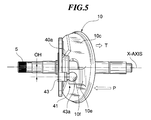
- FIG. 5 shows a linkage and component parts associated therewith.
- FIG. 7 is a side view of a swash plate, while FIG. 8 is a front view of the same.
- FIG. 9 shows distribution of compression reaction forces and tensile reaction forces acting on the swash plate.
- FIG. 10 shows the relationship between the piston stroke and torsion moment, which changes when the linkage is offset.
- the variable capacity swash plate compressor has a cylinder block 1 having one end thereof secured to a rear head 3 via a valve plate 2 and the other end thereof secured to a front head 4.
- the cylinder block 1 has a plurality of cylinder bores 6 axially extending therethrough at predetermined circumferential intervals about a drive shaft 5.
- Each cylinder bore 6 has a piston 7 slidably received therein.
- the front head 4 defines a crankcase 8 in which a swash plate 10 is contained.
- the swash plate 10 is driven by and rotates in unison with the drive shaft 5.
- a plurality of shoes 50 on each of which pivots one end 11a, spherical in shape, of a corresponding connecting rod 11 are retained on a sliding surface 10a of the swash plate 10 by a retainer 53.
- the retainer 53 is mounted on a boss 10b in the swash plate 10 and is supported or held by a retainer support plate (retainer-holding member) 55.
- the other end of the connecting rod 11 is secured to the corresponding piston.
- Each of the shoes 50 is comprised of a first support member 51 for slidably supporting a front-side surface of the one spherical end lla of the corresponding connecting rod 11 such that the one spherical end 11a of the connecting rod 11 is relatively rotatable with respect to the first support member 51 and a second support member 52 for slidably supporting or retaining a rear-side surface of the one spherical end 11a of the same such that the rear-side surface of the one end 11a of the same is relatively rotatable with respect to the second support member 52.
- the valve plate 2 is formed with refrigerant outlet ports 16 for each communicating between a compression chamber within a corresponding one of the cylinder bores and the discharge chamber 12 and refrigerant inlet ports 15 for each communicating between a compression chamber within a corresponding one of the cylinder bores 6 and the discharge chamber 12.
- the refrigerant outlet ports 16 and the refrigerant inlet ports 15 are arranged at predetermined circumferential intervals, respectively, about the drive shaft 5.
- the refrigerant outlet ports 16 are opened and closed by respective discharge valves 17 formed as a unitary member.
- the unitary member of the discharge valves 17 is fixed to a rear head-side end face of the valve plate 2 by a bolt 19 and nut 20 together with a valve stopper 18.
- the refrigerant inlet ports 15 are opened and closed by respective suction valves 21 formed as a unitary member arranged between the valve plate 2 and the cylinder block 1.
- the bolt 19 has a guide hole 19a used in guiding high-pressure refrigerant gas from the discharge chamber 12 to a radial bearing 24 and a thrust bearing 25.
- a rear end of the drive shaft 5 is rotatably supported by the radial bearing 24 and the thrust bearing 25, while a front end of the drive shaft 5 is rotatably supported by a radial bearing 26.
- a communication passage 31 is formed between the suction chamber 13 and the crankcase 8 for communication therebetween, and a pressure control valve 32 is provided at an intermediate portion of the communication passage 31 for controlling pressure within the suction chamber 13 and pressure within the crankcase 8.
- the drive shaft 5 has a thrust flange (rotating member) 40 rigidly fitted on a front portion thereof for transmitting torque from the drive shaft 5 to the swash plate 10.
- the thrust flange 40 is rotatably supported on an inner wall of the front head 4 by a thrust bearing 33.
- the thrust flange 40 and the swash plate 10 are connected with each other via a linkage (connecting means) 41.
- the swash plate 10 can tilt with respect to an imaginary plane perpendicular to the drive shaft 5.
- the linkage 41 is comprised of a bracket 10e formed on a front surface 10c of the swash plate 10, a linear guide groove 10f formed in the bracket 10e, and a rod 43 screwed into a swash plate-side surface 40a of the thrust flange 40.
- the longitudinal axis of the guide groove 10f is inclined at a predetermined angle with respect to the front surface 10c of the swash plate 10.
- the rod 43 has one spherical end 43a thereof slidably fitted in the guide groove 10f.
- the swash plate 10 has a central through hole 9 through which the drive shaft 5 extends.
- the swash plate 10 is axially slidably fitted to the drive shaft 5 in a tiltable manner, i.e. such that its angle with respect to the imaginary plane perpendicular to the drive shaft 5 may be varied.
- On the drive shaft 5 is fitted a coil spring 44 between the thrust flange 40 and the swash plate 10 to urge the swash plate 10 toward the cylinder block 1.
- the drive shaft 5 has a stopper 45 fitted thereon, and a coil spring 47 is fitted on the drive shaft 5 between the stopper 45 and the swash plate 10 to urge the swash plate 10 toward the thrust flange 40.
- approximately half of the outer periphery (compressing piston-side area) of the swash plate 10 receives compression reaction forces P from the compressing pistons 7, while the other approximately half of the outer periphery (suction piston-side area) of the same receives tensile reaction forces T from the pistons during the suction stroke 7.
- the upper half of the outer periphery of the swash plate 10 with respect to the axis (X-axis) of the drive shaft 5 is the suction piston-side area, while the lower half of the outer periphery of the same is the compressing piston-side area.
- the left half of the swash plate 10 with respect to the axis (X-axis) of the drive shaft 5 is the suction piston-side area, while the right half of the same is the compressing piston-side area
- the left half of the outer periphery of the swash plate 10 with respect to a Y-axis orthogonal to the axis (X-axis) of the drive shaft 5 is the suction piston-side area, while the right half of the outer periphery of the same is the compressing piston-side area.
- the linkage 41 is offset (by an offset amount OH) toward the compressing piston-side area. More specifically, the guide groove 10f formed in the swash plate 10 and the rod 43 having the spherical end 43a fitted in the guide groove 10f, both of which are essential parts of the linkage 41, are not located at a boundary between the suction piston-side area and the compressing piston-side area, but shifted toward the compressing piston-side area by a predetermined amount (offset amount).
- a balance weight W is shifted, as shown in FIG. 8, in a direction away from the guide groove 10f (i.e. from a location illustrated by a full line to a location illustrated by a two-dot chain line), so as to maintain a balance of rotation of the swash plate 10.
- variable capacity swash plate compressor constructed as above
- Torque from an engine, not shown, installed on an automotive vehicle, not shown, is transmitted to the drive shaft 5 to rotate the same.
- Torque from the drive shaft 5 is transmitted to the swash plate 10 via the thrust flange 40 and the linkage 41 to cause rotation of the swash plate 10.
- the suction valve 21 opens to draw low-pressure refrigerant gas from the suction chamber 13 into the compression chamber within the cylinder bore 6.
- the discharge valve 17 opens to deliver high-pressure refrigerant gas from the compression chamber to the discharge chamber 12.
- the pressure control valve 32 opens the communication passage 31, whereby the pressure within the crankcase 8 is lowered to increase the inclination of the swash plate 10. As a result, the length of stroke of the piston 7 is increased to increase the delivery quantity or capacity of the compressor. In the meantime, the spherical end 43a of the rod 43 of the linkage 41 slides along the guide groove 10f to the other end of the same.
- the swash plate 10 When the piston 7 is in linear reciprocating motion, the swash plate 10 always receives compression reaction forces P from pistons 7 during the compression stroke, i.e. forces of the pistons 7 during the compression stroke acting to push the swash plate 10 as well as tensile reaction forces T from pistons 7 during the suction stroke, i.e. forces of the pistons 7 during the suction stroke acting to pull the swash plate 10, as shown in FIGS. 5 and 7.
- the compression reaction forces act in an opposite direction to the tensile reaction forces.
- a compression reaction force F3 i.e. a component of the sum P of the compression reaction forces, acts as a negative tensile reaction force on a point L3 located on a suction piston side of the swash plate 10 with respect to a fulcrum P2, as shown in FIG. 9.
- the sum P of compression reaction forces (F1 + F2) becomes substantially equal to the sum ( ⁇ Fi + F3) of the tensile reaction forces T which assumes a negative value or acting in the same direction as the compression reaction forces.
- FIG. 10 shows that if a bore pitch is 80 mm, the value of the torsion moment Mt is much smaller when the offset amount OH is 10 to 20 mm than when the offset amount OH is equal to 0.
- variable capacity swash plate compressor of the embodiment since the linkage 41 is offset toward the compressing piston-side area, the torsion moment acting on the swash plate 10 is decreased to an extremely small value. As a result, load applied to the central through hole 9 of the swash plate 10 when the central through hole 9 is brought into engagement with the drive shaft 5 is reduced, whereby the axial movement (tilting motion) of the swash plate 10 becomes smooth. This makes it possible to improve controllability of the compressor and at the same time prevent abrasion of contact portions of the swash plate 10 and the drive shaft 5 and seizure of the compressor resulting therefrom.
- the linkage 41 is comprised of the bracket 10e, the linear guide groove 10f formed in the bracket 10e, and the rod 43 screwed into the swash plate-side surface 40a of the thrust flange 40
- the linkage may be formed by an arm formed on a front-side surface of the swash plate, a slot formed through the arm, a pair of projections formed on the swash plate-side surface of the thrust flange, and a pin extending between the two projections, for engagement with the slot.
- the linkage may have any construction so long as the linkage is capable of linking the swash plate 40 to the thrust flange 40 such that it is able to vary the angle of the swash plate 40.
Abstract
Description
Claims (3)
- A variable capacity swash plate compressor comprising a drive shaft (5), a cylinder block (1) formed therethrough with a plurality of cylinder bores (6), a plurality of pistons (7) slidably received in respective ones of the cylinder bores (6), a rotatable member (40) rigidly fitted on the drive shaft (5) for rotation in unison therewith, a swash plate (10) which is mounted on the drive shaft (5) in a manner tilted with respect to an imaginary plane perpendicular to the drive shaft (5) and is slidable axially along the drive shaft (5) and which has a sliding surface (10a) and a central through hole (9) through which the drive shaft (5) extends, connecting means (41) interposed between the rotatable member (40) and the swash plate (10), for tiltably connecting the swash plate (10) to the rotatable member (40) to cause the swash plate (10) to rotate in unison with the rotatable member (40), a plurality of shoes (50) each arranged on the sliding surface (10a) of the swash plate (10) for sliding along a circumference of the swash plate (10) as the drive shaft (5) rotates, a plurality of connecting rods (11) each of which has one end (11a) slidably connected to a corresponding one of the shoes (50) and another end (11b) connected to a corresponding one of the pistons (7), a retainer (53) mounted on the swash plate (10) such that the retainer (53) is rotatable with respect to the swash plate (10), for retaining the shoes (50), and a retainer support member (55) rigidly fitted on the swash plate (10), for slidably supporting the retainer (53), wherein a length of stroke of each of the pistons (7) changes according to an inclination of the swash plate (10),
characterised in that said connecting means (41) is offset by a predetermined amount from a boundary between a compressing piston-side area which receives compression reaction forces (P) from ones of the pistons (7) during a compression stroke and a suction piston-side area which receives tensile reaction forces (T) from ones of the pistons (7) during the suction stroke, toward the compressing piston-side area. - A variable capacity swash plate compressor according to claim 1, wherein said connecting means (41) comprises a bracket (10e) formed on a rotatable member-side surface (10c) of the swash plate (10), a linear guide groove (10f) formed in the bracket (10e) in a manner inclined with respect to the rotatable member-side surface (10c) of the swash plate (10), and a rod (43) screwed into a swash plate-side surface (40a) of the rotatable member and having one spherical end portion (43a) thereof slidably fitted in the guide groove (10f), the guide groove (10f) and the rod (43) being offset toward the compressing piston-side area by said predetermined amount.
- A variable capacity swash plate compressor according to claim 1 or 2, wherein said predetermined amount of offset is 10 to 20 mm.
Applications Claiming Priority (3)
| Application Number | Priority Date | Filing Date | Title |
|---|---|---|---|
| JP91454/97 | 1997-03-25 | ||
| JP9091454A JPH10266952A (en) | 1997-03-25 | 1997-03-25 | Variable displacement type swash plate compressor |
| JP9145497 | 1997-03-25 |
Publications (3)
| Publication Number | Publication Date |
|---|---|
| EP0867617A2 true EP0867617A2 (en) | 1998-09-30 |
| EP0867617A3 EP0867617A3 (en) | 2001-07-18 |
| EP0867617B1 EP0867617B1 (en) | 2004-01-28 |
Family
ID=14026821
Family Applications (1)
| Application Number | Title | Priority Date | Filing Date |
|---|---|---|---|
| EP98302181A Expired - Lifetime EP0867617B1 (en) | 1997-03-25 | 1998-03-24 | Variable capacity swash plate compressor |
Country Status (4)
| Country | Link |
|---|---|
| US (1) | US5931079A (en) |
| EP (1) | EP0867617B1 (en) |
| JP (1) | JPH10266952A (en) |
| DE (1) | DE69821274T2 (en) |
Cited By (8)
| Publication number | Priority date | Publication date | Assignee | Title |
|---|---|---|---|---|
| EP1052404A3 (en) * | 1999-05-13 | 2001-03-21 | Kabushiki Kaisha Toyoda Jidoshokki Seisakusho | Hinge mechanism for variable displacement compressors |
| US6425741B1 (en) * | 1999-08-05 | 2002-07-30 | Kabushiki Kaisha Toyoda Jidoshokki Seisakusho | Clutchless variable-capacity type compressor |
| FR2823261A1 (en) * | 2001-04-06 | 2002-10-11 | Sanden Corp | VARIABLE CYLINDERED AXIAL PISTON COMPRESSOR |
| WO2002093009A3 (en) * | 2001-05-16 | 2003-03-20 | Daimler Chrysler Ag | Reciprocating piston machine with a driver |
| EP1707810A1 (en) * | 2003-04-04 | 2006-10-04 | Valeo Compressor Europe GmbH | Axial piston compressor, in particular CO2 compressor for car air-conditioning apparatus |
| WO2007019903A1 (en) * | 2005-08-18 | 2007-02-22 | Valeo Compressor Europe Gmbh | Axial piston compressor |
| KR20140004367A (en) * | 2012-07-02 | 2014-01-13 | 학교법인 두원학원 | Variable displacement swash plate type compressor |
| CN104254690A (en) * | 2012-04-25 | 2014-12-31 | 三电有限公司 | Variable-capacity compressor and method for manufacturing same |
Families Citing this family (9)
| Publication number | Priority date | Publication date | Assignee | Title |
|---|---|---|---|---|
| KR100352877B1 (en) | 2000-06-12 | 2002-09-16 | 한라공조주식회사 | Structure for supporting swash plate to maximum slant degree in compressor |
| US6860188B2 (en) * | 2003-06-20 | 2005-03-01 | Visteon Global Technologies, Inc. | Variable displacement compressor hinge mechanism |
| JP2006242120A (en) * | 2005-03-04 | 2006-09-14 | Toyota Industries Corp | Variable displacement type swash plate compressor |
| US20080302236A1 (en) * | 2005-03-09 | 2008-12-11 | Calsonic Kansei Corporation | Variable Displacement Compressor |
| JP2006250057A (en) * | 2005-03-11 | 2006-09-21 | Sanden Corp | Variable displacement swash plate type compressor |
| DE202006005682U1 (en) * | 2006-04-05 | 2006-06-14 | Lincoln Gmbh & Co. Kg | Lubricant or hydraulic pump |
| KR100903037B1 (en) | 2007-10-19 | 2009-06-18 | 학교법인 두원학원 | Variable Displacement Swash Plate Type Compressor |
| JP5750802B2 (en) * | 2011-05-30 | 2015-07-22 | サンデンホールディングス株式会社 | Variable displacement compressor and method for adjusting spring biasing force acting on swash plate of variable displacement compressor |
| DE102019112237A1 (en) * | 2019-04-12 | 2020-10-15 | OET GmbH | Reciprocating compressor |
Family Cites Families (8)
| Publication number | Priority date | Publication date | Assignee | Title |
|---|---|---|---|---|
| US4533299A (en) * | 1984-05-09 | 1985-08-06 | Diesel Kiki Co., Ltd. | Variable capacity wobble plate compressor with prompt capacity control |
| US4815943A (en) * | 1986-10-01 | 1989-03-28 | Hitachi, Ltd. | Variable displacement wobble plate compressor with capacity control valve |
| US4815358A (en) * | 1988-01-27 | 1989-03-28 | General Motors Corporation | Balanced variable stroke axial piston machine |
| JP2626292B2 (en) * | 1991-03-30 | 1997-07-02 | 株式会社豊田自動織機製作所 | Variable capacity swash plate compressor |
| JP3125952B2 (en) * | 1993-04-08 | 2001-01-22 | 株式会社豊田自動織機製作所 | Variable capacity swash plate compressor |
| JPH08338362A (en) * | 1995-06-08 | 1996-12-24 | Toyota Autom Loom Works Ltd | Variable displacement type swash plate type compressor |
| JPH09137775A (en) * | 1995-09-14 | 1997-05-27 | Calsonic Corp | Capacity variable swash plate type compressor |
| JPH10213064A (en) * | 1997-01-31 | 1998-08-11 | Zexel Corp | Variable capacity swash plate type compressor |
-
1997
- 1997-03-25 JP JP9091454A patent/JPH10266952A/en not_active Withdrawn
-
1998
- 1998-03-17 US US09/042,924 patent/US5931079A/en not_active Expired - Fee Related
- 1998-03-24 DE DE1998621274 patent/DE69821274T2/en not_active Expired - Fee Related
- 1998-03-24 EP EP98302181A patent/EP0867617B1/en not_active Expired - Lifetime
Non-Patent Citations (1)
| Title |
|---|
| None |
Cited By (11)
| Publication number | Priority date | Publication date | Assignee | Title |
|---|---|---|---|---|
| EP1052404A3 (en) * | 1999-05-13 | 2001-03-21 | Kabushiki Kaisha Toyoda Jidoshokki Seisakusho | Hinge mechanism for variable displacement compressors |
| US6474955B1 (en) | 1999-05-13 | 2002-11-05 | Kabushiki Kaisha Toyoda Jidoshokki Seisakusho | Hinge mechanism for variable displacement compressors |
| US6425741B1 (en) * | 1999-08-05 | 2002-07-30 | Kabushiki Kaisha Toyoda Jidoshokki Seisakusho | Clutchless variable-capacity type compressor |
| FR2823261A1 (en) * | 2001-04-06 | 2002-10-11 | Sanden Corp | VARIABLE CYLINDERED AXIAL PISTON COMPRESSOR |
| WO2002093009A3 (en) * | 2001-05-16 | 2003-03-20 | Daimler Chrysler Ag | Reciprocating piston machine with a driver |
| US7144227B2 (en) | 2001-05-16 | 2006-12-05 | Daimlerchrysler Ag | Reciprocating-piston machine with a driver |
| EP1707810A1 (en) * | 2003-04-04 | 2006-10-04 | Valeo Compressor Europe GmbH | Axial piston compressor, in particular CO2 compressor for car air-conditioning apparatus |
| WO2007019903A1 (en) * | 2005-08-18 | 2007-02-22 | Valeo Compressor Europe Gmbh | Axial piston compressor |
| CN104254690A (en) * | 2012-04-25 | 2014-12-31 | 三电有限公司 | Variable-capacity compressor and method for manufacturing same |
| CN104254690B (en) * | 2012-04-25 | 2016-08-24 | 三电控股株式会社 | Variable displacement compressor and manufacture method thereof |
| KR20140004367A (en) * | 2012-07-02 | 2014-01-13 | 학교법인 두원학원 | Variable displacement swash plate type compressor |
Also Published As
| Publication number | Publication date |
|---|---|
| EP0867617A3 (en) | 2001-07-18 |
| EP0867617B1 (en) | 2004-01-28 |
| DE69821274D1 (en) | 2004-03-04 |
| DE69821274T2 (en) | 2004-11-18 |
| JPH10266952A (en) | 1998-10-06 |
| US5931079A (en) | 1999-08-03 |
Similar Documents
| Publication | Publication Date | Title |
|---|---|---|
| US5540559A (en) | Variable capacity swash-plate type compressor | |
| EP0867617B1 (en) | Variable capacity swash plate compressor | |
| US5259736A (en) | Swash plate type compressor with swash plate hinge coupling mechanism | |
| US5615599A (en) | Guiding mechanism for reciprocating piston of piston-type compressor | |
| US5644968A (en) | Variable capacity swash plate type compressor with an improved hinge unit for inclinably supporting a swash plate | |
| US7972118B2 (en) | Variable capacity compressor | |
| US6010313A (en) | Single-headed piston type compressor | |
| EP0809024B1 (en) | Reciprocating pistons of piston type compressor | |
| EP1148241A2 (en) | Hinge mechanism for a variable displacement compressor | |
| EP0881386B2 (en) | Swash plate compressor | |
| US6604447B2 (en) | Swash plate-type variable displacement compressor | |
| US6474955B1 (en) | Hinge mechanism for variable displacement compressors | |
| EP0853199B1 (en) | Variable capacity swash plate compressor | |
| US6044751A (en) | Variable displacement compressor | |
| US20050265855A1 (en) | Piston type compressor | |
| US5882179A (en) | Compressor with bearing between the drive shaft and the swash-plate boss | |
| EP0856662A2 (en) | Variable capacity swash plate compressor | |
| US5980216A (en) | Variable capacity swash plate compressor having a retainer support plate | |
| US20020040638A1 (en) | Swash plate compressor having variable capacity | |
| EP1275846B1 (en) | Hinge for a swash plate | |
| US5950520A (en) | Swash plate compressor | |
| EP0856663A2 (en) | Variable capacity swash plate compressor | |
| US6368073B1 (en) | Swash plate compressor | |
| KR100519745B1 (en) | Variable Displacement Swash Plate Type Compressor | |
| JP2000170652A (en) | Variable displacement swash plate compressor |
Legal Events
| Date | Code | Title | Description |
|---|---|---|---|
| PUAI | Public reference made under article 153(3) epc to a published international application that has entered the european phase |
Free format text: ORIGINAL CODE: 0009012 |
|
| AK | Designated contracting states |
Kind code of ref document: A2 Designated state(s): DE FR GB |
|
| AX | Request for extension of the european patent |
Free format text: AL;LT;LV;MK;RO;SI |
|
| RAP1 | Party data changed (applicant data changed or rights of an application transferred) |
Owner name: ZEXEL VALEO CLIMATE CONTROL CORPORATION |
|
| PUAL | Search report despatched |
Free format text: ORIGINAL CODE: 0009013 |
|
| AK | Designated contracting states |
Kind code of ref document: A3 Designated state(s): AT BE CH DE DK ES FI FR GB GR IE IT LI LU MC NL PT SE |
|
| AX | Request for extension of the european patent |
Free format text: AL;LT;LV;MK;RO;SI |
|
| 17P | Request for examination filed |
Effective date: 20010703 |
|
| AKX | Designation fees paid |
Free format text: DE FR GB |
|
| GRAP | Despatch of communication of intention to grant a patent |
Free format text: ORIGINAL CODE: EPIDOSNIGR1 |
|
| GRAS | Grant fee paid |
Free format text: ORIGINAL CODE: EPIDOSNIGR3 |
|
| GRAA | (expected) grant |
Free format text: ORIGINAL CODE: 0009210 |
|
| AK | Designated contracting states |
Kind code of ref document: B1 Designated state(s): DE FR GB |
|
| REG | Reference to a national code |
Ref country code: GB Ref legal event code: FG4D |
|
| REF | Corresponds to: |
Ref document number: 69821274 Country of ref document: DE Date of ref document: 20040304 Kind code of ref document: P |
|
| PG25 | Lapsed in a contracting state [announced via postgrant information from national office to epo] |
Ref country code: GB Free format text: LAPSE BECAUSE OF NON-PAYMENT OF DUE FEES Effective date: 20040428 |
|
| ET | Fr: translation filed | ||
| PLBE | No opposition filed within time limit |
Free format text: ORIGINAL CODE: 0009261 |
|
| STAA | Information on the status of an ep patent application or granted ep patent |
Free format text: STATUS: NO OPPOSITION FILED WITHIN TIME LIMIT |
|
| GBPC | Gb: european patent ceased through non-payment of renewal fee |
Effective date: 20040428 |
|
| 26N | No opposition filed |
Effective date: 20041029 |
|
| PGFP | Annual fee paid to national office [announced via postgrant information from national office to epo] |
Ref country code: DE Payment date: 20070322 Year of fee payment: 10 |
|
| PGFP | Annual fee paid to national office [announced via postgrant information from national office to epo] |
Ref country code: FR Payment date: 20070308 Year of fee payment: 10 |
|
| REG | Reference to a national code |
Ref country code: FR Ref legal event code: ST Effective date: 20081125 |
|
| PG25 | Lapsed in a contracting state [announced via postgrant information from national office to epo] |
Ref country code: DE Free format text: LAPSE BECAUSE OF NON-PAYMENT OF DUE FEES Effective date: 20081001 |
|
| PG25 | Lapsed in a contracting state [announced via postgrant information from national office to epo] |
Ref country code: FR Free format text: LAPSE BECAUSE OF NON-PAYMENT OF DUE FEES Effective date: 20080331 |