EP0865851A1 - Clamping device for a cutting insert - Google Patents
Clamping device for a cutting insert Download PDFInfo
- Publication number
- EP0865851A1 EP0865851A1 EP98104920A EP98104920A EP0865851A1 EP 0865851 A1 EP0865851 A1 EP 0865851A1 EP 98104920 A EP98104920 A EP 98104920A EP 98104920 A EP98104920 A EP 98104920A EP 0865851 A1 EP0865851 A1 EP 0865851A1
- Authority
- EP
- European Patent Office
- Prior art keywords
- insert
- roller
- slot
- recess
- clamp
- Prior art date
- Legal status (The legal status is an assumption and is not a legal conclusion. Google has not performed a legal analysis and makes no representation as to the accuracy of the status listed.)
- Granted
Links
- 238000000034 method Methods 0.000 claims 2
- 238000009434 installation Methods 0.000 description 3
- 229910000760 Hardened steel Inorganic materials 0.000 description 1
- 229910000997 High-speed steel Inorganic materials 0.000 description 1
- 229910000831 Steel Inorganic materials 0.000 description 1
- 229910001315 Tool steel Inorganic materials 0.000 description 1
- 230000000694 effects Effects 0.000 description 1
- 239000010959 steel Substances 0.000 description 1
Images



Classifications
-
- B—PERFORMING OPERATIONS; TRANSPORTING
- B23—MACHINE TOOLS; METAL-WORKING NOT OTHERWISE PROVIDED FOR
- B23B—TURNING; BORING
- B23B27/00—Tools for turning or boring machines; Tools of a similar kind in general; Accessories therefor
- B23B27/04—Cutting-off tools
-
- B—PERFORMING OPERATIONS; TRANSPORTING
- B23—MACHINE TOOLS; METAL-WORKING NOT OTHERWISE PROVIDED FOR
- B23B—TURNING; BORING
- B23B2205/00—Fixation of cutting inserts in holders
- B23B2205/02—Fixation using an elastically deformable clamping member
-
- B—PERFORMING OPERATIONS; TRANSPORTING
- B23—MACHINE TOOLS; METAL-WORKING NOT OTHERWISE PROVIDED FOR
- B23B—TURNING; BORING
- B23B2265/00—Details of general geometric configurations
- B23B2265/12—Eccentric
-
- Y—GENERAL TAGGING OF NEW TECHNOLOGICAL DEVELOPMENTS; GENERAL TAGGING OF CROSS-SECTIONAL TECHNOLOGIES SPANNING OVER SEVERAL SECTIONS OF THE IPC; TECHNICAL SUBJECTS COVERED BY FORMER USPC CROSS-REFERENCE ART COLLECTIONS [XRACs] AND DIGESTS
- Y10—TECHNICAL SUBJECTS COVERED BY FORMER USPC
- Y10T—TECHNICAL SUBJECTS COVERED BY FORMER US CLASSIFICATION
- Y10T407/00—Cutters, for shaping
- Y10T407/22—Cutters, for shaping including holder having seat for inserted tool
- Y10T407/2272—Cutters, for shaping including holder having seat for inserted tool with separate means to fasten tool to holder
- Y10T407/228—Rotatable cam clamp element
-
- Y—GENERAL TAGGING OF NEW TECHNOLOGICAL DEVELOPMENTS; GENERAL TAGGING OF CROSS-SECTIONAL TECHNOLOGIES SPANNING OVER SEVERAL SECTIONS OF THE IPC; TECHNICAL SUBJECTS COVERED BY FORMER USPC CROSS-REFERENCE ART COLLECTIONS [XRACs] AND DIGESTS
- Y10—TECHNICAL SUBJECTS COVERED BY FORMER USPC
- Y10T—TECHNICAL SUBJECTS COVERED BY FORMER US CLASSIFICATION
- Y10T407/00—Cutters, for shaping
- Y10T407/22—Cutters, for shaping including holder having seat for inserted tool
- Y10T407/2272—Cutters, for shaping including holder having seat for inserted tool with separate means to fasten tool to holder
- Y10T407/2282—Cutters, for shaping including holder having seat for inserted tool with separate means to fasten tool to holder including tool holding clamp and clamp actuator
- Y10T407/2284—Wedge clamp element
-
- Y—GENERAL TAGGING OF NEW TECHNOLOGICAL DEVELOPMENTS; GENERAL TAGGING OF CROSS-SECTIONAL TECHNOLOGIES SPANNING OVER SEVERAL SECTIONS OF THE IPC; TECHNICAL SUBJECTS COVERED BY FORMER USPC CROSS-REFERENCE ART COLLECTIONS [XRACs] AND DIGESTS
- Y10—TECHNICAL SUBJECTS COVERED BY FORMER USPC
- Y10T—TECHNICAL SUBJECTS COVERED BY FORMER US CLASSIFICATION
- Y10T407/00—Cutters, for shaping
- Y10T407/22—Cutters, for shaping including holder having seat for inserted tool
- Y10T407/2272—Cutters, for shaping including holder having seat for inserted tool with separate means to fasten tool to holder
- Y10T407/2282—Cutters, for shaping including holder having seat for inserted tool with separate means to fasten tool to holder including tool holding clamp and clamp actuator
- Y10T407/2286—Resiliently biased clamp jaw
-
- Y—GENERAL TAGGING OF NEW TECHNOLOGICAL DEVELOPMENTS; GENERAL TAGGING OF CROSS-SECTIONAL TECHNOLOGIES SPANNING OVER SEVERAL SECTIONS OF THE IPC; TECHNICAL SUBJECTS COVERED BY FORMER USPC CROSS-REFERENCE ART COLLECTIONS [XRACs] AND DIGESTS
- Y10—TECHNICAL SUBJECTS COVERED BY FORMER USPC
- Y10T—TECHNICAL SUBJECTS COVERED BY FORMER US CLASSIFICATION
- Y10T407/00—Cutters, for shaping
- Y10T407/22—Cutters, for shaping including holder having seat for inserted tool
- Y10T407/2272—Cutters, for shaping including holder having seat for inserted tool with separate means to fasten tool to holder
- Y10T407/2282—Cutters, for shaping including holder having seat for inserted tool with separate means to fasten tool to holder including tool holding clamp and clamp actuator
- Y10T407/2286—Resiliently biased clamp jaw
- Y10T407/2288—Integral with holder
Definitions
- the present invention relates to a clamping device for a cutting insert, in particular for an insert for the turning of grooves and parting, in accordance with claim 1.
- Cutting inserts for, for example, grooving and parting are clamped in holders of the blade type, in order to achieve narrow widths of cut.
- blade type also includes slitting cutters and circular saw blades.
- a clamping device for a cutting insert in a holder of blade type including a cutting insert which can be clamped in a slot in the blade.
- the cutting insert is clamped by the spring action which is created by deflection of a clamping finger which is an integral part of the holder.
- a special installation tool is used which consists of a rod with two pins in the one end surface. Admittedly this device functions satisfactorily but it nevertheless suffers from certain drawbacks.
- EP-A-259 847 a blade holder with a slot for receiving the cutting insert is described, plus an additional slot for the mounting of a clamping screw, which when activated forces the blade part between said two slots and presses it against the cutting insert, whereby the insert is clamped. Also here a certain wear occurs when installing the cutting insert into and removing the cutting insert from the slot in which the insert is to sit. Furthermore the clamping screw can cause certain problems, by limiting the amount of play and giving inadequate clamping force.
- the prime purpose of the present invention is consequently to, as far as is ever possible, avoid wear of the holder abutment surfaces which work against the cutting insert.
- Another purpose of the present invention is to maintain a large clamping force for the cutting insert during a long period of time.
- Yet another purpose of the present invention is to attain the most exact positioning of the the cutting insert possible when clamping, with distinct abutment against a rear abutment surface in the slot which receives the insert.
- FIG 1 a blade holder in general is designated with 1.
- This blade holder like those in the remaining figures, can be of any length desired, which is illustrated in section 2.
- a recess or a slot 3 is provided, in which a cutting insert 4 can be inserted and clamped.
- the blade holder comprises an integrated upper, somewhat springy clamp 5, which in turn includes a tensioning roller 6, which is brought to press onto and hence, firmly clamp the cutting insert 4.
- a double headed insert 4 is shown in the figure, which feature a cutting edge 7,7' in either direction. This improves cutting economy by allowing the insert to be turned half a revolution when the one edge is worn out.
- the invention is not however limited to the use of double-edged cutting inserts, but even inserts with only one cutting edge can be taken into consideration.
- the cutting insert can exhibit a substantially V-shaped groove 9 on its lower side, which is brought to abut against a corresponding, substantially V-shaped rib 10 in the slot. Corresponding ribs and grooves can also exist on the short sides 11 of the cutting insert and abutment 8 of the slot.
- These cooperating ribs and grooves can also is inverted, such that the ribs are replaced by grooves and grooves replacedby ribs.
- the cross section need not be substantially V-shaped but can for example be formed as a segment of a circle.
- the abutment surface 8 and the side of the insert 11 can also be wholly plane.
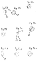
- the tensioning roller 6 in figs1-3 has the shape shown in fig 10a-c. In principle it has the form of two truncated identically shaped cones, the bottom surfaces of which abut against each other, wherein a segment is cut away, such that a planar surface 12 is created. Further the tensioning roller features a central recess 19, to enable the roller to be rotated with a suitable tool, such as an allan key.
- the two side surfaces of the conical parts 13 are brought to abut partly against an opposing, rounded, essentially V-shaped surface in the recess 14 the of the upper clamp, and partly against an essentially V-shaped groove 15 (see. fig 5) on the upper side of the cutting insert.
- a tensioning roller with a shape according to fig 10a-c can also be brought into engagement with cutting inserts with other shapes than those shown in fig 1, 2 and 5. Consequently the upper side of the cutting insert can exhibit two cavities 16 in accordance with figs 6 and 7, wherein the cross section of said cavities essentially agrees with that of the tensioning roller. Naturally only one cavity is required for an insert with one cutting edge. Further the same type of tensioning roller can be brought into engagement with cutting inserts according to figs, 8 and 9. The upper side of these inserts slopes from both ends downwards towards a lower part at the centre of the upper side. In addition the upper side shows a substantially V-shaped groove, the cross section of which is in agreement with the shape of the tensioning roller.
- the roller When the roller is to be installed it must be rotated so that the planar surface 12 is in principle vertical, i.e. at a right angle to the upper limiting surface 20 of slot 3. Subsequently the roller is pressed into recess 14 from below (see figs 3 and 4), which can be accomplished completely without resistance or by overcoming a light click action. Once the roller has been put in position in the recess 14, the roller can be rotated in either direction so that the planar surface 12 takes up a position other than the vertical, whereby the the roller is locked in recess 14.
- the tensioning roller When an insert is to be installed in the insert seat, the tensioning roller is first rotated so that the planar surface 12 is brought to lie straight downwards, that is to say substantially planar parallel with surface 20. Thereby the roller goes free from the insert 4 which can then be moved into contact with contact surface 8. The tensioning roller is then rotated so that its side surfaces 13 are brought to press against the groove 15 in the upper side of the insert. By rotating the insert anti-clockwise in figure 2, the insert is also brought into distinct contact with the rear contact surface 8. When the insert is to be released the tensioning roller is turned clockwise as seen in fig.2, until the planar surface 12, faces downwards, towards the upper surface of the insert. Thereby a play between the insert and roller is reestablished, whereby the insert is free and can be pulled out of the slot. It should also be noted that, no contact occurs between the insert and the upper limiting surface 20, of the slot.
- the tensioning roller can even be given other shapes than those seen in figs, 10a-c, whereby the only limitations are that the roller is locked axially and in the recess 14, which is matched to the shape of the roller, plus that the roller can clamp an insert. Therefore a tensioning roller with a substantially V-formed groove around the surface on the sides of the conical parts 21 is shown in figs. 11a-c, whereby the recess for the clamp 14, and the upper side of the insert have corresponding ribs. The tensioning roller will come to lie against the insert and the recess with its two flank surfaces 22, in this situation the middle surface 23, of the insert is free of contact with any other surface.
- the roller can be designed with a central, groove 24 (see figs 12a-c) substantially with the shape of a segment of a circle in its casing surface. Thereby the insert respectively the recess can be shaped with the corresponding central, rounded rib.
- Tensioning rollers according to figs. 10-12 are, if one excepts the planar surface 12, rotationally symmetrical. In order to facilitate clamping and give a gradually increasing counter torque for the tensioning roller, they can however be shaped with an asymmetrical contact surface, for example with increasing radius. Thus a tensioning roller is shown with chamfered side walls of the conical sections in figs. 13 a, b, which flow out into clamping parts 26, the contact of which against the upper side of the insert means maximum clamping force.
- Figure 14 shows a tensioning roller with a "tension intensifying" part 27 which gives a step free clamping from a tension free condition, when the planar contact surface 12 faces towards the insert, to the position where maximum clamping effect is achieved when the round contact surface 28 has constant and maximum radius.
- Figures 15 a, b illustrate a further design with chamfered surfaces on the side surfaces of the conical areas, more specifically three chamfered surfaces 29. These are slightly convex and have have their parts with the smallest radius at the middle of the chamfered surface. They connect with each other via part 30 at the maximum radius. When the part 30 has been rotated so that it lies in contact with the insert, maximum clamping force has been achieved. At the part with minimum radius the roller runs free from the insert.
- the actual blade holder is normally produced in a suitable steel, such as tool steel.
- the roller can be manufactured in e.g. hardened steel, high speed steel or cemented carbide.
Landscapes
- Engineering & Computer Science (AREA)
- Mechanical Engineering (AREA)
- Cutting Tools, Boring Holders, And Turrets (AREA)
- Shearing Machines (AREA)
- Automatic Assembly (AREA)
- Processing Of Stones Or Stones Resemblance Materials (AREA)
- Milling Processes (AREA)
Abstract
Description
Claims (7)
- An arrangement for the fastening of a cutting insert in a blade holder (1), in particular for the turning of grooves and parting, comprising a slot (3), which receives said insert which is limited along its upper side by a clamp (5), characterized in , that the said clamp on said over side (20), features a recess (14) which accomodates a tensioning roller (6), which is intended to press against the upper side of the insert and clamp it.
- An arrangement according to claim 1, whereby a tension roller (6) and a recess (14) are shaped with matching male and female parts which fix the roller in the axial direction.
- An arrangement according to claims 1 and 2, whereby the tensioning roller incorporates a planar surface (12), which makes possible the introduction of the roller into the recess (14) plus the free movement of the insert relative to the roller when installing the insert in the slot (3).
- An arrangement according to any of the previous claims, whereby the tensioning roller shows a rib which runs centrally around the side surfaces of the double conical part (fig. 10), a substantially V-shaped groove (fig 11), which runs centrally, or a groove with a shape matching the segment of a circle (24), which runs centrally.
- An arrangement according to any of the the previous claims, whereby the tension roller shows a surface part formed by the side walls of the conical parts with increasing radius in order to make possible step free increase of the clamping force against the insert.
- A method for the fastening of an insert in a blade holder, whereby the blade holder includes a recess or slit (3), to accomodate an insert, and said slit is limited along its upper side surfaces (20) by a clamp (5), characterized in, that a tensioning roller is arrangerd in a recess (14) in the said upper side surface (20), whereby this roller exerts a pressure against the insert and clamps it in the said slot (3).
- A method according to claim 6, whereby the tensioning roller (6), incorporates along the side walls of the conical sections a planar surface (12), which is directed towards the upper side of the insert when the insert is pushed into the slot, under which circumstances a gap exists between the roller and the insert, after which the roller is rotated so that the planar surface is directed in another direction and instead a part of the rollers round sides of the conical parts are brought to press against the upper surface of the insert, so that the insert is clamped firmly in the slot.
Applications Claiming Priority (2)
| Application Number | Priority Date | Filing Date | Title |
|---|---|---|---|
| SE9701003 | 1997-03-19 | ||
| SE9701003A SE511928C2 (en) | 1997-03-19 | 1997-03-19 | Device and method of clamping inserts |
Publications (2)
| Publication Number | Publication Date |
|---|---|
| EP0865851A1 true EP0865851A1 (en) | 1998-09-23 |
| EP0865851B1 EP0865851B1 (en) | 2000-09-20 |
Family
ID=20406226
Family Applications (1)
| Application Number | Title | Priority Date | Filing Date |
|---|---|---|---|
| EP98104920A Expired - Lifetime EP0865851B1 (en) | 1997-03-19 | 1998-03-18 | Clamping device for a cutting insert |
Country Status (7)
| Country | Link |
|---|---|
| US (1) | US5934843A (en) |
| EP (1) | EP0865851B1 (en) |
| JP (1) | JP4176862B2 (en) |
| AT (1) | ATE196438T1 (en) |
| DE (1) | DE69800313T2 (en) |
| ES (1) | ES2151754T3 (en) |
| SE (1) | SE511928C2 (en) |
Cited By (12)
| Publication number | Priority date | Publication date | Assignee | Title |
|---|---|---|---|---|
| WO2000013824A1 (en) * | 1998-09-09 | 2000-03-16 | Sandvik Aktiebolag | Cutting insert for grooving operations |
| WO2000045981A1 (en) * | 1999-02-02 | 2000-08-10 | Sandvik Aktiebolag | Cutting tool for parting and similar operations |
| EP1083017A1 (en) * | 1999-09-09 | 2001-03-14 | Plansee Tizit Aktiengesellschaft | Rotary cutting tool |
| DE19948911A1 (en) * | 1999-10-11 | 2001-05-23 | Volker Neumann | Holder for a cutting insert |
| WO2004071695A1 (en) * | 2003-02-14 | 2004-08-26 | Sumitomo Electric Industries, Ltd. | Edge replacement tip and cutting tool using the same |
| WO2008038262A1 (en) * | 2006-09-28 | 2008-04-03 | Iscar Ltd. | Cutting tool having cutting insert secured by non-penetrating abutment of a threaded fastener |
| WO2011159119A3 (en) * | 2010-06-17 | 2012-04-19 | Taegutec Ltd. | Cutting insert and tool holder for mounting the cutting insert |
| US9168588B2 (en) | 2012-11-29 | 2015-10-27 | Kennametal Inc. | Cutting insert having a coolant duct |
| US9242300B2 (en) | 2012-09-04 | 2016-01-26 | Kennametal Inc. | Tool holder for groove cutting tool, groove insert and groove cutting tool |
| US9586265B2 (en) | 2012-03-09 | 2017-03-07 | Kennametal Inc | Groove insert, clamping holder for a groove insert and groove cutting tool |
| EP1558431B1 (en) | 2002-10-18 | 2017-05-03 | Kennametal Inc. | Metal cutting insert with chip breaking surfaces |
| EP3421159A1 (en) * | 2017-06-27 | 2019-01-02 | Walter Ag | Double ended cutting insert for parting |
Families Citing this family (34)
| Publication number | Priority date | Publication date | Assignee | Title |
|---|---|---|---|---|
| SE509339C2 (en) * | 1994-12-08 | 1999-01-11 | Seco Tools Ab | Tools and cutters for chip separating machining |
| DE19807498A1 (en) * | 1998-02-21 | 1999-09-02 | Horn P Hartmetall Werkzeugfab | Holder for cutting tool inserts |
| IL127192A (en) * | 1998-11-22 | 2008-06-05 | Gideon Barazani | Resilient clamping mechanism for inserts |
| US6929426B2 (en) * | 2003-02-19 | 2005-08-16 | Kennametal Inc. | Indexable cutting tool |
| SE529021C2 (en) * | 2004-09-21 | 2007-04-10 | Seco Tools Ab | Cutting Tools |
| JP4770297B2 (en) | 2004-12-16 | 2011-09-14 | 三菱マテリアル株式会社 | Cutting insert clamping mechanism and cutting insert |
| JP4802745B2 (en) * | 2006-02-08 | 2011-10-26 | 三菱マテリアル株式会社 | Cutting insert and insert detachable cutting tool |
| US8328477B2 (en) * | 2006-03-02 | 2012-12-11 | Milwaukee Electric Tool Corporation | Cutting tool |
| US7661911B2 (en) * | 2006-03-02 | 2010-02-16 | Milwaukee Electric Tool Corporation | Cutting tool |
| USD605672S1 (en) * | 2007-03-01 | 2009-12-08 | Milwaukee Electric Tool Corporation | Cutting blade |
| AT505360B1 (en) * | 2007-05-24 | 2011-09-15 | Boehlerit Gmbh & Co Kg | CUTTING TOOL WITH DETACHABLE CUTTING PLATES |
| US20090071223A1 (en) * | 2007-09-19 | 2009-03-19 | Rogers Bryan L | Staged Tooling Technology |
| JP5157660B2 (en) * | 2008-06-09 | 2013-03-06 | 三菱マテリアル株式会社 | Cutting insert and insert detachable cutting tool |
| DE102012111240A1 (en) * | 2012-11-21 | 2014-05-22 | Hartmetall-Werkzeugfabrik Paul Horn Gmbh | Machining tool |
| US9500038B2 (en) | 2013-02-01 | 2016-11-22 | Milwaukee Electric Tool Corporation | Auger bit with replaceable cutting bit |
| US9120239B2 (en) | 2013-02-21 | 2015-09-01 | Iscar, Ltd. | Cutting tool and cutting insert having insert key recesses for extracting and mounting therein |
| EP2810729A1 (en) * | 2013-06-05 | 2014-12-10 | Boehlerit GmbH & Co. KG. | Tool with cutting plates, adapter with cutting plates and use of such a tool |
| US9579727B2 (en) | 2014-05-28 | 2017-02-28 | Kennametal Inc. | Cutting assembly with cutting insert having enhanced coolant delivery |
| US10010942B2 (en) * | 2016-06-20 | 2018-07-03 | Iscar, Ltd. | Cutting tool and cutting insert having a deep blind opening |
| USD880547S1 (en) | 2017-11-30 | 2020-04-07 | Illinois Tool Works Inc. | Cutting insert |
| USD836143S1 (en) * | 2017-11-30 | 2018-12-18 | Illinois Tool Works Inc. | Cutting insert holder |
| USD912708S1 (en) | 2017-11-30 | 2021-03-09 | Illinois Tool Works Inc. | Cutting insert |
| US10583495B1 (en) * | 2018-09-17 | 2020-03-10 | Iscar, Ltd. | Swiss turning insert, swiss tool holder and assembly |
| US12036616B2 (en) * | 2019-05-13 | 2024-07-16 | Kyocera Corporation | Clamping member, machine tool, and method for manufacturing machined product |
| JP2022055501A (en) * | 2020-09-29 | 2022-04-08 | 日本特殊陶業株式会社 | Cutting insert and cutting tool |
| KR102567172B1 (en) * | 2021-04-06 | 2023-08-17 | 코오롱데크컴퍼지트 주식회사 | Machining apparatus of aerodynamic composite |
| US12109632B2 (en) * | 2021-09-22 | 2024-10-08 | Iscar, Ltd. | Tool holder with upper and lower jaws defining an insert receiving pocket and cutting tool |
| US11806793B2 (en) | 2021-11-03 | 2023-11-07 | Iscar, Ltd. | Cutting insert having laterally spaced apart, longitudinally extending wedge abutment surfaces, tool holder and cutting tool |
| USD1073753S1 (en) * | 2022-02-24 | 2025-05-06 | Sumitomo Electric Hardmetal Corp. | Cutting tool |
| US12172219B2 (en) | 2022-03-16 | 2024-12-24 | Iscar, Ltd. | Cutting insert having grooved top and bottom abutment surfaces with inner and outer pairs of wedge angles, and cutting tool |
| US11766724B1 (en) | 2022-03-16 | 2023-09-26 | Iscar, Ltd. | Cutting tool and tool holder having separate rear abutment and wedged rear stopper surfaces |
| US12275078B2 (en) | 2022-05-03 | 2025-04-15 | Iscar, Ltd. | Rotationally asymmetric double-ended grooving cutting insert, insert holder and cutting tool |
| USD1073755S1 (en) * | 2022-08-01 | 2025-05-06 | Sumitomo Electric Hardmetal Corp. | Cutting tool |
| US12465981B2 (en) | 2022-09-07 | 2025-11-11 | Iscar, Ltd. | Cemented carbide cutting insert for parting metal workpieces |
Citations (2)
| Publication number | Priority date | Publication date | Assignee | Title |
|---|---|---|---|---|
| US2293006A (en) * | 1941-08-20 | 1942-08-11 | John M Luers | Tool holder |
| DE3319799A1 (en) * | 1983-06-01 | 1984-12-06 | Werner 6967 Buchen Keller | Device for clamping cutting inserts in place |
Family Cites Families (7)
| Publication number | Priority date | Publication date | Assignee | Title |
|---|---|---|---|---|
| US1169594A (en) * | 1913-01-04 | 1916-01-25 | Williams J H & Co | Tool-holder. |
| US1110281A (en) * | 1913-07-17 | 1914-09-08 | Williams J H & Co | Tool-holder. |
| US3069937A (en) * | 1960-11-29 | 1962-12-25 | O K Tool Co Inc | Clamp and bit holder |
| US3798724A (en) * | 1972-07-28 | 1974-03-26 | Gorham Tool Co | Locking arrangement for cutting blade inserts |
| SE441247B (en) * | 1984-02-20 | 1985-09-23 | Seco Tools Ab | SPANISH PROCESSING TOOLS, PREFERRED TO STICKSTAL TOOLS TO SPANISH PROCESSING, PREFERRED TO STICKSTAL |
| SE452713B (en) * | 1986-04-07 | 1987-12-14 | Sandvik Ab | CUTTING TOOLS AND SHOULD BE USED IN THESE TOOLS |
| DE3635052A1 (en) * | 1986-09-10 | 1988-03-24 | Reika Werk Gmbh Maschf | TOOL FOR METAL PROCESSING LIKE BEVELING, PUNCHING, PLANNING AND MILLING |
-
1997
- 1997-03-19 SE SE9701003A patent/SE511928C2/en not_active IP Right Cessation
-
1998
- 1998-03-18 EP EP98104920A patent/EP0865851B1/en not_active Expired - Lifetime
- 1998-03-18 ES ES98104920T patent/ES2151754T3/en not_active Expired - Lifetime
- 1998-03-18 AT AT98104920T patent/ATE196438T1/en active
- 1998-03-18 DE DE69800313T patent/DE69800313T2/en not_active Expired - Lifetime
- 1998-03-19 JP JP07071498A patent/JP4176862B2/en not_active Expired - Fee Related
- 1998-03-19 US US09/044,011 patent/US5934843A/en not_active Expired - Lifetime
Patent Citations (2)
| Publication number | Priority date | Publication date | Assignee | Title |
|---|---|---|---|---|
| US2293006A (en) * | 1941-08-20 | 1942-08-11 | John M Luers | Tool holder |
| DE3319799A1 (en) * | 1983-06-01 | 1984-12-06 | Werner 6967 Buchen Keller | Device for clamping cutting inserts in place |
Cited By (16)
| Publication number | Priority date | Publication date | Assignee | Title |
|---|---|---|---|---|
| WO2000013824A1 (en) * | 1998-09-09 | 2000-03-16 | Sandvik Aktiebolag | Cutting insert for grooving operations |
| WO2000045981A1 (en) * | 1999-02-02 | 2000-08-10 | Sandvik Aktiebolag | Cutting tool for parting and similar operations |
| EP1083017A1 (en) * | 1999-09-09 | 2001-03-14 | Plansee Tizit Aktiengesellschaft | Rotary cutting tool |
| DE19948911A1 (en) * | 1999-10-11 | 2001-05-23 | Volker Neumann | Holder for a cutting insert |
| DE19948911B4 (en) * | 1999-10-11 | 2009-06-10 | Volker Neumann | Holder for an insert or holder with insert |
| DE19948911B9 (en) * | 1999-10-11 | 2010-08-05 | Volker Neumann | Holder for an insert or holder with insert |
| EP1558431B1 (en) | 2002-10-18 | 2017-05-03 | Kennametal Inc. | Metal cutting insert with chip breaking surfaces |
| WO2004071695A1 (en) * | 2003-02-14 | 2004-08-26 | Sumitomo Electric Industries, Ltd. | Edge replacement tip and cutting tool using the same |
| US8459162B2 (en) | 2003-02-14 | 2013-06-11 | Sumitomo Electric Industries, Ltd. | Edge replacement tip and cutting tool using the same |
| WO2008038262A1 (en) * | 2006-09-28 | 2008-04-03 | Iscar Ltd. | Cutting tool having cutting insert secured by non-penetrating abutment of a threaded fastener |
| WO2011159119A3 (en) * | 2010-06-17 | 2012-04-19 | Taegutec Ltd. | Cutting insert and tool holder for mounting the cutting insert |
| US9586265B2 (en) | 2012-03-09 | 2017-03-07 | Kennametal Inc | Groove insert, clamping holder for a groove insert and groove cutting tool |
| DE102012004804C5 (en) | 2012-03-09 | 2019-03-14 | Kennametal Inc. | Puncture cutting plate and lancing cutting tool |
| US9242300B2 (en) | 2012-09-04 | 2016-01-26 | Kennametal Inc. | Tool holder for groove cutting tool, groove insert and groove cutting tool |
| US9168588B2 (en) | 2012-11-29 | 2015-10-27 | Kennametal Inc. | Cutting insert having a coolant duct |
| EP3421159A1 (en) * | 2017-06-27 | 2019-01-02 | Walter Ag | Double ended cutting insert for parting |
Also Published As
| Publication number | Publication date |
|---|---|
| DE69800313T2 (en) | 2001-04-05 |
| SE9701003D0 (en) | 1997-03-19 |
| ES2151754T3 (en) | 2001-01-01 |
| US5934843A (en) | 1999-08-10 |
| JPH10315012A (en) | 1998-12-02 |
| ATE196438T1 (en) | 2000-10-15 |
| DE69800313D1 (en) | 2000-10-26 |
| SE511928C2 (en) | 1999-12-20 |
| EP0865851B1 (en) | 2000-09-20 |
| SE9701003L (en) | 1998-09-20 |
| JP4176862B2 (en) | 2008-11-05 |
Similar Documents
| Publication | Publication Date | Title |
|---|---|---|
| EP0865851B1 (en) | Clamping device for a cutting insert | |
| EP0878260A2 (en) | Tool for grooving and parting and method of manufacturing same | |
| US6234727B1 (en) | Resilient clamping mechanism for inserts | |
| EP1737596B1 (en) | Cutting tool | |
| EP0420512B1 (en) | Cutting insert and cutting tool for this insert | |
| JP4531040B2 (en) | Cutting tool and cartridge therefor | |
| US4938640A (en) | Metal cutting tool | |
| CA2436948C (en) | Cutting tool | |
| EP2066471B1 (en) | Cutting tool having cutting insert secured by non-penetrating abutment of a threaded fastener | |
| EP1013364B1 (en) | Cutting tool assembly | |
| US5803675A (en) | Holder for metal-cutting tool inserts | |
| EP1793951B1 (en) | Cutting tool | |
| CN100478126C (en) | Cutting tool head for a working tool | |
| EP0096147B1 (en) | Cutting tool and cutting insert therefor | |
| WO1993020972A1 (en) | Arcuate seat tool holders and inserts |
Legal Events
| Date | Code | Title | Description |
|---|---|---|---|
| PUAI | Public reference made under article 153(3) epc to a published international application that has entered the european phase |
Free format text: ORIGINAL CODE: 0009012 |
|
| AK | Designated contracting states |
Kind code of ref document: A1 Designated state(s): AT DE ES FR GB IT SE |
|
| AX | Request for extension of the european patent |
Free format text: AL;LT;LV;MK;RO;SI |
|
| 17P | Request for examination filed |
Effective date: 19981001 |
|
| 17Q | First examination report despatched |
Effective date: 19981215 |
|
| AKX | Designation fees paid |
Free format text: AT DE ES FR GB IT SE |
|
| RBV | Designated contracting states (corrected) |
Designated state(s): AT DE ES FR GB IT SE |
|
| GRAG | Despatch of communication of intention to grant |
Free format text: ORIGINAL CODE: EPIDOS AGRA |
|
| GRAG | Despatch of communication of intention to grant |
Free format text: ORIGINAL CODE: EPIDOS AGRA |
|
| GRAH | Despatch of communication of intention to grant a patent |
Free format text: ORIGINAL CODE: EPIDOS IGRA |
|
| GRAH | Despatch of communication of intention to grant a patent |
Free format text: ORIGINAL CODE: EPIDOS IGRA |
|
| GRAA | (expected) grant |
Free format text: ORIGINAL CODE: 0009210 |
|
| AK | Designated contracting states |
Kind code of ref document: B1 Designated state(s): AT DE ES FR GB IT SE |
|
| REF | Corresponds to: |
Ref document number: 196438 Country of ref document: AT Date of ref document: 20001015 Kind code of ref document: T |
|
| REF | Corresponds to: |
Ref document number: 69800313 Country of ref document: DE Date of ref document: 20001026 |
|
| ITF | It: translation for a ep patent filed | ||
| PG25 | Lapsed in a contracting state [announced via postgrant information from national office to epo] |
Ref country code: SE Free format text: LAPSE BECAUSE OF FAILURE TO SUBMIT A TRANSLATION OF THE DESCRIPTION OR TO PAY THE FEE WITHIN THE PRESCRIBED TIME-LIMIT Effective date: 20001220 |
|
| ET | Fr: translation filed | ||
| REG | Reference to a national code |
Ref country code: ES Ref legal event code: FG2A Ref document number: 2151754 Country of ref document: ES Kind code of ref document: T3 |
|
| PLBE | No opposition filed within time limit |
Free format text: ORIGINAL CODE: 0009261 |
|
| STAA | Information on the status of an ep patent application or granted ep patent |
Free format text: STATUS: NO OPPOSITION FILED WITHIN TIME LIMIT |
|
| 26N | No opposition filed | ||
| REG | Reference to a national code |
Ref country code: GB Ref legal event code: IF02 |
|
| REG | Reference to a national code |
Ref country code: GB Ref legal event code: 732E |
|
| REG | Reference to a national code |
Ref country code: GB Ref legal event code: 732E |
|
| REG | Reference to a national code |
Ref country code: FR Ref legal event code: TP |
|
| REG | Reference to a national code |
Ref country code: FR Ref legal event code: TP |
|
| REG | Reference to a national code |
Ref country code: FR Ref legal event code: PLFP Year of fee payment: 18 |
|
| PGFP | Annual fee paid to national office [announced via postgrant information from national office to epo] |
Ref country code: DE Payment date: 20150310 Year of fee payment: 18 Ref country code: ES Payment date: 20150212 Year of fee payment: 18 Ref country code: IT Payment date: 20150225 Year of fee payment: 18 |
|
| PGFP | Annual fee paid to national office [announced via postgrant information from national office to epo] |
Ref country code: FR Payment date: 20150309 Year of fee payment: 18 Ref country code: GB Payment date: 20150318 Year of fee payment: 18 Ref country code: AT Payment date: 20150225 Year of fee payment: 18 |
|
| REG | Reference to a national code |
Ref country code: DE Ref legal event code: R119 Ref document number: 69800313 Country of ref document: DE |
|
| REG | Reference to a national code |
Ref country code: AT Ref legal event code: MM01 Ref document number: 196438 Country of ref document: AT Kind code of ref document: T Effective date: 20160318 |
|
| GBPC | Gb: european patent ceased through non-payment of renewal fee |
Effective date: 20160318 |
|
| REG | Reference to a national code |
Ref country code: FR Ref legal event code: ST Effective date: 20161130 |
|
| PG25 | Lapsed in a contracting state [announced via postgrant information from national office to epo] |
Ref country code: FR Free format text: LAPSE BECAUSE OF NON-PAYMENT OF DUE FEES Effective date: 20160331 Ref country code: DE Free format text: LAPSE BECAUSE OF NON-PAYMENT OF DUE FEES Effective date: 20161001 Ref country code: GB Free format text: LAPSE BECAUSE OF NON-PAYMENT OF DUE FEES Effective date: 20160318 |
|
| PG25 | Lapsed in a contracting state [announced via postgrant information from national office to epo] |
Ref country code: AT Free format text: LAPSE BECAUSE OF NON-PAYMENT OF DUE FEES Effective date: 20160318 Ref country code: IT Free format text: LAPSE BECAUSE OF NON-PAYMENT OF DUE FEES Effective date: 20160318 |
|
| REG | Reference to a national code |
Ref country code: ES Ref legal event code: FD2A Effective date: 20170427 |
|
| PG25 | Lapsed in a contracting state [announced via postgrant information from national office to epo] |
Ref country code: ES Free format text: LAPSE BECAUSE OF NON-PAYMENT OF DUE FEES Effective date: 20160319 |