EP0865795A2 - Self-administration device for liquid drugs - Google Patents
Self-administration device for liquid drugs Download PDFInfo
- Publication number
- EP0865795A2 EP0865795A2 EP98104801A EP98104801A EP0865795A2 EP 0865795 A2 EP0865795 A2 EP 0865795A2 EP 98104801 A EP98104801 A EP 98104801A EP 98104801 A EP98104801 A EP 98104801A EP 0865795 A2 EP0865795 A2 EP 0865795A2
- Authority
- EP
- European Patent Office
- Prior art keywords
- cylindrical member
- pushing
- reservoir
- port
- spring
- Prior art date
- Legal status (The legal status is an assumption and is not a legal conclusion. Google has not performed a legal analysis and makes no representation as to the accuracy of the status listed.)
- Granted
Links
Images


Classifications
-
- A—HUMAN NECESSITIES
- A61—MEDICAL OR VETERINARY SCIENCE; HYGIENE
- A61M—DEVICES FOR INTRODUCING MEDIA INTO, OR ONTO, THE BODY; DEVICES FOR TRANSDUCING BODY MEDIA OR FOR TAKING MEDIA FROM THE BODY; DEVICES FOR PRODUCING OR ENDING SLEEP OR STUPOR
- A61M5/00—Devices for bringing media into the body in a subcutaneous, intra-vascular or intramuscular way; Accessories therefor, e.g. filling or cleaning devices, arm-rests
- A61M5/14—Infusion devices, e.g. infusing by gravity; Blood infusion; Accessories therefor
- A61M5/142—Pressure infusion, e.g. using pumps
- A61M5/14212—Pumping with an aspiration and an expulsion action
- A61M5/1424—Manually operated pumps
-
- A—HUMAN NECESSITIES
- A61—MEDICAL OR VETERINARY SCIENCE; HYGIENE
- A61M—DEVICES FOR INTRODUCING MEDIA INTO, OR ONTO, THE BODY; DEVICES FOR TRANSDUCING BODY MEDIA OR FOR TAKING MEDIA FROM THE BODY; DEVICES FOR PRODUCING OR ENDING SLEEP OR STUPOR
- A61M5/00—Devices for bringing media into the body in a subcutaneous, intra-vascular or intramuscular way; Accessories therefor, e.g. filling or cleaning devices, arm-rests
- A61M5/14—Infusion devices, e.g. infusing by gravity; Blood infusion; Accessories therefor
- A61M2005/1401—Functional features
- A61M2005/1405—Patient controlled analgesia [PCA]
Definitions
- the present invention relates to a self-administation device for liquid drug (hereinafter referred to as self-administration device) and, more particularly, to a device for injecting a liquid drug into the body of a patient to ease a pain such as a post operative pain, cancerous pain or the like by himself or herself in combination with or without a system for continuously injecting a very small amount of a liquid drug such as analgesic or anticancer drug.
- self-administration device for liquid drug
- self-administration device a device for injecting a liquid drug into the body of a patient to ease a pain such as a post operative pain, cancerous pain or the like by himself or herself in combination with or without a system for continuously injecting a very small amount of a liquid drug such as analgesic or anticancer drug.
- the above patient-controlled analgesic delivery device has, as shown in Fig. 9a, a chamber 90 defined by a raised plateau 98 of a back plate 86 and a flexible circular sheet 96.
- This chamber 90 is connected to a first conduit communicating with a medical container and a second conduit communicating with a catheter or the like.
- a floating plate 100 Arranged on the flexible sheet 96 is a floating plate 100 which limits the volume of the chamber 100.
- a push button 84 which allows the patient to operate the device by himself or herself.
- the base portion of the push button 84 is pivoted at its base portion by a pin 116 and biased by a coil spring 124 mounted around the pin 116.
- the chamber 90 is depressed by the floating plate 100, as illustrated in Fig. 9b and 9c, thereby delivering the liquid drug to the body of the patient through the conduit.
- the button 84 is returned to its original state by the coil spring 124, as illustrated in Fig. 9d.
- the flexible sheet 84 is, as shown in Fig. 9d, not restored to its original state by itself even when releasing the push button 84.
- the additional liquid drug can be introduced into the chamber 90 only by the pressure of the liquid drug squeezed out of the medical container which is so designed as to send out the liquid drug from a balloon by the restoring force of the balloon.
- the above device is limited in dosage to the maximum volume of the reservoir which can not be selected optionally, thus making it difficult to administer the dosage of drug required for the patient in the critical moment.
- Another problem of the above patient-controlled analgesic delivery device is that it is complex in structure and thus high in manufacturing cost. Further, there is a fear of leakage of the liquid drug from the circumference of the flexible sheet 96, as shown in Fig. 9.
- a self-administration device for liquid drugs (as disclosed in Unexamined Published Japanese Patent Application No. 8-308925) , which comprises: a cylindrical casing having a drug inlet port and a drug outlet port formed at a closed end; a reservoir so housed in the casing as to involve the drug inlet port and a drug outlet port; and pushing means fitted in an open end of the casing, so that when the patient pushes the pushing means, the reservoir is pushed by the pushing means to inject a liquid drug, as reserved in the reservoir, out of the drug outlet port.
- the device has such a high conduit resistance that it requires a force for injecting the liquid drug when a capillary such as an epidural catheter is connected for use to the device.
- Another defect is that it takes a considerable time period to inject the liquid drug completely to the last so that a patient having a declined strength will find it difficult to continue the pushing action of the pushing means. If the pushing means is pushed by a force more than necessary, moreover, the liquid drug may be abruptly injected out of the leading end of the capillary such as the epidural catheter, and the leading end may go out of position or an excessively high internal pressure may be applied to the device or the like thereby to leak the liquid drug.
- a self-administration device for liquid drugs comprising:
- the pushing means includes: an outer case having a top wall and a skirt portion and having a longitudinal slit formed in said skirt portion; an inner case having a top wall and a skirt portion and having a longitudinal slit formed an oblique portion at the lower end and rotatably housed in the said outer case, said inner case having male type engagement means protruded from the lower end of the skirt portion; a spring housed in the inner case; and a pushing portion attached to the distal end of the spring.
- the pushing means includes: a cylindrical member having a top wall and a skirt portion and having a longitudinal slit formed a transversely running portion at its lower end, said cylindrical member having male engagement portion protruded from the lower end of the skirt portion; a spring housed in parallel with an axis in the cylindrical member; and a pushing portion attached to the distal end of the spring. While the cylindrical mamber and the port portion engaged with each other and then the compressed spring expanding, a projection formed on the pushing portion is moved along the longitudinal slit of the cylindrical member from the upper end position to the lower end position.
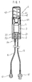
- Fig. 1 is a cross sectionl view showing a self-administration device for liquid drugs of the invention.
- Fig. 2 is a plan view showing the self-administration device for liquid drugs shown in Fig. 1, a liquid drug container connected thereto through flow control means.
- Fig. 3 is an exploded perspective view showing a relation between pushing means and a reservoir in the self-administration device for liquid drugs shown in Fig. 1.
- Fig. 4a-4c is an explanatory view showing a relation between an spring member and mutual engagement means when the pushing means is slid toward the reservoir in the self-administration device for liquid drugs shown in Fig. 1.
- Fig. 5a-5c is an explanatory view showing a relation between the spring member and mutual engagement means in Fig. 4.
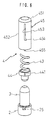
- Fig. 6 is an exploded perspective view showing a relation between pushing means and a reservoir in another embodiment of the self-administration device for liquid drugs of the invention.
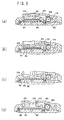
- Fig. 7a-7c is an explanatory view showing a relation between an elastic spring member and the reservoir when the pushing means is slid toward the reservoir in the self-administration device for liquid drugs shown in Fig. 6.
- Fig. 8a-8c is an explanatory view showing a relation between the spring member and mutual engagement means in Fig. 7.
- Fig. 9a-9d is cross sectional view showing the self-administration device for liquid drugs of the prior art.
- a self-administration device for liquid drugs of the invention comprises: a casing 1; a port portion 2: a reservoir 3 closed the open end with the port portion 2, said reservoir being easily deformable by pressing, and restored to its original shape: and pushing means 4 for pressing the reservoir 3, wherein the reservoir 3 is pressed by the pushing means 4 to inject the liquid drug.
- the pushing means 4 includes a cylindrical member inserted slidably into the inner wall of the casing 1, and a spring housed in the cylindrical member for acting as an elastic spring member.
- the cylindrical member and the port portion 2 are respectively provided with a male hook 425 and a female hook 25, for acting as detachable mutual engagement means.
- the reservoir 3 When the cylindrical member of the pushing means 4 is engaged with the port portion 2, the reservoir 3 is pressed by the elastic force of the compressed spring 43. When the shape of the reservoir 3 deformed by the elastic force of the spring 43 is restored to its original shape, the engagement between the cylindrical member and the fort portion 2 can be released.
- the pushing means 4 includes: the cylindrical member composed of two cylinders of an outer case 41 and an inner case 42: the spring 43 housed in the inner case 42 of the cylindrical member coaxially with the inner case 42; and a pushing portion 44 attached to the distal end of the spring 43.
- the pushing means 4 is slidably provided at one open end side of the casing 1 which is usually formed into a cylindrical shape.
- the port portion 2 which has a drug inlet port 21 and a drug outlet port 22 said port portion 2 closing the other open end of the casing 1.
- the reservoir 3 is a container which is easily deformable by pressing and capable of being restored to its original shape for temporarily reserving the liquid drug, said reservoir 3 has a closed end and an open end closed by the port portion 2.
- reference numerals 23 and 24 designate a check valve and a connector, respectively, which are provided at the drug outlet port 22.
- Numeral 5 designates a drug inlet tube
- numeral 6 designates a drug outlet tube.
- the longitudinal slit 423 of the inner case 42 has an oblique portion 424 running oblique direction at the lower end.
- the slits 413 and 423 may have their upper ends aligned, and the lower end of the longitudinal slit 413 of the outer case 41 and the lower end (or the lower end of the oblique portion) of the longitudinal slit 423 of the inner case 42 may be positioned at a level.
- the male hook 425 which is engaged with the female hook 25 at the upper end of the later-described port portion 2.
- the spring 43 is an elastic spring member which is housed and arranged in the inner case 42 coaxially with the pushing means 4, and which provided with the pushing portion 44 at its distal end.
- This pushing portion 44 is arranged adjacent to the closed end of the reservoir 3.
- the side face of the pushing portion 44 has a projection 441.
- the outer case 41 is not turnable in the casing 1, but the inner case 42 is turned backward by the same distance as the transverse component of the oblique portion 414, when the projection 441 moves downward along the oblique portion 424 of the inner case 42 during pressing the spring 43 to the reservoir 3.
- the projection 441 reaches to the lower end portion of the oblique portion 424, the male hook 425 of the inner case 42 and the female hook 25 of the port portion 2 are disengaged with each other.
- the length of the longitudinal slit 11 of the casing 1 is made equal to or slightly larger than the longitudinal slit 413 of the outer case 41.
- the pushing means 4 is so fitted in one open end of the casing 1 that the projection 441 of the pushing portion 44 may be positioned at the upper end of the longitudinal slit 11.
- the other open end of the casing 1 is closed with the port portion 2 which is provided with the drug inlet port 21 and the drug outlet port 22.
- the reservoir 3 is fitted on the port portion 2 inward of the casing 1 or toward the pushing means 4.
- the drug inlet port 21 and the drug outlet port 22 respectively have open end in the reservoir 3, and the drug inlet tube 5 and the drug outlet tube 6 are respectively connected to the drug inlet port 21 and the drug outlet Port 22, as shown in Fig. 2.
- a connector 51 of the drug inlet tube 5 can be connected directly or through flow control means 7 to a liquid drug container 8.
- a connector 61 of the drug outlet tube 6 can be connected to the catheter (not-shown) or the like.
- the drug outlet port 22 is preferably provided with the connector 24 which has the check valve 23 for preventing the back flow of the liquid drug.
- the reservoir 3 temporarily reserves the liquid drug which flows in from the drug inlet port 21.
- This reservoir 3 may be easily deformable by pressing and capable of being restored to its original shape, so said reservoir has a thickness of 1 to 2 mm, for example.
- the reservoir 3 is generally made of the elastic material such as silicone rubber or olefin elastomer or natural rubber.
- the longitudinal slit 11 of the casing 1 may be replaced by a longitudinal groove (not-shown) formed in the inner wall of the casing 1.
- the mutual engagement moans between the inner case 42 and the port portion 2 may be provided the inner case 42 with a female hook (not-shown) to engage with a male hook (not-shown) formed on the port portion 2.
- the mutual engagement means of the port portion 2 may be provided on the inner wall of the casing 1.
- the self-administration device for liquid drugs of the invention may also have a construction shown in Fig. 6.
- pushing means 40 comprises: a cylindrical member 45; a spring 43 housed in the cylindrical member 45, coaxially with said cylindrical member: and a pushing portion 44 attached to the distal end of the spring 43.
- the construction other than the pushing means 40 is similar to that of the self-administration device for liquid drugs shown in Fig. 1.
- the cylindrical member 45 has a top wall 451 and a skirt Portion 452, which has a longitudinal slit 453.
- the longitudinal slit 453 is provided at its lower end with a transversely running portion 454.
- the projection 441 of the pushing portion 44 is movable along the overlapped slits 453 and 11, when the longitudinal slit 453 of the cylindrical member 45 is overlapped with the longitudinal slit 11 (as shown in Fig. 2) formed in the side wall of the casing 1.
- the cylindrical member 45 is not turnable while it is in the longitudinal slit 453.
- the cylindrical member 45 is turnable backward, for the first time, by the same distance as that of the transversely running portion 454, when the projection 441 moves downward along the longitudinal slit 453 and reaches to the lower end of the longitudinally running portion 453 during pressing the spring 43 to the rervoir 3.
- the length of the longitudinal slit 11 of the casing 1 is equal to or slightly larger than the longitudinal slit 453 of the cylindrical member 45.
- the pushing means 40 is fitted in one open end of the casing 1, so that the projection 441 of the pushing portion 44 may be positioned at the upper end of the longitudinal slit 11.
- Fig. 4(a) shows the state when the self-administration device for liquid drugs before pushing the pushing means 4.
- the projection 441 of the inner case 42 is movable along the longitudinal slits 11, 413 and 123 of the casing 1.
- the outer case 41 is restricted to slid upward.
- the spring 43 of the pushing means 4 is slightly pressed by the restoring force of the reservoir 3 and by the pressure of liquid drug coming from the drug inlet port 21.
- the projection 441 of the pushing portion 44 (as indicated by dotted lines)is positioned at the overlapped lower end of the outer case 41 and the inner case 42 (i.e, the lower end of the oblique portion 424).
- the male hook 425 of the inner case 42 is positioned below the upper end of the longitudinal slit 11 of the casing 1 (e.g., below by the distance between the projection 441 and the male hook 425), as shown in Fig. 5(a)
- the flow rate of the liquid drug injected to the human body is controlled by the flow control means 7 in this state.
- the spring 43 is compressed as is shown in Fig. 4(b), so the liquid drug in the reservoir 3 will not abruptly spurt from the drug outlet port 22.
- the male hook 425 of the inner case 42 takes the position, as shown in Fig. 5(b), in which it engages with the female hook 25 (as shown in Fig. 3) of the port portion 2. While the male hook 425 is engaging with the female hook 25, the reservoir 3 is continuously pressed by the spring 43, thus the liquid drug reserved in the reservoir 3 is injected from the drug outlet port 22.
- the projection 441 of the pushing portion 44 moves downward along the longitudinal slit 423 of the inner case 42.
- the inner case 42 While the projection 441 is moving downward in the oblique portion 424 of the longitudinal slit 423, the inner case 42 turns backward by the same distance as the transverse component of the oblique portion 424.
- the male hook 425 of the inner case 42 reaches to the position shown in Fig. 5(c) .
- this male hook 425 is disengaged from the female hook 25 of the port portion 2.
- the spring 43 is pressed by the restoring force of the reservior 3, or at first, by the pressure of the liquid drug injected from the drug inlet port 21, if the restoring force is weak, then the pushing means 4 is slid to the initial position, as shown in Fig. 4(a).
- Fig. 7(a) shows the state of the self-administration device for liquid drugs before the pushing means 4 is pushed.
- the protrution 441 of the pushing portion 44 moving along the longitudinal slit 11 of the casing 1 reaches to the upper end of the longitudinal slit 11, the upward slide of the cylindrical member 45 is restricted to move upward.
- the spring 43 of the pushing means 4 is slightly compressed by the shape retention force of the reservoir 3 and by the pressure of the liquid drug flowing out of the drug inlet port 21.
- the projection 441 of the pushing portion 44 (as indicated by dotted lines) is positioned at the lower end of the overlapping cylindrical member 45.
- a male hook 455 of the cylindrical member 45 is positioned below the upper end of the longitudinal slit 11 of the casing 1, as shown in Fig. 8(a).
- the spring 43 is pressed as is shown in Fig. 7(b), so the liquid drug in the reservoir 3 will not abruptly sport from the drug outlet port 22.
- the male hook 455 of the cylindrical member 45 is positioned as is shown in Fig. 8(b), said male hook 455 engages with the female hook 25 (as shown in Fig. 6) of the port portion 2. While the male hook 455 is engaging with the female hook 25, the reservoir 3 is continuously pressed by the expanding spring 43, then the liquid drug reserved therein are injected from the drug outlet port 22.
- the male hook 455 of the cylindrical member 45 takes the position, as shown in Fig. 8(c).
- the male hook 455 of the cylindrical member 45 can be disengaged from the female hook 25 of the port portion 2.
- the spring 43 is pushed mainly by the restoring force of the reservoir 3, then the pushing moans 4 is slid to the position, as shown in Fig. 7(a).
- the self-administration device for liquid drugs of the invention adopts the spring member as the pushing force for pushing the reservoir.
- the spring member acts as a cushion.
- the reservoir is not pressed more pushing force than necessary, and the reservoir can be pressed by the uniform force, thus the liquid drug will hardly leak. Further, it is free from troubles such as the distal end of the catheter going out of position, when the self-administration device for liquid drugs of the invention is connected to an epidural catheter.
- the pushing means can be fixed in the slid position, so what is required for the patient is to press the pushing means at first, without continuously pressing the pushing means till the liquid drug is completely injected out of the reservoir. Thus making it possible to reduce a charge to the patient.
Landscapes
- Health & Medical Sciences (AREA)
- Vascular Medicine (AREA)
- Engineering & Computer Science (AREA)
- Anesthesiology (AREA)
- Biomedical Technology (AREA)
- Heart & Thoracic Surgery (AREA)
- Hematology (AREA)
- Life Sciences & Earth Sciences (AREA)
- Animal Behavior & Ethology (AREA)
- General Health & Medical Sciences (AREA)
- Public Health (AREA)
- Veterinary Medicine (AREA)
- Infusion, Injection, And Reservoir Apparatuses (AREA)
Abstract
Description
Claims (4)
- A self-administration device for liquid drugs, comprising:a casing having two open ends;a port portion having a drug inlet port and a drug outlet port, the port portion closing the one open ends of the casing;a reservoir having an open end and a closed end, the open end closed by the port portion, wherein the reservoir being easily deformable by pressing and capable of being restored to its original shape ; anda pushing means for pressing the reservior, the pushing means slidably fitted in the other open end of the casing, the reservoir is pressed by the pushing means to inject a liquid drug from the drug outlet port,
wherein the pushing means includes: a cylindrical member inserted slidably into the inner wall of the casing; and an spring member housed in the cylindrical member, wherein mutual engagement means are provided between the cylindrical member and the port portion, when the cylindrical member is slid toward the port portion to bring the cylindrical member and the port portion into engagement with each other, said reservoir is dressed by the elastic force of the compressed spring member. - A self-administration device for liquid drugs according to claim 1, wherein said mutual engagement means is constructed such that when the deformation of the reservoir by the elastic force of the spring member has terminated, the engagement between the cylindrical member and the port portion can be released.
- A self-administration device for liquid drugs according to claim 2, wherein said pushing means includes:an outer case having a top wall and a skirt portion and having a longitudinal slit formed in said skirt portion;an inner case having a top wall and a skirt portion and having a longitudinal slit formed in said skirt portion and having an oblique portion at the lower end and rotatably housed in the outer case, the inner case having male engagement means protruded from the lower end of the skirt portion; anda spring housed in the inner case; anda pushing portion attached to the distal end of the spring,
wherein while the inner case and port portion engaged with each other and then compressed spring expanding, a projection formed on the pushing portion is moved along the longitudinal slit of the outer case and the longitudinal slit of said inner case from the upper end position to the lower end position of the overlapping longitudinal running portions. - A self-administration device for liquid drugs according to claim 2, wherein said pushing means includes:a cylindrical member having a top wall and a skirt portion and having a longitudinal slit formed in said skirt portion and having a transversely running portion at its lower end, said cylindrical member having male engagement portion protruded from the lower end of said skirt portion;a spring housed in said cylindrical member; anda pushing portion attached to the distal end of said spring, and
wherein while the cylindrical member and port portion engaged with each other and compressed spring expanding, a projection formed on said pushing portion is moved along the longitudinal slit of said cylindrical member from the upper end position to the lower end position.
Applications Claiming Priority (3)
| Application Number | Priority Date | Filing Date | Title |
|---|---|---|---|
| JP64879/97 | 1997-03-18 | ||
| JP06487997A JP3208759B2 (en) | 1997-03-18 | 1997-03-18 | Chemical self-injection tool |
| JP6487997 | 1997-03-18 |
Publications (3)
| Publication Number | Publication Date |
|---|---|
| EP0865795A2 true EP0865795A2 (en) | 1998-09-23 |
| EP0865795A3 EP0865795A3 (en) | 1999-06-16 |
| EP0865795B1 EP0865795B1 (en) | 2002-06-12 |
Family
ID=13270857
Family Applications (1)
| Application Number | Title | Priority Date | Filing Date |
|---|---|---|---|
| EP98104801A Expired - Lifetime EP0865795B1 (en) | 1997-03-18 | 1998-03-17 | Self-administration device for liquid drugs |
Country Status (4)
| Country | Link |
|---|---|
| US (1) | US6027491A (en) |
| EP (1) | EP0865795B1 (en) |
| JP (1) | JP3208759B2 (en) |
| DE (1) | DE69805888T2 (en) |
Cited By (1)
| Publication number | Priority date | Publication date | Assignee | Title |
|---|---|---|---|---|
| EP0941741A2 (en) * | 1998-02-27 | 1999-09-15 | Nissho Corporation | Self-administration device for liquid medicines |
Families Citing this family (14)
| Publication number | Priority date | Publication date | Assignee | Title |
|---|---|---|---|---|
| US5976109A (en) * | 1996-04-30 | 1999-11-02 | Medtronic, Inc. | Apparatus for drug infusion implanted within a living body |
| JP3588554B2 (en) * | 1998-10-23 | 2004-11-10 | オーベクス株式会社 | Liquid supply device |
| US6936035B2 (en) * | 2002-12-31 | 2005-08-30 | I-Flow Corporation | Patient controlled drug administration device |
| ATE404233T1 (en) * | 2004-10-21 | 2008-08-15 | Novo Nordisk As | INJECTION DEVICE HAVING MEANS FOR REPORTING THE TIME SINCE THE LAST INJECTION |
| JP4898183B2 (en) * | 2005-10-19 | 2012-03-14 | オーベクス株式会社 | Chemical self-injection system |
| CN101365505A (en) * | 2006-01-06 | 2009-02-11 | 诺沃-诺迪斯克有限公司 | Medication delivery device applying a collapsible reservoir |
| US20100204649A1 (en) * | 2007-04-24 | 2010-08-12 | Vidacare Corporation | High Pressure Intraosseous Bag and Method |
| JP5603335B2 (en) * | 2008-08-29 | 2014-10-08 | ノボ・ノルデイスク・エー/エス | Medical syringe with time delay indicator |
| CA2740875A1 (en) * | 2008-10-15 | 2010-04-22 | Symbios Medical Products, Llc | Electronic flow control |
| JP5517029B2 (en) * | 2009-03-25 | 2014-06-11 | ニプロ株式会社 | Chemical self-injection device |
| CA2760751A1 (en) * | 2009-05-20 | 2010-11-25 | Sanofi-Aventis Deutschland Gmbh | Assembly for use in a drug delivery device |
| US20190388611A1 (en) | 2018-06-20 | 2019-12-26 | Baxter International Inc. | Infusion device |
| WO2020149406A1 (en) * | 2019-01-17 | 2020-07-23 | ニプロ株式会社 | Drug solution injection controller |
| KR102156633B1 (en) * | 2020-05-28 | 2020-09-16 | 이우석 | Medical fluid injector |
Citations (4)
| Publication number | Priority date | Publication date | Assignee | Title |
|---|---|---|---|---|
| WO1987000758A1 (en) * | 1985-08-06 | 1987-02-12 | Baxter Travenol Laboratories, Inc. | Patient-controlled delivery of beneficial agents |
| FR2588757A1 (en) * | 1985-10-21 | 1987-04-24 | Perouse Sa Laboratoires | Device placed under the skin in order to deliver a medicinal substance |
| US4828551A (en) * | 1987-10-13 | 1989-05-09 | Gertler Robert A | Patient controlled analgesia apparatus |
| EP0744182A2 (en) * | 1995-05-24 | 1996-11-27 | Nissho Corporation | Self-administration device for liquid drugs |
Family Cites Families (7)
| Publication number | Priority date | Publication date | Assignee | Title |
|---|---|---|---|---|
| US4312347A (en) * | 1980-02-25 | 1982-01-26 | Iowa State University Research Foundation, Inc. | Positive pressure drug releasing device |
| US4506680A (en) * | 1983-03-17 | 1985-03-26 | Medtronic, Inc. | Drug dispensing body implantable lead |
| US4713054A (en) * | 1986-02-19 | 1987-12-15 | Kelly L Thomas | Implanted muscle powered drug dispensing system |
| US4940460A (en) * | 1987-06-19 | 1990-07-10 | Bioject, Inc. | Patient-fillable and non-invasive hypodermic injection device assembly |
| US5456679A (en) * | 1992-02-18 | 1995-10-10 | Alza Corporation | Delivery devices with pulsatile effect |
| US5697919A (en) * | 1994-04-11 | 1997-12-16 | Tsukada Medical Research Co., Ltd. | Portable analgesic system |
| CA2151407A1 (en) * | 1995-06-09 | 1996-12-10 | Duncan Newman | Injection device |
-
1997
- 1997-03-18 JP JP06487997A patent/JP3208759B2/en not_active Expired - Fee Related
-
1998
- 1998-03-17 DE DE69805888T patent/DE69805888T2/en not_active Expired - Lifetime
- 1998-03-17 EP EP98104801A patent/EP0865795B1/en not_active Expired - Lifetime
- 1998-03-18 US US09/040,291 patent/US6027491A/en not_active Expired - Lifetime
Patent Citations (4)
| Publication number | Priority date | Publication date | Assignee | Title |
|---|---|---|---|---|
| WO1987000758A1 (en) * | 1985-08-06 | 1987-02-12 | Baxter Travenol Laboratories, Inc. | Patient-controlled delivery of beneficial agents |
| FR2588757A1 (en) * | 1985-10-21 | 1987-04-24 | Perouse Sa Laboratoires | Device placed under the skin in order to deliver a medicinal substance |
| US4828551A (en) * | 1987-10-13 | 1989-05-09 | Gertler Robert A | Patient controlled analgesia apparatus |
| EP0744182A2 (en) * | 1995-05-24 | 1996-11-27 | Nissho Corporation | Self-administration device for liquid drugs |
Cited By (3)
| Publication number | Priority date | Publication date | Assignee | Title |
|---|---|---|---|---|
| EP0941741A2 (en) * | 1998-02-27 | 1999-09-15 | Nissho Corporation | Self-administration device for liquid medicines |
| EP0941741A3 (en) * | 1998-02-27 | 2000-04-12 | Nissho Corporation | Self-administration device for liquid medicines |
| US6213981B1 (en) | 1998-02-27 | 2001-04-10 | Nissho Corporation | Self-administration device for liquid medicines |
Also Published As
| Publication number | Publication date |
|---|---|
| EP0865795B1 (en) | 2002-06-12 |
| US6027491A (en) | 2000-02-22 |
| EP0865795A3 (en) | 1999-06-16 |
| JPH10258121A (en) | 1998-09-29 |
| DE69805888T2 (en) | 2002-10-02 |
| JP3208759B2 (en) | 2001-09-17 |
| DE69805888D1 (en) | 2002-07-18 |
Similar Documents
| Publication | Publication Date | Title |
|---|---|---|
| EP0865795B1 (en) | Self-administration device for liquid drugs | |
| JP4156801B2 (en) | Patient controlled drug delivery device | |
| US4544371A (en) | Implantable metered dose drug delivery system | |
| US5061243A (en) | System and apparatus for the patient-controlled delivery of a beneficial agent, and set therefor | |
| US6213981B1 (en) | Self-administration device for liquid medicines | |
| EP0803260B1 (en) | Self-administration device for liquid drugs | |
| JP5539209B2 (en) | Snap-operated disposable infusion device | |
| JP2712907B2 (en) | Apparatus for self-injecting a drug solution and device using the same | |
| JP2010540093A (en) | Disposable infusion device with double valve system | |
| JP6222562B2 (en) | Chemical liquid injection device and chemical liquid injection system including the same | |
| JP5474801B2 (en) | Disposable infusion device that can lock out reuse | |
| JP3147346B2 (en) | Chemical self-injection tool | |
| JP3721777B2 (en) | Chemical solution self-injection set | |
| KR20200032023A (en) | Patient controlled drug administration device | |
| JP7141338B2 (en) | Bolus refill indicator | |
| CN111526901A (en) | Medicine liquid injector with pill counter | |
| CN211214736U (en) | Subcutaneous embedded type drug infusion device for tumor treatment |
Legal Events
| Date | Code | Title | Description |
|---|---|---|---|
| PUAI | Public reference made under article 153(3) epc to a published international application that has entered the european phase |
Free format text: ORIGINAL CODE: 0009012 |
|
| AK | Designated contracting states |
Kind code of ref document: A2 Designated state(s): DE FR GB IT |
|
| AX | Request for extension of the european patent |
Free format text: AL;LT;LV;MK;RO;SI |
|
| PUAL | Search report despatched |
Free format text: ORIGINAL CODE: 0009013 |
|
| AK | Designated contracting states |
Kind code of ref document: A3 Designated state(s): AT BE CH DE DK ES FI FR GB GR IE IT LI LU MC NL PT SE |
|
| AX | Request for extension of the european patent |
Free format text: AL;LT;LV;MK;RO;SI |
|
| 17P | Request for examination filed |
Effective date: 19991129 |
|
| AKX | Designation fees paid |
Free format text: DE FR GB IT |
|
| RAP1 | Party data changed (applicant data changed or rights of an application transferred) |
Owner name: NIPRO CORPORATION |
|
| GRAG | Despatch of communication of intention to grant |
Free format text: ORIGINAL CODE: EPIDOS AGRA |
|
| GRAG | Despatch of communication of intention to grant |
Free format text: ORIGINAL CODE: EPIDOS AGRA |
|
| GRAH | Despatch of communication of intention to grant a patent |
Free format text: ORIGINAL CODE: EPIDOS IGRA |
|
| 17Q | First examination report despatched |
Effective date: 20011105 |
|
| GRAH | Despatch of communication of intention to grant a patent |
Free format text: ORIGINAL CODE: EPIDOS IGRA |
|
| GRAA | (expected) grant |
Free format text: ORIGINAL CODE: 0009210 |
|
| AK | Designated contracting states |
Kind code of ref document: B1 Designated state(s): DE FR GB IT |
|
| REG | Reference to a national code |
Ref country code: GB Ref legal event code: FG4D |
|
| REF | Corresponds to: |
Ref document number: 69805888 Country of ref document: DE Date of ref document: 20020718 |
|
| ET | Fr: translation filed | ||
| PLBE | No opposition filed within time limit |
Free format text: ORIGINAL CODE: 0009261 |
|
| STAA | Information on the status of an ep patent application or granted ep patent |
Free format text: STATUS: NO OPPOSITION FILED WITHIN TIME LIMIT |
|
| 26N | No opposition filed |
Effective date: 20030313 |
|
| PGFP | Annual fee paid to national office [announced via postgrant information from national office to epo] |
Ref country code: IT Payment date: 20120320 Year of fee payment: 15 |
|
| PGFP | Annual fee paid to national office [announced via postgrant information from national office to epo] |
Ref country code: DE Payment date: 20130314 Year of fee payment: 16 Ref country code: GB Payment date: 20130313 Year of fee payment: 16 Ref country code: FR Payment date: 20130325 Year of fee payment: 16 |
|
| REG | Reference to a national code |
Ref country code: DE Ref legal event code: R119 Ref document number: 69805888 Country of ref document: DE |
|
| GBPC | Gb: european patent ceased through non-payment of renewal fee |
Effective date: 20140317 |
|
| REG | Reference to a national code |
Ref country code: FR Ref legal event code: ST Effective date: 20141128 |
|
| REG | Reference to a national code |
Ref country code: DE Ref legal event code: R119 Ref document number: 69805888 Country of ref document: DE Effective date: 20141001 |
|
| PG25 | Lapsed in a contracting state [announced via postgrant information from national office to epo] |
Ref country code: DE Free format text: LAPSE BECAUSE OF NON-PAYMENT OF DUE FEES Effective date: 20141001 Ref country code: GB Free format text: LAPSE BECAUSE OF NON-PAYMENT OF DUE FEES Effective date: 20140317 Ref country code: FR Free format text: LAPSE BECAUSE OF NON-PAYMENT OF DUE FEES Effective date: 20140331 |
|
| PG25 | Lapsed in a contracting state [announced via postgrant information from national office to epo] |
Ref country code: IT Free format text: LAPSE BECAUSE OF NON-PAYMENT OF DUE FEES Effective date: 20140317 |