EP0865210A2 - Improvements in or relating to display systems - Google Patents
Improvements in or relating to display systems Download PDFInfo
- Publication number
- EP0865210A2 EP0865210A2 EP98200445A EP98200445A EP0865210A2 EP 0865210 A2 EP0865210 A2 EP 0865210A2 EP 98200445 A EP98200445 A EP 98200445A EP 98200445 A EP98200445 A EP 98200445A EP 0865210 A2 EP0865210 A2 EP 0865210A2
- Authority
- EP
- European Patent Office
- Prior art keywords
- lamp
- color
- light
- light source
- driven
- Prior art date
- Legal status (The legal status is an assumption and is not a legal conclusion. Google has not performed a legal analysis and makes no representation as to the accuracy of the status listed.)
- Granted
Links
Images


Classifications
-
- H—ELECTRICITY
- H04—ELECTRIC COMMUNICATION TECHNIQUE
- H04N—PICTORIAL COMMUNICATION, e.g. TELEVISION
- H04N9/00—Details of colour television systems
- H04N9/12—Picture reproducers
- H04N9/31—Projection devices for colour picture display, e.g. using electronic spatial light modulators [ESLM]
- H04N9/3102—Projection devices for colour picture display, e.g. using electronic spatial light modulators [ESLM] using two-dimensional electronic spatial light modulators
- H04N9/3111—Projection devices for colour picture display, e.g. using electronic spatial light modulators [ESLM] using two-dimensional electronic spatial light modulators for displaying the colours sequentially, e.g. by using sequentially activated light sources
- H04N9/3114—Projection devices for colour picture display, e.g. using electronic spatial light modulators [ESLM] using two-dimensional electronic spatial light modulators for displaying the colours sequentially, e.g. by using sequentially activated light sources by using a sequential colour filter producing one colour at a time
-
- H—ELECTRICITY
- H04—ELECTRIC COMMUNICATION TECHNIQUE
- H04N—PICTORIAL COMMUNICATION, e.g. TELEVISION
- H04N9/00—Details of colour television systems
- H04N9/12—Picture reproducers
- H04N9/31—Projection devices for colour picture display, e.g. using electronic spatial light modulators [ESLM]
- H04N9/3141—Constructional details thereof
- H04N9/315—Modulator illumination systems
- H04N9/3155—Modulator illumination systems for controlling the light source
-
- H—ELECTRICITY
- H04—ELECTRIC COMMUNICATION TECHNIQUE
- H04N—PICTORIAL COMMUNICATION, e.g. TELEVISION
- H04N9/00—Details of colour television systems
- H04N9/12—Picture reproducers
- H04N9/31—Projection devices for colour picture display, e.g. using electronic spatial light modulators [ESLM]
- H04N9/3141—Constructional details thereof
- H04N9/315—Modulator illumination systems
- H04N9/3164—Modulator illumination systems using multiple light sources
-
- H—ELECTRICITY
- H04—ELECTRIC COMMUNICATION TECHNIQUE
- H04N—PICTORIAL COMMUNICATION, e.g. TELEVISION
- H04N5/00—Details of television systems
- H04N5/74—Projection arrangements for image reproduction, e.g. using eidophor
- H04N5/7416—Projection arrangements for image reproduction, e.g. using eidophor involving the use of a spatial light modulator, e.g. a light valve, controlled by a video signal
- H04N5/7441—Projection arrangements for image reproduction, e.g. using eidophor involving the use of a spatial light modulator, e.g. a light valve, controlled by a video signal the modulator being an array of liquid crystal cells
-
- H—ELECTRICITY
- H04—ELECTRIC COMMUNICATION TECHNIQUE
- H04N—PICTORIAL COMMUNICATION, e.g. TELEVISION
- H04N5/00—Details of television systems
- H04N5/74—Projection arrangements for image reproduction, e.g. using eidophor
- H04N5/7416—Projection arrangements for image reproduction, e.g. using eidophor involving the use of a spatial light modulator, e.g. a light valve, controlled by a video signal
- H04N5/7458—Projection arrangements for image reproduction, e.g. using eidophor involving the use of a spatial light modulator, e.g. a light valve, controlled by a video signal the modulator being an array of deformable mirrors, e.g. digital micromirror device [DMD]
Definitions
- the present invention generally relates to projection display systems, and more particularly to a display system having a single light valve and multiple lamps achieving improved color balance and brightness.
- SLMs spatial Light Modulators
- light valves are devices that modulate incident light in a spatial pattern corresponding to an electrical or optical input.
- the incident light may be modulated in its phase, intensity, polarization, or direction.
- the light image is directed and focused to a screen in the case of a projector, video monitor or display, or is ultimately focused on a light sensitive material, such as a photoreceptor drum, in the case of a xerographic printer.
- the light modulation may be achieved by a variety of materials exhibiting various electro-optic or magneto-optic effects, and by materials that modulate light by surface deformation.
- Other spatial light modulators may include tiny micro-mechanical devices comprising an array of positionable picture elements (pixels).
- the light image can be colored if it is to be displayed on a screen of a projector, monitor, or a television and the like. This coloring is typically done in one of two ways, either using non-sequential color systems, or using sequential color systems.
- a non-sequential color system simultaneously images multiple colours of light, such as red, green and blue light.
- An example of a non-sequential color system is discussed in commonly assigned U.S. Patent 5,452,024 to Sampsell, entitled "DMD Display System”.
- sequential color systems color images are generated by sequentially projecting imaged coloured light, (i.e. red, green and blue light), in a single image frame, which typically lasts 1/60 of a second.
- Sequential color systems typically utilize a color wheel that is partitioned into a plurality of color of segments (such as a red, green and blue segment) or multiples/combinations thereof.
- An example of a sequential color system is disclosed in commonly assigned U.S. Patent 5,448,314 to Heimbuch, et al entitled "Method and Apparatus for Sequential Colour Imaging".
- DMD digital micromirror device
- the DMD is a spatial light modulator suitable for use in displays, projectors and hard copy printers.
- the DMD is a monolithic single-chip integrated circuit, comprising a high density array of, for example, 17 micron square deflectable micromirrors. These mirrors are fabricated over address circuitry including an array of SRAM cells and address electrodes. Each mirror forms one pixel of the DMD array and is bi-stable, that is to say, stable in one of two positions.
- a source of light directed upon the mirror array will be reflected in one of two directions by each mirror.
- incident light to that mirror will be reflected to a collector lens and focused onto a display screen or a photosensitive element of a printer, and forms an image of the mirror/pixel.
- the other "OFF" mirror position light directed onto the mirror will be deflected to a light absorber.
- Each mirror of the array is individually controlled to either direct incident light into the collector lens, or to the light absorber.
- a projector lens and a light prism ultimately focus and magnify the modulated image from the pixel mirrors onto a display screen and produce a viewable image. If each pixel mirror of the DMD array is in the "ON" position, the displayed image will be an array of bright pixels.
- Gray scale of the pixels forming the image can be achieved by pulse width modulation techniques of the mirrors, such as that described in U.S.Patent 5,278,652 entitled “DMD Architecture and Timing for Use in a Pulse-Width Modulated Display System", assigned to the same assignee of the present invention.
- non-sequential color systems three (3) DMD arrays can be used to form an image plane, one DMD for modulating red, green and blue light, as disclosed in the commonly assigned U.S. Patent 5,452,024 to Sampsell, titled "DMD Display System".
- a sequential color system requires only one such DMD device, with the red, green, and blue light being sequentially modulated and reflected by the single DMD array onto an image plane.
- the non-sequential colour system needs three DMD arrays, and attendant hardware when compared with the sequential color system, but offers increased display brightness.
- the lamp may typically be comprised of a xenon or metal halide arc lamp, or a laser. This arc lamp may be powered by an AC or DC power source.
- Multiple light sources can also be implemented in a sequential color system Using a single light valve, as disclosed in U.S. Patent 5,428,408.
- This system includes three projection lamps, one for each of the primary colors, which are sequentially activated. Three occluders are utilized, one blocking or unblocking the light output from the associated lamp. The light output from the associated lamp that ultimately illuminates the light valve is controlled by the pulse driven occluders.
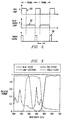
- Conventional arc lamps which may consist of xenon or metal halide arc lamps, are typically deficient in intensity in some portion of the color spectrum. That is, for a given power input, the associated light output levels of red, blue, and green light are unbalanced. A typical lamp is most deficient in red light, and most sufficient in green light.
- One solution is to address color balance disclosed in the commonly assigned U.S. Patent application Serial No. 08/414,707 entitled "Spatial Light Image Display System with Synchronized and Modulated Light Source", where each of three lights can be individually driven and amplitude modulated to achieve color balance.
- the present invention achieves technical advantages as a two lamp single light valve imaging system.
- One lamp is utilized for generating red light
- a second lamp is utilized for generating both blue and green light.
- the first lamp is driven at 3X it rated power rating for 1/3 of a video frame, thus being driven at its average power rating over 1 video frame.
- the second lamp is pulse driven at 150% of its rated power rating for 2/3 of a video frame, thus also being driven at its average power rating over 1 video frame.
- the display system of a preferred embodiment of the present invention comprises a light valve for modulating a light beam impinging thereon as a function of an incoming video signal representing a series of video frames.
- First and second lamps generate a first light source and a second light source, respectively. Optics direct the first light source and the second light source to the light valve to form the light beam.
- a light coloring device colors the first light source a first color, and also alternately colors the second light source a second color and a third color.
- a lamp driver circuit pulse drives the first lamp when the color device colors the first light source the first color, the lamp driver circuit also pulse drives the second lamp when the color device alternately colors the second light source the second color and the third color.
- the first and second lamps are pulse driven at a peak power level higher than average power rating of the respective lamp, but the lamps operate at a rated power level over each video frame to last an acceptable life span.
- pulse driving these lamps above their power ratings achieves greater light output for the respective color, thereby achieving a brighter image as formed by the light valve.
- the first color is preferably red which is the most deficient color, and the second and third colors being blue and green, respectively.
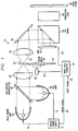
- Imaging system 10 is seen to include a pulse driven lamp controller and power supply 12 having two pulsed drive outputs 14 and 16.
- the lamp controller and power supply 12 provides lamp drive signals on outputs 14 and 16 as a function of a timing signal provided on input line 18.
- a video data formatter 20 provides the timing signal on line 18, which timing signal is synchronized to a wheel position signal provided, or received in the alternative, by video data formatter 20 on outline 22.
- the timing signal provided on line 18 is syncrhonized with the position of the colored segments 24 of a color wheel 26, having for example red, green and blue color segments.
- a signal such as the leading edge of a pulse or other equivalent signal, is generated by video data formatter as the red color segment 24 is positioned to color the incident generated light.
- Video data formatter 20 controls a DC stepper motor 30 to precisely rotate color wheel 26 at 60 rotations per second, which corresponds to the 60 frames per second of video data provided on input line 32.
- an optical sensor can be provided if desired to sense a marker on the wheel 26 proximate the red segment to further ascertain when the red segment 24 is being illuminated.
- a first projection arc lamp 40 is seen to be pulse driven by the pulsed drive output 14 provided by the pulsed power supply 12.
- the first lamp 40 is used to ultimately generate red light. More specifically, lamp 40 generates white light towards a dichroic filter or beam splitter 46. This beam splitter reflects the red component of the incident light towards a first condenser lens 48, and passes the blue and green components of the white light. Lamp 40 is pulse driven only when the red segment 24 of color wheel 26 is being illuminated.
- a second projection arc lamp 50 is provided for ultimately generating blue and green light.
- Lamp 50 is pulse driven by the pulsed drive output 16.
- Lamp 50 generates and directs white light to beam splitter 46, whereby the green and blue components of the incident light is transmitted therethrough, with the red component of the light being reflected away from lens 48.
- Lamp 50 is driven by pulsed power supply 12 and generates light only when the blue and green segments 24 of color wheel 26 are advanced to color the incident light focused thereon by optics lens 48.
- the multiple color segments 24 provided on wheel 26 are typically red, blue and green. In some applications, two color segments of each color are provided, for a total of six color segments. In yet another alternative application, color segments of different colors can be utilized, such as clear, yellow and blue or yellow, yellow and blue if desired. The advantage of using these colored segments for a color wheel is that the coatings are easier to manufacture and therefore are cheaper.
- the red lamp 40 is pulsed on by power supply 12 either a clear segment or a yellow segment of the color wheel 25 is used to transmit red light.
- the blue-green lamp 50 is pulsed on by power supply 12, the blue segment of the color wheel 26 is used to transmit red light.
- the blue segment of the color wheel 26 is used to transmit blue light and the yellow segment to transmit green light.
- the red-green-blue color can be replaced by a clear-yellow-blue, or a yellow-yellow-blue color wheel. If three color segments are provided, each segment is illuminated 1/180 th of a second, or once each video frame. If six colored segments are utlized, each segment is illuminated 1,360th of a second, again, each color segment being illuminated one time each video frame.
- the colored light 52 generated by color wheel 26 is seen to be transmitted to a second condenser lens 54 and focused upon a light reflector 56.
- the colored light 52 is preferably directed by reflector 56 to a total internal reflection (TIR) prism 60.
- Prism 60 reflects the colored light to a light valve 62, such as a DMD, an LCD or other suitable light valve, for imaging. It is noted that use of reflector 56 and prism 60 is not necessary, but is desired to achieve compactness of the system.
- the light valve 62 separately images the sequence of colored light according to a video data signal on line 64 is color frame data coordinated with the position of the color wheel 26.
- the video data signal on line 64 corresponds to the color of light being modulated by valve 62.
- This imaged light is reflected back to the TIR prism 60, prism 60 directing the imaged light to a projection lens 66 and ultimately focusing light at an image plane, such as a display screen 68.
- the eye fuses the three sequential color subfields generated by valve 62 into full motion, full color video.
- the first or red lamp 40 is driven by a pulsed drive signal seen as waveforms 80.
- the second lamp 50 or blue-green lamp, is driven by a pulsed signal seen as waveform 82.
- Waveform 80 and 82 are each timed from the timing signal 86 generated on line 18.
- the red lamp is driven such that the peak power level of waveform 80 is 3X the average peak power rating of the associated lamp 40 for 1/3 of a video frame, i.e. 1/180th of a second. Thus, for one video frame the lamp 40 is driven at its average power rating.
- the blue-green lamp 50 is pulse driven by waveform 82 at a peak power level that is 150% of the average power rating of the associated arc lamp, 50 for 2/3 of a video frame, i.e. 1/90th of a second.
- the second lamp 50 is also driven at its average power rating for one video frame.
- the associated lamps provide a significantly increased lamp output that is higher than the average power rating of the lamp, providing increased brightness of light ultimately imaged by the light valve 62 and visually observed at image plane 68. That is, imaged red light is generated to be 3X the brightness of that obtainable if only a single lamp was utilized and driven 100% of the time at its average power rating.
- a 150% increase of the imaged blue light and green light is achieved by driving the second lamp at a peak power, that is 50% higher than its average rating for 2/3 of a video frame. Since the two lamps, which are preferably identical, are typical deficient in the red spectrum, the brightness of the red light now available for imaging is 3X brighter while only using two lamps.
- Each of the projection lamps 40 and 50 is preferably driven at a consistent power level (i.e. their rated power level) and will thus have a sufficient life span.
- the illustrated embodiments provide improved image brightness and color balance as compared to a single light source system, and utilizes a single light valve.
- the architecture is simple and less costly than a system utilizing three light sources.
- the disclosed embodiments of the invention are intended to include a two lamp illumination system synchronized with a color filter and a single light valve for improved color balance and brightness.
Landscapes
- Engineering & Computer Science (AREA)
- Multimedia (AREA)
- Signal Processing (AREA)
- Video Image Reproduction Devices For Color Tv Systems (AREA)
- Projection Apparatus (AREA)
Abstract
Description
Claims (9)
- A display system, comprising:a light valve for modulating a light beam impinging thereon as a function of a video signal representing a series of video frames;a first lamp and a second lamp for generating a first light source and a second light source, respectively;optics for directing said first light source and said second light source to said light valve to form said light beam;color means for coloring said first light source a first color and for alternately coloring said second light source a second color and a third color; anda lamp driver circuit for driving said first lamp when said color means colors said first light source said first color, for driving said second lamp when said color means alternately colors said second light source said second color and said third color.
- The display system as claimed in Claim 1, wherein said first lamp and said second lamp are pulse driven by a lamp driver circuit at a peak power level higher than an average power rating of the respective lamp.
- The display system as claimed in Claim 1 or Claim 2, wherein said first color is red, and said second color and said third color are blue and green, respectively.
- The display system as claimed in any preceding Claim, wherein said first lamp is driven for approximately one-third the time for each said video frame, and said second lamp is driven for approximately two-thirds the time for each said video frame.
- The display system as claimed in any preceding Claim, wherein said first lamp is driven at a peak power level approximately three times the average power rating of said first lamp.
- The display system as claimed in any preceding Claim, wherein said second lamp is driven at a peak power level approximately one and one-half the average power rating of said second lamp.
- The display system as claimed in any preceding Claim, wherein said first lamp and said second lamp comprise an arc lamp.
- A method of operating a display system as a function of a video signal representing a series of video frames, comprising the steps of:driving a first lamp a first fraction of each said video frame to generate a first light source, and driving a second lamp a second fraction of each said video frame to generate a second light source;coloring said first light source a first color, and alternately coloring said second light source a second color and a third color;directing said colored first light source and said colored second light source to a light valve; andmodulating said colored first light source and said second light source with said light valve to form an image.
- The method as claimed in Claim 8, further comprising the step of;pulse driving said first light source and said second light source at a peak power higher than an average power rating of the respective lamp.
Applications Claiming Priority (2)
| Application Number | Priority Date | Filing Date | Title |
|---|---|---|---|
| US4053397P | 1997-03-12 | 1997-03-12 | |
| US40533P | 1997-03-12 |
Publications (3)
| Publication Number | Publication Date |
|---|---|
| EP0865210A2 true EP0865210A2 (en) | 1998-09-16 |
| EP0865210A3 EP0865210A3 (en) | 2001-01-17 |
| EP0865210B1 EP0865210B1 (en) | 2006-07-26 |
Family
ID=21911503
Family Applications (1)
| Application Number | Title | Priority Date | Filing Date |
|---|---|---|---|
| EP98200445A Expired - Lifetime EP0865210B1 (en) | 1997-03-12 | 1998-02-12 | Colour-sequential video display system |
Country Status (3)
| Country | Link |
|---|---|
| US (1) | US6252636B1 (en) |
| EP (1) | EP0865210B1 (en) |
| DE (1) | DE69835311T2 (en) |
Cited By (5)
| Publication number | Priority date | Publication date | Assignee | Title |
|---|---|---|---|---|
| US6586892B2 (en) | 2000-05-03 | 2003-07-01 | Koninklijke Philips Electronics N.V. | Method of and device for operating a gas discharge lamp |
| US6631996B2 (en) | 2000-05-12 | 2003-10-14 | Koninklijke Philips Electronics N.V. | Projection system, and method of operating a projection system |
| WO2004032523A1 (en) * | 2002-10-01 | 2004-04-15 | Koninklijke Philips Electronics N.V. | Color display device |
| CN100396105C (en) * | 2002-08-13 | 2008-06-18 | 汤姆森许可贸易公司 | Method of operating a pulse width modulated display system with hybrid coding |
| CN110650324A (en) * | 2018-06-27 | 2020-01-03 | 深圳光峰科技股份有限公司 | Projection equipment, projection system and projection method |
Families Citing this family (61)
| Publication number | Priority date | Publication date | Assignee | Title |
|---|---|---|---|---|
| WO1999056166A2 (en) * | 1998-04-28 | 1999-11-04 | Carl Zeiss Jena Gmbh | Projection device |
| WO2000065399A2 (en) * | 1999-04-23 | 2000-11-02 | Koninklijke Philips Electronics N.V. | Projection system |
| US6377236B1 (en) * | 1999-07-29 | 2002-04-23 | Hewlett-Packard Company | Method of illuminating a light valve with improved light throughput and color balance correction |
| US6623122B1 (en) * | 1999-09-30 | 2003-09-23 | Semiconductor Energy Laboratory Co., Ltd. | Light source optical system and projector having first and second lamps of different spectral distributions |
| JP2001142144A (en) * | 1999-11-11 | 2001-05-25 | Minolta Co Ltd | Illuminating system and projector |
| US8487850B1 (en) | 2000-06-05 | 2013-07-16 | Hewlett-Packard Development Company, L.P. | Multi-source LCD backlight for white balance adjustment |
| US6733139B2 (en) * | 2000-06-05 | 2004-05-11 | Hewlett-Packard Development Company, L.P. | Projector with narrow-spectrum light source to complement broad-spectrum light source |
| KR100370658B1 (en) * | 2000-12-22 | 2003-02-05 | 삼성전기주식회사 | Device for color separation and combination |
| US6520648B2 (en) | 2001-02-06 | 2003-02-18 | Infocus Corporation | Lamp power pulse modulation in color sequential projection displays |
| US6859239B2 (en) * | 2001-02-26 | 2005-02-22 | Infocus Corporation | Projection system with folded optical path |
| US20050105061A1 (en) * | 2001-03-15 | 2005-05-19 | Delong James A. | Projection system with folded optical path |
| JP2002287084A (en) * | 2001-03-28 | 2002-10-03 | Fuji Photo Optical Co Ltd | Projection type image display device using reflection type liquid crystal display element |
| US6690432B2 (en) * | 2001-04-12 | 2004-02-10 | Koninklijke Philips Electronics N.V. | Alignment of the optical and the electrical scan in a scrolling color projector |
| KR20060035810A (en) * | 2002-02-26 | 2006-04-26 | 유니-픽셀 디스플레이스, 인코포레이티드 | Air gap naturally occurring mechanism |
| JP2003255465A (en) * | 2002-02-28 | 2003-09-10 | Toshiba Corp | Illumination device and projection display device using the same |
| JP4055610B2 (en) * | 2002-03-22 | 2008-03-05 | セイコーエプソン株式会社 | Image display device and projector |
| TWI235263B (en) * | 2002-05-14 | 2005-07-01 | Sony Corp | Illuminating optical system, image display unit and method of illuminating space modulation element |
| US7064795B2 (en) * | 2002-09-19 | 2006-06-20 | Koninklijke Philips Electronics N.V. | Temporal dithering to increase dynamic range of images in sequentially illuminated displays |
| US6896381B2 (en) * | 2002-10-11 | 2005-05-24 | Light Prescriptions Innovators, Llc | Compact folded-optics illumination lens |
| US7377671B2 (en) * | 2003-02-04 | 2008-05-27 | Light Prescriptions Innovators, Llc | Etendue-squeezing illumination optics |
| US7329029B2 (en) * | 2003-05-13 | 2008-02-12 | Light Prescriptions Innovators, Llc | Optical device for LED-based lamp |
| US8075147B2 (en) * | 2003-05-13 | 2011-12-13 | Light Prescriptions Innovators, Llc | Optical device for LED-based lamp |
| EP1664851B1 (en) * | 2003-07-28 | 2014-11-12 | Light Prescriptions Innovators, LLC. | Three-dimensional simultaneous multiple-surface method and free-form illumination-optics designed therefrom |
| US7070301B2 (en) | 2003-11-04 | 2006-07-04 | 3M Innovative Properties Company | Side reflector for illumination using light emitting diode |
| US7144121B2 (en) * | 2003-11-14 | 2006-12-05 | Light Prescriptions Innovators, Llc | Dichroic beam combiner utilizing blue LED with green phosphor |
| US7090357B2 (en) * | 2003-12-23 | 2006-08-15 | 3M Innovative Properties Company | Combined light source for projection display |
| JP2005196011A (en) * | 2004-01-09 | 2005-07-21 | Ushio Inc | Light source device for projector device |
| US7101063B2 (en) * | 2004-02-05 | 2006-09-05 | Hewlett-Packard Development Company, L.P. | Systems and methods for integrating light |
| US7427146B2 (en) * | 2004-02-11 | 2008-09-23 | 3M Innovative Properties Company | Light-collecting illumination system |
| US7300177B2 (en) * | 2004-02-11 | 2007-11-27 | 3M Innovative Properties | Illumination system having a plurality of light source modules disposed in an array with a non-radially symmetrical aperture |
| US7246923B2 (en) * | 2004-02-11 | 2007-07-24 | 3M Innovative Properties Company | Reshaping light source modules and illumination systems using the same |
| JP2005309134A (en) * | 2004-04-22 | 2005-11-04 | Hitachi Ltd | Image display device and light source unit thereof |
| US7101050B2 (en) | 2004-05-14 | 2006-09-05 | 3M Innovative Properties Company | Illumination system with non-radially symmetrical aperture |
| EP1767001B1 (en) * | 2004-07-02 | 2009-04-15 | Koninklijke Philips Electronics N.V. | Color display |
| US7244031B2 (en) * | 2004-07-08 | 2007-07-17 | Hewlett-Packard Development Company, L.P. | Light source arrangement |
| US7390097B2 (en) | 2004-08-23 | 2008-06-24 | 3M Innovative Properties Company | Multiple channel illumination system |
| TWI263800B (en) * | 2005-02-01 | 2006-10-11 | Coretronic Corp | Optical projection apparatus |
| KR20070116980A (en) * | 2005-04-04 | 2007-12-11 | 코닌클리케 필립스 일렉트로닉스 엔.브이. | Color conversion unit for reduced fringing |
| WO2007014371A2 (en) * | 2005-07-28 | 2007-02-01 | Light Prescriptions Innovators, Llc | Etendue-conserving illumination-optics for backlights and frontlights |
| US8419232B2 (en) * | 2005-07-28 | 2013-04-16 | Light Prescriptions Innovators, Llc | Free-form lenticular optical elements and their application to condensers and headlamps |
| KR100772398B1 (en) * | 2006-02-25 | 2007-11-01 | 삼성전자주식회사 | 2. Scanning light source, imaging device using same and driving method thereof |
| DE102006009975A1 (en) * | 2006-03-03 | 2007-09-06 | Patent-Treuhand-Gesellschaft für elektrische Glühlampen mbH | Lighting device and display system with a lighting device |
| TWI307782B (en) * | 2006-05-16 | 2009-03-21 | Delta Electronics Inc | Projector apparatus with multi-light sources and light coupling module thereof |
| WO2008008994A2 (en) * | 2006-07-14 | 2008-01-17 | Light Prescriptions Innovators, Llc | Brightness-enhancing film |
| WO2008022064A2 (en) * | 2006-08-10 | 2008-02-21 | Light Prescriptions Innovators, Llc | Led light recycling device |
| WO2008022065A2 (en) * | 2006-08-11 | 2008-02-21 | Light Prescriptions Innovators, Llc | Led luminance-enhancement and color-mixing by rotationally multiplexed beam-combining |
| CN102016402A (en) * | 2008-02-21 | 2011-04-13 | 光处方革新有限公司 | Spherically emitting remote phosphor |
| DE102008059639A1 (en) | 2008-11-28 | 2010-06-02 | Osram Gesellschaft mit beschränkter Haftung | Method and device for color balance of a light unit |
| WO2010146683A1 (en) * | 2009-06-18 | 2010-12-23 | Necディスプレイソリューションズ株式会社 | Optical unit and projection display device |
| JP4742349B2 (en) * | 2009-06-30 | 2011-08-10 | カシオ計算機株式会社 | Light source device and projector |
| JP4924677B2 (en) * | 2009-08-21 | 2012-04-25 | カシオ計算機株式会社 | Light source device, projection device, and projection method |
| JP2011128494A (en) * | 2009-12-21 | 2011-06-30 | Sanyo Electric Co Ltd | Projection video display device |
| JP4973962B2 (en) * | 2010-03-31 | 2012-07-11 | カシオ計算機株式会社 | Light source device and projector |
| JP5223941B2 (en) * | 2011-03-28 | 2013-06-26 | カシオ計算機株式会社 | Projection device |
| US8646947B2 (en) * | 2011-06-29 | 2014-02-11 | Appotronics Corporation Limited | Multicolor illumination device using multiple light sources and a moving plate with wavelength conversion materials |
| US8740406B2 (en) * | 2011-08-25 | 2014-06-03 | Appotronics Corporation Limited | Method and apparatus for solid state illumination |
| US8616705B2 (en) * | 2011-11-04 | 2013-12-31 | Appotronics (China) Corporation | Light source device and projection display method |
| CN102854733B (en) * | 2012-08-06 | 2015-06-24 | 深圳市绎立锐光科技开发有限公司 | Lighting device and related projection system |
| JP6205835B2 (en) * | 2013-05-14 | 2017-10-04 | 株式会社リコー | LIGHTING DEVICE, PROJECTION DEVICE PROVIDED WITH THIS LIGHTING DEVICE, AND LIGHTING METHOD |
| JP6512435B2 (en) * | 2015-04-10 | 2019-05-15 | パナソニックIpマネジメント株式会社 | projector |
| US11652963B2 (en) * | 2017-11-14 | 2023-05-16 | Signify Holding B.V. | Solid state light sources enabling spokes when used with a color wheel |
Family Cites Families (6)
| Publication number | Priority date | Publication date | Assignee | Title |
|---|---|---|---|---|
| US4546379A (en) * | 1983-04-21 | 1985-10-08 | Welch Allyn, Inc. | Independent color adjustment for a video system |
| JP3015201B2 (en) * | 1992-05-06 | 2000-03-06 | キヤノン株式会社 | Image forming apparatus, projection display apparatus, and light modulation apparatus |
| US5386250A (en) * | 1993-08-09 | 1995-01-31 | Philips Electronics North America Corp. | Two-source illumination system |
| US5428408A (en) * | 1994-05-26 | 1995-06-27 | Philips Electronics North America Corporation | Color correction system for projection video system utilizing multiple light sources |
| US5668611A (en) * | 1994-12-21 | 1997-09-16 | Hughes Electronics | Full color sequential image projection system incorporating pulse rate modulated illumination |
| US5680180A (en) * | 1995-05-08 | 1997-10-21 | Texas Instruments Incorporated | Color balance compensation for digital display system with color wheel |
-
1998
- 1998-02-12 EP EP98200445A patent/EP0865210B1/en not_active Expired - Lifetime
- 1998-02-12 DE DE69835311T patent/DE69835311T2/en not_active Expired - Lifetime
- 1998-03-11 US US09/038,346 patent/US6252636B1/en not_active Expired - Lifetime
Cited By (11)
| Publication number | Priority date | Publication date | Assignee | Title |
|---|---|---|---|---|
| US6586892B2 (en) | 2000-05-03 | 2003-07-01 | Koninklijke Philips Electronics N.V. | Method of and device for operating a gas discharge lamp |
| CN1336783B (en) * | 2000-05-03 | 2010-12-01 | 皇家菲利浦电子有限公司 | Method and arrangement for operating gas discharge lamp |
| US6631996B2 (en) | 2000-05-12 | 2003-10-14 | Koninklijke Philips Electronics N.V. | Projection system, and method of operating a projection system |
| CN100396105C (en) * | 2002-08-13 | 2008-06-18 | 汤姆森许可贸易公司 | Method of operating a pulse width modulated display system with hybrid coding |
| WO2004032523A1 (en) * | 2002-10-01 | 2004-04-15 | Koninklijke Philips Electronics N.V. | Color display device |
| JP2006501513A (en) * | 2002-10-01 | 2006-01-12 | コーニンクレッカ フィリップス エレクトロニクス エヌ ヴィ | Color display device |
| US7430022B2 (en) | 2002-10-01 | 2008-09-30 | Koninklijke Philips Electronics N.V. | Color display device |
| CN1685738B (en) * | 2002-10-01 | 2010-11-03 | 皇家飞利浦电子股份有限公司 | color display device |
| JP4808967B2 (en) * | 2002-10-01 | 2011-11-02 | コーニンクレッカ フィリップス エレクトロニクス エヌ ヴィ | Color display device and operating method thereof |
| CN110650324A (en) * | 2018-06-27 | 2020-01-03 | 深圳光峰科技股份有限公司 | Projection equipment, projection system and projection method |
| CN110650324B (en) * | 2018-06-27 | 2022-03-29 | 深圳光峰科技股份有限公司 | Projection equipment, projection system and projection method |
Also Published As
| Publication number | Publication date |
|---|---|
| EP0865210B1 (en) | 2006-07-26 |
| EP0865210A3 (en) | 2001-01-17 |
| DE69835311T2 (en) | 2007-07-19 |
| US6252636B1 (en) | 2001-06-26 |
| DE69835311D1 (en) | 2006-09-07 |
Similar Documents
| Publication | Publication Date | Title |
|---|---|---|
| EP0865210B1 (en) | Colour-sequential video display system | |
| US5706061A (en) | Spatial light image display system with synchronized and modulated light source | |
| US6002452A (en) | Sequential color display system with spoke synchronous frame rate conversion | |
| EP1358520B1 (en) | Lamp power pulse modulation in color sequential projection displays | |
| US7092137B2 (en) | Method and system for generating color using a low-resolution spatial color modulator and a high-resolution modulator | |
| JP4006478B2 (en) | Display system | |
| US8705133B2 (en) | High dynamic range display systems | |
| EP0711491B1 (en) | An illumination system for a color image projection | |
| US6771326B2 (en) | Multi-screen laser projection system using a shared laser source | |
| JP4085723B2 (en) | Projection display device and display driving method thereof | |
| US8052286B2 (en) | System and method for utilizing a scanning beam to display an image | |
| JP2003509713A (en) | Method and apparatus for generating an image having a desired brightness | |
| US20090135313A1 (en) | Method for projecting colored video image and system thereof | |
| CN101652697A (en) | Biaxial mirror color selecting micro mirror imager | |
| US20040130683A1 (en) | Color projector apparatus and method | |
| KR101373688B1 (en) | Biaxial mirror color selecting micro mirror imager | |
| US10935874B2 (en) | Illumination system and projection device | |
| JP2004191839A (en) | projector | |
| JP2004240293A (en) | Projection display device and image display method | |
| KR100718505B1 (en) | Color display device using two panels | |
| WO2005076070A1 (en) | Color projector apparatus and method |
Legal Events
| Date | Code | Title | Description |
|---|---|---|---|
| PUAI | Public reference made under article 153(3) epc to a published international application that has entered the european phase |
Free format text: ORIGINAL CODE: 0009012 |
|
| AK | Designated contracting states |
Kind code of ref document: A2 Designated state(s): DE FR GB IT NL |
|
| AX | Request for extension of the european patent |
Free format text: AL;LT;LV;MK;RO;SI |
|
| PUAL | Search report despatched |
Free format text: ORIGINAL CODE: 0009013 |
|
| AK | Designated contracting states |
Kind code of ref document: A3 Designated state(s): AT BE CH DE DK ES FI FR GB GR IE IT LI LU MC NL PT SE |
|
| AX | Request for extension of the european patent |
Free format text: AL;LT;LV;MK;RO;SI |
|
| 17P | Request for examination filed |
Effective date: 20010717 |
|
| AKX | Designation fees paid |
Free format text: DE FR GB IT NL |
|
| GRAP | Despatch of communication of intention to grant a patent |
Free format text: ORIGINAL CODE: EPIDOSNIGR1 |
|
| RTI1 | Title (correction) |
Free format text: COLOUR-SEQUENTIAL VIDEO DISPLAY SYSTEM |
|
| GRAS | Grant fee paid |
Free format text: ORIGINAL CODE: EPIDOSNIGR3 |
|
| GRAA | (expected) grant |
Free format text: ORIGINAL CODE: 0009210 |
|
| AK | Designated contracting states |
Kind code of ref document: B1 Designated state(s): DE FR GB IT NL |
|
| PG25 | Lapsed in a contracting state [announced via postgrant information from national office to epo] |
Ref country code: NL Free format text: LAPSE BECAUSE OF FAILURE TO SUBMIT A TRANSLATION OF THE DESCRIPTION OR TO PAY THE FEE WITHIN THE PRESCRIBED TIME-LIMIT Effective date: 20060726 Ref country code: IT Free format text: LAPSE BECAUSE OF FAILURE TO SUBMIT A TRANSLATION OF THE DESCRIPTION OR TO PAY THE FEE WITHIN THE PRESCRIBED TIME-LIMIT;WARNING: LAPSES OF ITALIAN PATENTS WITH EFFECTIVE DATE BEFORE 2007 MAY HAVE OCCURRED AT ANY TIME BEFORE 2007. THE CORRECT EFFECTIVE DATE MAY BE DIFFERENT FROM THE ONE RECORDED. Effective date: 20060726 |
|
| REG | Reference to a national code |
Ref country code: GB Ref legal event code: FG4D |
|
| REF | Corresponds to: |
Ref document number: 69835311 Country of ref document: DE Date of ref document: 20060907 Kind code of ref document: P |
|
| NLV1 | Nl: lapsed or annulled due to failure to fulfill the requirements of art. 29p and 29m of the patents act | ||
| ET | Fr: translation filed | ||
| PLBE | No opposition filed within time limit |
Free format text: ORIGINAL CODE: 0009261 |
|
| STAA | Information on the status of an ep patent application or granted ep patent |
Free format text: STATUS: NO OPPOSITION FILED WITHIN TIME LIMIT |
|
| 26N | No opposition filed |
Effective date: 20070427 |
|
| PGFP | Annual fee paid to national office [announced via postgrant information from national office to epo] |
Ref country code: GB Payment date: 20130125 Year of fee payment: 16 Ref country code: FR Payment date: 20130218 Year of fee payment: 16 Ref country code: DE Payment date: 20130228 Year of fee payment: 16 |
|
| REG | Reference to a national code |
Ref country code: DE Ref legal event code: R119 Ref document number: 69835311 Country of ref document: DE |
|
| GBPC | Gb: european patent ceased through non-payment of renewal fee |
Effective date: 20140212 |
|
| REG | Reference to a national code |
Ref country code: FR Ref legal event code: ST Effective date: 20141031 |
|
| REG | Reference to a national code |
Ref country code: DE Ref legal event code: R119 Ref document number: 69835311 Country of ref document: DE Effective date: 20140902 |
|
| PG25 | Lapsed in a contracting state [announced via postgrant information from national office to epo] |
Ref country code: DE Free format text: LAPSE BECAUSE OF NON-PAYMENT OF DUE FEES Effective date: 20140902 Ref country code: GB Free format text: LAPSE BECAUSE OF NON-PAYMENT OF DUE FEES Effective date: 20140212 Ref country code: FR Free format text: LAPSE BECAUSE OF NON-PAYMENT OF DUE FEES Effective date: 20140228 |