EP0865175A2 - Radio receiver capable of receiving signals from a plurality of trnsmission systyms such as Digital Audio Broadcast (DAB) and Radio Data System (RDS) - Google Patents
Radio receiver capable of receiving signals from a plurality of trnsmission systyms such as Digital Audio Broadcast (DAB) and Radio Data System (RDS) Download PDFInfo
- Publication number
- EP0865175A2 EP0865175A2 EP98100073A EP98100073A EP0865175A2 EP 0865175 A2 EP0865175 A2 EP 0865175A2 EP 98100073 A EP98100073 A EP 98100073A EP 98100073 A EP98100073 A EP 98100073A EP 0865175 A2 EP0865175 A2 EP 0865175A2
- Authority
- EP
- European Patent Office
- Prior art keywords
- interrupt
- dab
- radio receiver
- rds
- transmission system
- Prior art date
- Legal status (The legal status is an assumption and is not a legal conclusion. Google has not performed a legal analysis and makes no representation as to the accuracy of the status listed.)
- Granted
Links
Images


Classifications
-
- H—ELECTRICITY
- H04—ELECTRIC COMMUNICATION TECHNIQUE
- H04H—BROADCAST COMMUNICATION
- H04H20/00—Arrangements for broadcast or for distribution combined with broadcast
- H04H20/26—Arrangements for switching distribution systems
-
- H—ELECTRICITY
- H04—ELECTRIC COMMUNICATION TECHNIQUE
- H04H—BROADCAST COMMUNICATION
- H04H40/00—Arrangements specially adapted for receiving broadcast information
- H04H40/18—Arrangements characterised by circuits or components specially adapted for receiving
-
- H—ELECTRICITY
- H04—ELECTRIC COMMUNICATION TECHNIQUE
- H04H—BROADCAST COMMUNICATION
- H04H2201/00—Aspects of broadcast communication
- H04H2201/10—Aspects of broadcast communication characterised by the type of broadcast system
- H04H2201/13—Aspects of broadcast communication characterised by the type of broadcast system radio data system/radio broadcast data system [RDS/RBDS]
-
- H—ELECTRICITY
- H04—ELECTRIC COMMUNICATION TECHNIQUE
- H04H—BROADCAST COMMUNICATION
- H04H2201/00—Aspects of broadcast communication
- H04H2201/10—Aspects of broadcast communication characterised by the type of broadcast system
- H04H2201/20—Aspects of broadcast communication characterised by the type of broadcast system digital audio broadcasting [DAB]
Definitions
- the present invention relates to a radio receiver capable of receiving signals of a plurality of transmission systems such as Digital Audio Broadcasting (DAB) and Radio Data System (RDS), and more particularly to a radio receiver with an improved interrupt process.
- DAB Digital Audio Broadcasting
- RDS Radio Data System
- DAB has drawn attention as a radio broadcasting system capable of dealing with sound quality deterioration to be caused by interference between a plurality of FM broadcasting stations and with difficulty of good reception at a mobile site.
- Developments of DAB have started at EUREKA (European leading-edge technologies development plan) and its specifications are already defined.
- DAB adopts ⁇ /4 shift DQPSK-OFDM (Differential Quadrature Phase Shift Keying - Orthogonal Frequency Division) as modulation scheme and has the characteristics that it is hard to be affected by fading or multi-path. It also makes it possible to have a number of stereo broadcasting and data broadcasting in a transmission bandwidth of 1.5 MHz by using high efficiency MPEG layer II as voice coding.
- RDS is a presently used radio broadcasting system. Similar to a radio receiver capable of receiving both AM and FM radio broadcasting as in Japan, a radio receiver capable of receiving both RDS and DAB broadcasting is now under development.
- a radio wave of DAB and RDS includes audio data as well as interrupt data. When an interrupt data is received, this data is output as audible information when and as necessary.
- a DAB/RDS radio receiver can reproduce interrupt information of either the DAB system or the RDS system whichever is now under reproduction from speakers. Further, during playing a CD (compact disk), speakers and the like are switched to the output of CD so that even if interrupt information is received, a user cannot know the interrupt information.
- a CD compact disk
- a radio receiver (40) of this invention can receive signals transmitted from different transmission systems, each signal containing audio data and interrupt information data. During the reproduction of the audio data of a program of a predetermined transmission system, the radio receiver (40) receives both a signal of the predetermined transmission system and a signal of another transmission system, and outputs the interrupt information data contained in the signals of the predetermined transmission system and the other transmission system in audible sounds.
- the transmission system is not limited only to the form of radio waves, but other systems may be used such as electrical signals transmitted via cables and optical signals transmitted via optical fibers.
- Audio sounds my be reproduced not only by speakers but also by head phones or ear phones.
- a user can listen interrupt information contained in a signal of not only the transmission system for a program currently listening but also another transmission system for a program not currently listening.
- a radio receiver (40) of this invention can receive signals transmitted from different transmission systems, each signal containing audio data and interrupt information data. Under the operation of an audio reproducer, the radio receiver receives signals of different transmission systems and outputs the interrupt information data contained in the signal of each transmission system in audible sounds.
- the audio reproducer includes not only a CD player but also other audio reproducers capable of reproducing recorded audio data, such as an MD player and a tape player. "Under the operation of an audio reproducer" includes not only an actual reproduction operation but also a program selection operation, a tape rewinding operation and the like.
- a user can listen interrupt information without fail even under the operation of an audio reproducer such as during the actual reproduction operation.
- the radio receiver (40) of this invention comprises: (a) selecting means (30) for selecting one or a plurality of transmission systems and allowing to output the interrupt information data; and (b) audio output means (46) for outputting the interrupt information data contained in a signal of the transmission system selected by the selecting means (30) in audible sounds.
- a user can listen only desired interrupt information by selecting one or a plurality of transmission systems for which the interrupt information is output in audible signals.
- the audio output means (46) outputs the interrupt information data of a predetermined type in audible sounds irrespective of the selection by the selecting means (30).
- interrupt information such as traffic information and alarm information for urgent cases of disasters or the like.
- the latter alarm information is urgent and very strict. Therefore, this alarm is output in audio sounds and notified of a user, irrespective of the user selection by the selecting means (30).
- the radio receiver of the invention further comprises interrupt mode display means (32) for displaying an interrupt mode of the transmission system selected by the selecting means (30).
- a user can visually know the current interrupt mode.
- the radio receiver of the invention further comprises interrupt display means (32) for displaying the state of interrupt while the audio output means (46) outputs the interrupt information in audible sounds.
- the interrupt mode display means (32) and the interrupt display means (32) may be the same display unit, or different display units. Examples of interrupt displays may be a simple "under interrupt” or “outputting interrupt information from RDS" indicating the interrupt originating system.
- a user can therefore confirm that audio sounds reproduced from the speakers or the like are interrupt information.
- Fig. 1 is a flow chart illustrating an interrupt process allocation routine.
- Fig. 2 is a flow chart illustrating an interrupt mode switching routine.
- Fig. 3 is a diagram showing the details of feed keys and the change in display of a display unit when each feed key is operated upon during the interrupt switching mode.
- Fig. 4 is a diagram showing the structure of a DAB tuner system.
- Fig. 5 is a block diagram of a car-mount DAB/RDS radio.
- Fig. 6 is a diagram showing the structure of a DAB transmission frame.
- Fig. 7 is an illustrative diagram showing a DAB service structure.
- Fig. 8 is a diagram showing the structure of FIB.
- Fig. 9 is a diagram showing the structure of a FIG data area when the FIG type is 0.
- Fig. 10 is a diagram showing the structure of FIG0/FIG18.
- Fig. 11 is a diagram showing the structure of FIG0/FIG19.
- Fig. 4 is a diagram showing the structure of a DAB tuner system 10.
- the DAB tuner 10 has a main unit 12 and a DAB control microcomputer 26 or the like separate from the main unit 12.
- the main unit 12 has a DAB system microcomputer 14 and a memory 16, and designates one ensemble from a plurality of ensembles. Each ensemble is broadcast as a radio broadcasting wave modulated through DQPSK-OFDM, has a bandwidth of about 1.5 MHz, and generally contains six radio programs.
- the DAB system microcomputer 14 sends the ensemble designating information to an RF block 18.
- the RF block 18 derives a radio frequency (RF) signal from the ensemble designated by the DAB system microcomputer 14, and sends it to a demodulating block 20.
- RF radio frequency
- the demodulating block 20 demodulates the RF signal sent from the RF block 18, and this signal demodulated by the demodulating block 20 is decoded by a channel decoding block 22.
- the channel decoding block 22 obtains all digital data of one ensemble designated by the DAB system microcomputer 14 and informed to the RF block 18.
- the audio data is sent from the channel decoding block 22 to an audio decoding block 24.
- FIG data (to be later described) of program type or the like other than the audio data is sent from the channel decoding block 22 to a DAB system microcomputer 14.
- the DAB control microcomputer 26 has a memory 28 to transfer data to and from the DAB system microcomputer 14 of the main unit 12. An instruction from a user is entered via a key 30 to the DAB control microcomputer 26, and predetermined data is supplied from the DAB control microcomputer to a display unit 32 to display information and inform a user of it.
- Fig. 5 is a block diagram of a car-mount DAB/RDS radio 40. Outputs from a CD player 42, a RDS tuner 44 and a DAB tuner 10 are applied to a switch 48.
- a microcomputer 46 functions as the DAB system microcomputer 14 and DAB control microcomputer 26 shown in Fig. 4, and controls the connection of the switch 48 between a volume unit 50 and the CD player 42, RDS tuner 44 and DAB tuner 10 to select one of the outputs from the CD player 42, RDS tuner 44 and DAB tuner 10 and send the selected output to the volume unit 50.
- the volume unit 50 controls the magnitude of sounds to be output from speakers 54. An output of the volume unit 50 is amplified by the amplifier 52 and output from the speakers 54.
- a user operates upon the key 30 to enter a desired input to the microcomputer 46 which in turn displays data on the display unit 32.
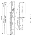
- Fig. 6 shows the structure of a DAB transmission frame.
- the transmission frame includes, starting from the header side, a synchronization channel, a fast information channel (FIC) and a main service channel (MSC).
- FIC is constituted of a plurality of fast information blocks (FIBs)
- MSC is constituted of a plurality of common interleaved frames (CIFs).
- Modes 1 to 3 are defined in the specifications of DAB. Each mode has a different transmission frame duration and a different number of FIBs and CIFs in one transmission frame. For example, the mode 1 has one transmission frame duration of 96 ms and 12 FIBs and 4 CIFs in each transmission frame.
- Fig. 7 is an illustrative diagram of a DAB service structure.
- An ensemble having an ensemble label "DAB ENSEMBLE ONE” contains a plurality of services such as those with a service label "ALPHA 1 RADIO", a service label “BETA RADIO” and a service label “ALPHA 2 RADIO”.
- a user can listen a selected service from the DAB radio 10.
- the "alpha 1 radio" service has one main service component and two subsidiary service components.
- the main service component is an audio component
- the subsidiary service components are a traffic message channel (TMC) component and a service information (SI) component.
- TMC traffic message channel
- SI service information
- the audio component and SI component are transmitted via different sub-channels in MSC, whereas the TMC component is transmitted via a fast information data channel (FIDC) in FIC.
- FIDC fast information data channel
- the "beta radio" service has two service components, an audio component and a secondary audio component both of which are transmitted via sub-channels of MSC.
- the "alpha 2 radio” service has the same TMC and SI components as the "alpha 1 radio". Depending upon the switching, the "alpha 2 radio” may have the same audio component as the "alpha 1 radio".
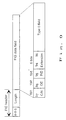
- FIG. 8 shows the structure of FIB.
- FIB is constituted of 256 bits forming a front FIB data field of 30 bytes and a rear CRC (cyclic redundancy check) word of 16 bits.
- the FIB field is constituted of a plurality of fast information groups (FIGs), one end marker and one padding (insertion of "0" into remaining bits in order for the FIB data field have 30 bytes), from the head to the end in this field.
- FIG constitutes a useful data field.
- Each FIG is constituted of an FIG type field, a length field (indicating the bit length of the following FIG data field) and an FIG data field, from the head to the end in FIG.
- the FIG type and length constitute an FIG header.
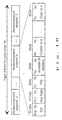
- FIG. 9 shows the structure of the FIG data field of an FIG type 0 (000 in 3-bit binary representation).
- the FIG data field is constituted of a current/next (C/N) field, another ensemble field (OE), a program/data (P/D) field, an extension filed and a type 0 field, sequentially from the head thereof.
- C/N indicates the version number of the type 0 field.
- OE is used if the extension is 12, 16, 17, 21, 24 or 30.
- SId service identifier
- Fig. 10 shows the structure of the type 0 field of FIG shown in Fig. 9 and having an extension of 18 (hereinafter, each FIG is represented by the FIG type and extension, such as FIG0/18).
- the type 0 field is constituted of a plurality of announcement support fields, announcement corresponding interrupt.
- Each announcement support field includes an SId, announcement support flags (Asu flags), a cluster number, and cluster IDs.
- Sid identifies the type of service.
- Each bit of the announcement flags corresponds to the type of interrupt information (e.g., alarm interrupt information corresponds to the 0th bit).
- the cluster ID identifies the cluster to which Sid belongs. If SId has the same cluster ID, it shares the interrupt information with another SId.
- Fig. 11 shows the structure of the type 0 field of FIG shown in Fig. 9 and having an extension of 19 (FIG0/19).
- the type 0 field is constituted of a plurality of announcement switching fields each including announcement switching flags (Asw flags), a cluster ID, a sub-channel ID (SubChid) and the like.
- Each bit of the announcement switching flags has the same meaning as that of the announcement flags of FIG0/18, and corresponds to the type of interrupt information.
- the cluster ID identifies the cluster, and the sub-channel ID identifies the sub-channel which transmits the interrupt information of the cluster. If FIG0/19 is received, it means an occurrence of an announcement (interrupt). An interrupt occurs when FIG0/18 or FIG0/19 is received, and it can know which sub-channel has the contents of the interrupt information.
- Fig. 1 is a flow chart illustrating an interrupt process allocation routine.
- Step S60 it is checked whether an interrupt request occurs. If YES, the flow advances to Step S62, whereas if NO, the flow returns to Step S60.
- Step S62 it is checked whether the interrupt is alarm information. If YES, the flow advances to Step S86 to perform an alarm interrupt process, whereas if NO, the flow advances to Step S64.
- Step S64 it is checked whether the interrupt function is on, i.e., whether the user admits to accept the interrupt information. If YES, the flow advances to Step S66, whereas if NO, the flow returns to Step S60.
- Step S66 it is checked whether the interrupt mode is an automatic mode.
- Step S72 it is checked whether an interrupt is accepted only from DAB. If YES, the flow advances to Step S76, whereas if NO, the flow advances to Step S70.
- Step S70 it is checked whether the interrupt mode is RDS only, i.e., whether an interrupt is accepted only from RDS. If YES, the flow advances to Step S82, whereas if NO, this routine is terminated.
- Step S72 it is checked whether CD is being played (under reproduction). If YES, the flow advances to Step S74, whereas if NO, the flow advances to Step S78.
- Step S74 it is checked whether the band received before the reproduction of CD is DAB or RDS. If DAB, the flow advances to Step S76, whereas if RDS, the flow advances to Step S80. At Step S76 it is checked whether the interrupt is a DAB interrupt. If YES, the flow advances to Step S84, whereas if NO, the flow returns to Step S60. At Step S78 it is checked whether the currently received band is DAB or RDS. If DAB, the flow advances to Step S76, whereas if RDS, the flow advances to Step S80. At Sep S80 it is checked whether the interrupt if a RDS interrupt request. If YES, the flow advances to Step S82, whereas if NO, the flow returns to Step S60. At Step S82 the RDS interrupt process is performed, and at Step S84 the DAB interrupt process is performed.
- Step S72 it is checked whether the interrupt is RDS or DAB interrupt. If RDS interrupt, the RDS interrupt process is performed at Step S82, whereas if DAB interrupt, the DAB interrupt process is performed at S82.
- Fig. 2 is a flow chart illustrating the interrupt mode switching routine.
- Step S90 it is checked whether the current mode is an interrupt switching mode.
- Step S92 it is checked whether the feed key is operated upon. In Fig. 3, right and left two feed keys are provided. The right feed key is operated at Step S92. If YES, the flow advances to Step S94, whereas if NO, this routine is terminated.
- Step S94 it is checked whether the state before the feed key is operated upon is the automatic mode. If YES, the flow advances to Step S98 to switch to a DAB-only mode, whereas if NO, the flow advances to Step S96.
- Step S96 it is checked whether the state before the feed key is operated upon is the DAB-only mode. If YES, the flow advances to Step S100 to switch to an RDS-only mode, whereas if NO, the flow advances to Step S102 to switch to the automatic mode.
- Fig. 3 shows the details of the key 30 and the change in display of the display unit 32 when a feed key is operated upon during the interrupt switching mode.
- the key 30 has right and left feed keys. Each time the feed key is operated upon, the display on the display unit 32 is switched in the counter-clockwise or clockwise direction between the automatic mode, DAB-only mode and RDS-only mode.
Abstract
Description
Claims (6)
- A radio receiver (40) capable of receiving signals transmitted from different transmission systems, each signal containing audio data and interrupt information data, wherein:during the reproduction of the audio data of a program of a predetermined transmission system, a signal of the predetermined transmission system and a signal of another transmission system are both received and the interrupt information data contained in the signals of the predetermined transmission system and the other transmission system is reproduced into audible sounds.
- A radio receiver (40) capable of receiving signals transmitted from different transmission systems, each signal containing audio data and interrupt information data, wherein:under the operation of an audio reproducer, signals of different transmission system are received and the interrupt information data contained in the signal of each transmission system is reproduced into audible sounds.
- A radio receiver according to claim 1 or 2, comprising:(a) selecting means (30) for selecting one or a plurality of transmission systems and allowing to output the interrupt information data; and(b) audio output means (46) for outputting the interrupt information data contained in a signal of the transmission system selected by said selecting means (30) in audible sounds.
- A radio receiver according to claim 3, wherein said audio output means (46) outputs the interrupt information data of a predetermined type in audible sounds irrespective of the selection by said selecting means (30).
- A radio receiver according to claim 3 or 4, further comprising interrupt mode display means (32) for displaying an interrupt mode of the transmission system selected by said selecting means (30).
- A radio receiver according to any one of claims 3 to 5, further comprising interrupt display means (32) for displaying the state of interrupt while said audio output means (46) outputs the interrupt information in audible sounds.
Applications Claiming Priority (3)
| Application Number | Priority Date | Filing Date | Title |
|---|---|---|---|
| JP2448997 | 1997-01-24 | ||
| JP02448997A JP3466407B2 (en) | 1997-01-24 | 1997-01-24 | Broadcast receiver |
| JP24489/97 | 1997-01-24 |
Publications (3)
| Publication Number | Publication Date |
|---|---|
| EP0865175A2 true EP0865175A2 (en) | 1998-09-16 |
| EP0865175A3 EP0865175A3 (en) | 2000-05-10 |
| EP0865175B1 EP0865175B1 (en) | 2004-10-06 |
Family
ID=12139609
Family Applications (1)
| Application Number | Title | Priority Date | Filing Date |
|---|---|---|---|
| EP19980100073 Expired - Lifetime EP0865175B1 (en) | 1997-01-24 | 1998-01-05 | Radio receiver capable of receiving signals from a plurality of transmission systems such as Digital Audio Broadcast (DAB) and Radio Data System (RDS) |
Country Status (3)
| Country | Link |
|---|---|
| EP (1) | EP0865175B1 (en) |
| JP (1) | JP3466407B2 (en) |
| DE (2) | DE69826751T2 (en) |
Cited By (5)
| Publication number | Priority date | Publication date | Assignee | Title |
|---|---|---|---|---|
| EP1227608A2 (en) * | 2001-01-26 | 2002-07-31 | Robert Bosch Gmbh | Method for switching a broadcast receiver to a different broadcast transmission with the same audio content |
| EP1233556A1 (en) * | 2001-02-16 | 2002-08-21 | Sony International (Europe) GmbH | Receiver for receiving broadcast signals, comprising two tuners, for receiving a broadcast signal transmitted on two different broadcast frequencies or using two different broadcast systems |
| KR100423888B1 (en) * | 2000-12-26 | 2004-03-24 | 주식회사 아미시스 | Apparatus for Receiving Meta Information, Apparatus and Method for Providing Service Using Meta Information |
| GB2395407A (en) * | 2002-11-13 | 2004-05-19 | Bosch Gmbh Robert | Data format of different fields for Digital Audio Broadcasting signals |
| US10140084B2 (en) | 2000-10-12 | 2018-11-27 | Bose Corporation | Interactive sound reproducing |
Families Citing this family (1)
| Publication number | Priority date | Publication date | Assignee | Title |
|---|---|---|---|---|
| KR100807756B1 (en) | 2005-06-07 | 2008-02-28 | 이용종 | A receiver for terrstrial/satellite DMB signal and the contol method thereof |
Citations (5)
| Publication number | Priority date | Publication date | Assignee | Title |
|---|---|---|---|---|
| EP0283708A2 (en) * | 1987-03-23 | 1988-09-28 | Robert Bosch Gmbh | Radio receiver with two traffic radio decoders |
| WO1993009615A1 (en) * | 1991-11-01 | 1993-05-13 | Telefunken Fernseh Und Rundfunk Gmbh | Radio transmission system and radio receiver |
| EP0593024A2 (en) * | 1992-10-12 | 1994-04-20 | CLARION Co., Ltd. | Electronic device |
| DE4408930A1 (en) * | 1994-03-16 | 1995-09-21 | Stabo Elektronik Gmbh & Co Kg | Combination audio system suitable for motor vehicle installation |
| EP0725503A1 (en) * | 1995-02-03 | 1996-08-07 | Robert Bosch Gmbh | Method for receiving and outputting broadcast programmes with supplementary digital information and broadcast receiver for displaying digital information of other broadcast programmes |
-
1997
- 1997-01-24 JP JP02448997A patent/JP3466407B2/en not_active Expired - Fee Related
-
1998
- 1998-01-05 EP EP19980100073 patent/EP0865175B1/en not_active Expired - Lifetime
- 1998-01-05 DE DE1998626751 patent/DE69826751T2/en not_active Expired - Lifetime
- 1998-01-05 DE DE1998100073 patent/DE865175T1/en active Pending
Patent Citations (5)
| Publication number | Priority date | Publication date | Assignee | Title |
|---|---|---|---|---|
| EP0283708A2 (en) * | 1987-03-23 | 1988-09-28 | Robert Bosch Gmbh | Radio receiver with two traffic radio decoders |
| WO1993009615A1 (en) * | 1991-11-01 | 1993-05-13 | Telefunken Fernseh Und Rundfunk Gmbh | Radio transmission system and radio receiver |
| EP0593024A2 (en) * | 1992-10-12 | 1994-04-20 | CLARION Co., Ltd. | Electronic device |
| DE4408930A1 (en) * | 1994-03-16 | 1995-09-21 | Stabo Elektronik Gmbh & Co Kg | Combination audio system suitable for motor vehicle installation |
| EP0725503A1 (en) * | 1995-02-03 | 1996-08-07 | Robert Bosch Gmbh | Method for receiving and outputting broadcast programmes with supplementary digital information and broadcast receiver for displaying digital information of other broadcast programmes |
Cited By (8)
| Publication number | Priority date | Publication date | Assignee | Title |
|---|---|---|---|---|
| US10140084B2 (en) | 2000-10-12 | 2018-11-27 | Bose Corporation | Interactive sound reproducing |
| US10481855B2 (en) | 2000-10-12 | 2019-11-19 | Bose Corporation | Interactive sound reproducing |
| KR100423888B1 (en) * | 2000-12-26 | 2004-03-24 | 주식회사 아미시스 | Apparatus for Receiving Meta Information, Apparatus and Method for Providing Service Using Meta Information |
| EP1227608A2 (en) * | 2001-01-26 | 2002-07-31 | Robert Bosch Gmbh | Method for switching a broadcast receiver to a different broadcast transmission with the same audio content |
| EP1227608A3 (en) * | 2001-01-26 | 2003-01-02 | Robert Bosch Gmbh | Method for switching a broadcast receiver to a different broadcast transmission with the same audio content |
| EP1233556A1 (en) * | 2001-02-16 | 2002-08-21 | Sony International (Europe) GmbH | Receiver for receiving broadcast signals, comprising two tuners, for receiving a broadcast signal transmitted on two different broadcast frequencies or using two different broadcast systems |
| GB2395407A (en) * | 2002-11-13 | 2004-05-19 | Bosch Gmbh Robert | Data format of different fields for Digital Audio Broadcasting signals |
| GB2395407B (en) * | 2002-11-13 | 2005-02-02 | Bosch Gmbh Robert | Data format,digital radio broadcasting signal,assigned information system and method of operating the same |
Also Published As
| Publication number | Publication date |
|---|---|
| EP0865175A3 (en) | 2000-05-10 |
| DE69826751T2 (en) | 2005-10-06 |
| DE69826751D1 (en) | 2004-11-11 |
| EP0865175B1 (en) | 2004-10-06 |
| JP3466407B2 (en) | 2003-11-10 |
| JPH10209985A (en) | 1998-08-07 |
| DE865175T1 (en) | 1999-04-22 |
Similar Documents
| Publication | Publication Date | Title |
|---|---|---|
| JP3360399B2 (en) | Digital audio broadcasting receiver | |
| EP0843429A2 (en) | Broadcast receiver for receiving digital audio broadcast comprising supplementary data | |
| JP3204282B2 (en) | Receiving machine | |
| US5734780A (en) | Recording/reproducing device which receives an FM multiplexed signal comprising a subcarrier or a darc signal and outputs traffic information after detecting an intermission | |
| EP0865175B1 (en) | Radio receiver capable of receiving signals from a plurality of transmission systems such as Digital Audio Broadcast (DAB) and Radio Data System (RDS) | |
| EP0905931A2 (en) | Receiver for Digital Audio Broadcast comprising a plurality of decoding means for independently decoding a plurality of programmes | |
| JPH10209983A (en) | Automatic sound recording/reproducing device for dab receiver | |
| JP3529976B2 (en) | Radio receiver | |
| JPH098751A (en) | Method and device for fetching and recording broadcast program | |
| EP0833468B1 (en) | Receiver for receiving mulliplexed broadcast programmes, comprising audio data and supplementary broadcast data | |
| JP2001044867A (en) | Broadcast receiver and notice method notifying change in program configuration | |
| JPH08265199A (en) | Receiver for broadcasting to synchronize required broadcasting station and its method | |
| JPH11234154A (en) | Multiplex broadcast receiver | |
| KR100478413B1 (en) | Audio signal recording and reproducing apparatus | |
| KR100511553B1 (en) | Digital multimedia broadcasting receiver and operating methode thereof | |
| JP2925978B2 (en) | Multiplex information receiver | |
| JP3593254B2 (en) | Digital broadcast receiver | |
| KR0172701B1 (en) | Car audio recording traffic information broadcasting and its controlling method thereof | |
| JP3290083B2 (en) | Broadcast receiver | |
| JPH11331004A (en) | Digital broadcast recording system and digital radio broadcast recording system | |
| JP2000105989A (en) | Av system | |
| JP2000236272A (en) | Receiver for audio broadcasting | |
| JPH11261501A (en) | Digital broadcasting receiver | |
| JPH11213642A (en) | Dab receiver | |
| JP2000134119A (en) | Radio receiver |
Legal Events
| Date | Code | Title | Description |
|---|---|---|---|
| PUAI | Public reference made under article 153(3) epc to a published international application that has entered the european phase |
Free format text: ORIGINAL CODE: 0009012 |
|
| AK | Designated contracting states |
Kind code of ref document: A2 Designated state(s): DE GB |
|
| AX | Request for extension of the european patent |
Free format text: AL;LT;LV;MK;RO;SI |
|
| RTI1 | Title (correction) | ||
| DET | De: translation of patent claims | ||
| PUAL | Search report despatched |
Free format text: ORIGINAL CODE: 0009013 |
|
| AK | Designated contracting states |
Kind code of ref document: A3 Designated state(s): AT BE CH DE DK ES FI FR GB GR IE IT LI LU MC NL PT SE |
|
| AX | Request for extension of the european patent |
Free format text: AL;LT;LV;MK;RO;SI |
|
| 17P | Request for examination filed |
Effective date: 20001106 |
|
| AKX | Designation fees paid |
Free format text: DE GB |
|
| 17Q | First examination report despatched |
Effective date: 20011211 |
|
| GRAP | Despatch of communication of intention to grant a patent |
Free format text: ORIGINAL CODE: EPIDOSNIGR1 |
|
| GRAS | Grant fee paid |
Free format text: ORIGINAL CODE: EPIDOSNIGR3 |
|
| GRAA | (expected) grant |
Free format text: ORIGINAL CODE: 0009210 |
|
| AK | Designated contracting states |
Kind code of ref document: B1 Designated state(s): DE GB |
|
| REG | Reference to a national code |
Ref country code: GB Ref legal event code: FG4D |
|
| REF | Corresponds to: |
Ref document number: 69826751 Country of ref document: DE Date of ref document: 20041111 Kind code of ref document: P |
|
| PLBE | No opposition filed within time limit |
Free format text: ORIGINAL CODE: 0009261 |
|
| STAA | Information on the status of an ep patent application or granted ep patent |
Free format text: STATUS: NO OPPOSITION FILED WITHIN TIME LIMIT |
|
| 26N | No opposition filed |
Effective date: 20050707 |
|
| REG | Reference to a national code |
Ref country code: DE Ref legal event code: R082 Ref document number: 69826751 Country of ref document: DE Representative=s name: LEINWEBER & ZIMMERMANN, DE |
|
| REG | Reference to a national code |
Ref country code: DE Ref legal event code: R082 Ref document number: 69826751 Country of ref document: DE Representative=s name: LEINWEBER & ZIMMERMANN, DE Effective date: 20120430 Ref country code: DE Ref legal event code: R081 Ref document number: 69826751 Country of ref document: DE Owner name: JVC KENWOOD CORPORATION, YOKOHAMA-SHI, JP Free format text: FORMER OWNER: KABUSHIKI KAISHA KENWOOD, TOKIO/TOKYO, JP Effective date: 20120430 |
|
| PGFP | Annual fee paid to national office [announced via postgrant information from national office to epo] |
Ref country code: GB Payment date: 20130102 Year of fee payment: 16 Ref country code: DE Payment date: 20130103 Year of fee payment: 16 |
|
| REG | Reference to a national code |
Ref country code: DE Ref legal event code: R119 Ref document number: 69826751 Country of ref document: DE |
|
| REG | Reference to a national code |
Ref country code: DE Ref legal event code: R079 Ref document number: 69826751 Country of ref document: DE Free format text: PREVIOUS MAIN CLASS: H04H0001000000 Ipc: H04H0040000000 |
|
| GBPC | Gb: european patent ceased through non-payment of renewal fee |
Effective date: 20140105 |
|
| REG | Reference to a national code |
Ref country code: DE Ref legal event code: R119 Ref document number: 69826751 Country of ref document: DE Effective date: 20140801 Ref country code: DE Ref legal event code: R079 Ref document number: 69826751 Country of ref document: DE Free format text: PREVIOUS MAIN CLASS: H04H0001000000 Ipc: H04H0040000000 Effective date: 20140922 |
|
| PG25 | Lapsed in a contracting state [announced via postgrant information from national office to epo] |
Ref country code: DE Free format text: LAPSE BECAUSE OF NON-PAYMENT OF DUE FEES Effective date: 20140801 |
|
| PG25 | Lapsed in a contracting state [announced via postgrant information from national office to epo] |
Ref country code: GB Free format text: LAPSE BECAUSE OF NON-PAYMENT OF DUE FEES Effective date: 20140105 |