EP0863806B1 - Laser-directed article fabrication using hot isostatic processing - Google Patents
Laser-directed article fabrication using hot isostatic processing Download PDFInfo
- Publication number
- EP0863806B1 EP0863806B1 EP96942807A EP96942807A EP0863806B1 EP 0863806 B1 EP0863806 B1 EP 0863806B1 EP 96942807 A EP96942807 A EP 96942807A EP 96942807 A EP96942807 A EP 96942807A EP 0863806 B1 EP0863806 B1 EP 0863806B1
- Authority
- EP
- European Patent Office
- Prior art keywords
- article
- metal powder
- layer
- powder
- metal
- Prior art date
- Legal status (The legal status is an assumption and is not a legal conclusion. Google has not performed a legal analysis and makes no representation as to the accuracy of the status listed.)
- Expired - Lifetime
Links
Images



Classifications
-
- B—PERFORMING OPERATIONS; TRANSPORTING
- B22—CASTING; POWDER METALLURGY
- B22F—WORKING METALLIC POWDER; MANUFACTURE OF ARTICLES FROM METALLIC POWDER; MAKING METALLIC POWDER; APPARATUS OR DEVICES SPECIALLY ADAPTED FOR METALLIC POWDER
- B22F3/00—Manufacture of workpieces or articles from metallic powder characterised by the manner of compacting or sintering; Apparatus specially adapted therefor ; Presses and furnaces
- B22F3/12—Both compacting and sintering
- B22F3/1208—Containers or coating used therefor
- B22F3/1258—Container manufacturing
- B22F3/1266—Container manufacturing by coating or sealing the surface of the preformed article, e.g. by melting
-
- B—PERFORMING OPERATIONS; TRANSPORTING
- B22—CASTING; POWDER METALLURGY
- B22F—WORKING METALLIC POWDER; MANUFACTURE OF ARTICLES FROM METALLIC POWDER; MAKING METALLIC POWDER; APPARATUS OR DEVICES SPECIALLY ADAPTED FOR METALLIC POWDER
- B22F10/00—Additive manufacturing of workpieces or articles from metallic powder
- B22F10/20—Direct sintering or melting
- B22F10/28—Powder bed fusion, e.g. selective laser melting [SLM] or electron beam melting [EBM]
-
- B—PERFORMING OPERATIONS; TRANSPORTING
- B29—WORKING OF PLASTICS; WORKING OF SUBSTANCES IN A PLASTIC STATE IN GENERAL
- B29C—SHAPING OR JOINING OF PLASTICS; SHAPING OF MATERIAL IN A PLASTIC STATE, NOT OTHERWISE PROVIDED FOR; AFTER-TREATMENT OF THE SHAPED PRODUCTS, e.g. REPAIRING
- B29C64/00—Additive manufacturing, i.e. manufacturing of three-dimensional [3D] objects by additive deposition, additive agglomeration or additive layering, e.g. by 3D printing, stereolithography or selective laser sintering
- B29C64/10—Processes of additive manufacturing
- B29C64/141—Processes of additive manufacturing using only solid materials
- B29C64/153—Processes of additive manufacturing using only solid materials using layers of powder being selectively joined, e.g. by selective laser sintering or melting
-
- B—PERFORMING OPERATIONS; TRANSPORTING
- B33—ADDITIVE MANUFACTURING TECHNOLOGY
- B33Y—ADDITIVE MANUFACTURING, i.e. MANUFACTURING OF THREE-DIMENSIONAL [3D] OBJECTS BY ADDITIVE DEPOSITION, ADDITIVE AGGLOMERATION OR ADDITIVE LAYERING, e.g. BY 3D PRINTING, STEREOLITHOGRAPHY OR SELECTIVE LASER SINTERING
- B33Y10/00—Processes of additive manufacturing
-
- B—PERFORMING OPERATIONS; TRANSPORTING
- B33—ADDITIVE MANUFACTURING TECHNOLOGY
- B33Y—ADDITIVE MANUFACTURING, i.e. MANUFACTURING OF THREE-DIMENSIONAL [3D] OBJECTS BY ADDITIVE DEPOSITION, ADDITIVE AGGLOMERATION OR ADDITIVE LAYERING, e.g. BY 3D PRINTING, STEREOLITHOGRAPHY OR SELECTIVE LASER SINTERING
- B33Y70/00—Materials specially adapted for additive manufacturing
-
- B—PERFORMING OPERATIONS; TRANSPORTING
- B22—CASTING; POWDER METALLURGY
- B22F—WORKING METALLIC POWDER; MANUFACTURE OF ARTICLES FROM METALLIC POWDER; MAKING METALLIC POWDER; APPARATUS OR DEVICES SPECIALLY ADAPTED FOR METALLIC POWDER
- B22F10/00—Additive manufacturing of workpieces or articles from metallic powder
- B22F10/30—Process control
- B22F10/32—Process control of the atmosphere, e.g. composition or pressure in a building chamber
-
- B—PERFORMING OPERATIONS; TRANSPORTING
- B22—CASTING; POWDER METALLURGY
- B22F—WORKING METALLIC POWDER; MANUFACTURE OF ARTICLES FROM METALLIC POWDER; MAKING METALLIC POWDER; APPARATUS OR DEVICES SPECIALLY ADAPTED FOR METALLIC POWDER
- B22F12/00—Apparatus or devices specially adapted for additive manufacturing; Auxiliary means for additive manufacturing; Combinations of additive manufacturing apparatus or devices with other processing apparatus or devices
- B22F12/40—Radiation means
- B22F12/41—Radiation means characterised by the type, e.g. laser or electron beam
-
- B—PERFORMING OPERATIONS; TRANSPORTING
- B22—CASTING; POWDER METALLURGY
- B22F—WORKING METALLIC POWDER; MANUFACTURE OF ARTICLES FROM METALLIC POWDER; MAKING METALLIC POWDER; APPARATUS OR DEVICES SPECIALLY ADAPTED FOR METALLIC POWDER
- B22F12/00—Apparatus or devices specially adapted for additive manufacturing; Auxiliary means for additive manufacturing; Combinations of additive manufacturing apparatus or devices with other processing apparatus or devices
- B22F12/40—Radiation means
- B22F12/44—Radiation means characterised by the configuration of the radiation means
-
- B—PERFORMING OPERATIONS; TRANSPORTING
- B22—CASTING; POWDER METALLURGY
- B22F—WORKING METALLIC POWDER; MANUFACTURE OF ARTICLES FROM METALLIC POWDER; MAKING METALLIC POWDER; APPARATUS OR DEVICES SPECIALLY ADAPTED FOR METALLIC POWDER
- B22F12/00—Apparatus or devices specially adapted for additive manufacturing; Auxiliary means for additive manufacturing; Combinations of additive manufacturing apparatus or devices with other processing apparatus or devices
- B22F12/40—Radiation means
- B22F12/49—Scanners
-
- B—PERFORMING OPERATIONS; TRANSPORTING
- B22—CASTING; POWDER METALLURGY
- B22F—WORKING METALLIC POWDER; MANUFACTURE OF ARTICLES FROM METALLIC POWDER; MAKING METALLIC POWDER; APPARATUS OR DEVICES SPECIALLY ADAPTED FOR METALLIC POWDER
- B22F12/00—Apparatus or devices specially adapted for additive manufacturing; Auxiliary means for additive manufacturing; Combinations of additive manufacturing apparatus or devices with other processing apparatus or devices
- B22F12/90—Means for process control, e.g. cameras or sensors
-
- B—PERFORMING OPERATIONS; TRANSPORTING
- B22—CASTING; POWDER METALLURGY
- B22F—WORKING METALLIC POWDER; MANUFACTURE OF ARTICLES FROM METALLIC POWDER; MAKING METALLIC POWDER; APPARATUS OR DEVICES SPECIALLY ADAPTED FOR METALLIC POWDER
- B22F3/00—Manufacture of workpieces or articles from metallic powder characterised by the manner of compacting or sintering; Apparatus specially adapted therefor ; Presses and furnaces
- B22F3/12—Both compacting and sintering
- B22F3/14—Both compacting and sintering simultaneously
- B22F3/15—Hot isostatic pressing
-
- Y—GENERAL TAGGING OF NEW TECHNOLOGICAL DEVELOPMENTS; GENERAL TAGGING OF CROSS-SECTIONAL TECHNOLOGIES SPANNING OVER SEVERAL SECTIONS OF THE IPC; TECHNICAL SUBJECTS COVERED BY FORMER USPC CROSS-REFERENCE ART COLLECTIONS [XRACs] AND DIGESTS
- Y02—TECHNOLOGIES OR APPLICATIONS FOR MITIGATION OR ADAPTATION AGAINST CLIMATE CHANGE
- Y02P—CLIMATE CHANGE MITIGATION TECHNOLOGIES IN THE PRODUCTION OR PROCESSING OF GOODS
- Y02P10/00—Technologies related to metal processing
- Y02P10/25—Process efficiency
Definitions
- This invention is in the field of the manufacturing of solid three-dimensional articles, and is more specifically directed to the additive fabrication of metal articles such as parts and mold dies.
- the selective laser sintering technology has enabled the direct manufacture of three-dimensional articles of high resolution and dimensional accuracy from a variety of materials including wax, polycarbonate, nylon, other plastics, and composite materials such as polymer coated metals and ceramics. Wax parts may be used in the generation of tooling by way of the well-known "lost wax" process. Examples of composite powder materials are described in U.S. Patent No. 4,944,817, U.S. Patent No. 5,156,697, and in U.S. Patent No. 5,284,695, all assigned to Board of Regents, The University of Texas System.
- the production of metal parts by selective laser sintering conventionally uses a powder of metal particles coated with a polymer, from which a "green" part is fabricated by selective laser sintering of the polymer coating to binds the particles to one another.
- the green part is then heated to a temperature above the decomposition temperature of the polymer, which both drives off the polymer and also binds the metal substrate particles to one another to form the metal article.
- the article is a mold die for injection molding
- the die is also impregnated with another metal, for example copper, to add strength, wear resistance, and tooling life.
- composite polymer-metal parts or tooling may be formed without subjecting the green part to a post-process anneal.
- the green parts formed by the selective laser sintering of a polymer-coated metal powder are impregnated with a liquid resin.
- the resin is cross-linked, either at room temperature or at an elevated temperature, depending upon the resin chemistry, resulting in near-fully dense composite articles.
- the selective laser sintering technology has also been applied to the direct fabrication of articles, such as molds, from metal powders without a binder.
- metal powder reportedly used in such direct fabrication include two-phase metal powders of the copper-tin, copper-solder (the solder being 70% lead and 30% tin), and bronze-nickel systems.
- the metal articles formed by selective laser sintering in these ways have been quite dense, for example having densities of up to 70-80% of fully dense (prior to any infiltration). However, some porosity still remains in these metal articles, thus limiting their structural strength and thus the utility of the articles. For example, the less-than-fully dense articles so fabricated, even when subsequently infiltrated by a molten metal, will not have the same length of life, when used as injection mold dies, as will machined dies from solid metal substrates. Such articles are also not useful as actual working parts in machinery, in comparison to machined parts.
- Klocke, et al. "Rapid Metal Prototyping and Tooling", EARP-Newsletter , Vol. 6, (July 1995) and is referred to as "laser generating”.
- the powder is not dispensed in a layer-wise fashion as in the case of selective laser sintering, but is instead fed into the melting pool produced by the location at which the laser is focused.
- the fed powder is then bonded to the article at that point, with additional powder fed thereto to further build up the article.
- the Klocke et al. article indicates that thin-walled articles have been formed from metal powders (iron and cobalt base metals) using the laser generating technology.
- HIP hot isostatic pressing
- the softened metal of the workpiece (and can) is thus isotropically squeezed, eliminating any porosity in the article.
- the can is then conventionally removed from the article, for example by machining or by etching.
- the fabrication of the "can" is generally quite difficult, when accomplished by conventional techniques such as machining. As such, the dimensional resolution and shape-complexity of the articles produced by HIP processes are typically limited.
- One embodiment in accordance with the invention provides a process of fabricating an article in which laser directed techniques are used to produce a metal article surrounded by a gas-impervious skin, preferably of the same metal material.
- the article is fabricated, in the example of selective laser sintering, by scanning the skin portion of the article in each layer of metal powder with increased laser power or reduced scan speed, so that the density of the sintered portion of the laser in the skin is much increased from that of the article being formed while minimizing the thermal gradients in the system.
- the article is formed in layer-wise fashion and, after removal from the surrounding unfused metal powder, is then subjected to a conventional hot isostatic pressing (HIP) process to densify the article.
- the gas-impervious skin in the selective laser sintered article serves as the "can" in the HIP process, and may either be removed by machining after densification or may remain as the outer layer of the article.
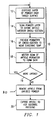
- the method begins with process 10, in which a three-dimensional metal article is fabricated by the selective laser sintering of a metal powder in such a manner that a gas-impervious skin surrounds the body of the article, where the skin serves as the "can" in a subsequent hot isostatic pressing process.
- selective laser sintering process 10 includes a series of steps that are repetitively performed to fabricate the body of the article surrounded by an integrally-formed gas-impervious skin.
- Process 10 is preferably performed in a selective laser sintering system, such as the SINTERSTATION 2000 system available from DTM Corporation, in which the various steps of process 10 are effected in a single process chamber.
- a selective laser sintering system such as the SINTERSTATION 2000 system available from DTM Corporation
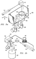
- selective laser sintering system 100 includes a chamber 102 (front doors and the top of chamber 102 not shown in Figure 2a, for purposes of clarity) within which selective laser sintering process 10 takes place.
- Target surface 104 refers to the top surface of heat-fusible powder (including portions previously sintered, if present) disposed on part piston 106; the sintered and unsintered powder disposed on part piston 106 will be referred to herein as part bed 107.
- the vertical motion of part piston 106 is controlled by motor 108.
- Laser 110 provides a beam which is directed by scanning system 142 in the manner described in the U.S. Patents referred to hereinabove and as shown in Figure 2b.
- FIG. 2b illustrates laser 110 and scanning system 142.
- Laser 110 includes, in addition to a laser itself, such conventional control elements as described in the above-referenced U.S. Patent No. 4,863,538, for example a safety shutter, a front mirror assembly, and focusing elements such as diverging and converging lenses.
- the type of laser 110 used is, of course, dependent upon many factors and in particular upon the type of powder that is to be sintered.
- a preferred laser is a 150 watt Nd/YAG type laser, preferably with controllable power output.
- Laser 110 is preferably controllable to be modulated on and off; while on, laser 110 produces laser beam 105 which travels generally along the path shown by the arrows in Figure 2b.
- Computer 140 and scanning system 142 are also included for controlling the direction of the laser beam as it impinges target surface 104.
- computer 140 includes a microprocessor for controlling laser 110 and further includes a CAD/CAM system for generating the data that defines the dimensions of the article being produced.
- a conventional personal computer workstation such as a personal computer based on a Pentium-class microprocessor and including floating point capabilities, is suitable for use as computer 140 in the preferred embodiment of the invention.
- Scanning system 142 includes prism 144 for redirecting the path of travel of laser beam 105; the number of prisms 144 necessary for directing laser beam 105 to the proper location is based on the physical layout of the apparatus. Alternatively, as is well known in the art, one or more fixed mirrors can be used in place of prism 144 for directing laser beam 105, depending upon the particular layout of system 100.
- Scanning system 142 further includes a pair of mirrors 146, 147 which are driven by respective galvanometers 148, 149. Galvanometers 148, 149 are coupled to their respective mirrors 146, 147 to selectively orient the mirrors 146, 147 and control the aim of laser beam 105.
- Galvanometers 148, 149 are mounted perpendicularly to one another so that mirrors 146, 147 are mounted nominally at a right angle relative to one another.
- a function generator driver in scanning system 142 controls the movement of galvanometers 148,149 to control the aim of laser beam 105 within target surface 104, in conjunction with its on and off modulation controlled by computer 140, according to CAD/CAM data stored within computer 140 that defines the cross-section of the article to be formed in the layer of powder at target surface 104.
- alternative scanning systems may be used in place of scanning system 142 described hereinabove, including such apparatus as acoustic-optic scanners, rotating polygonal mirrors, and resonant mirror scanners.
- delivery of the metal heat-fusible powder is accomplished in system 100 by way of powder, or feed, piston 114, controlled by motor 116, in combination with counter-rotating roller 118.
- counter-rotating roller 118 transfers the powder lifted above the floor of chamber 102 to target surface 104 in a uniform and level fashion. It may be preferred to provide two powder pistons 114 on either side of part piston 106, for purposes of efficient and flexible powder deliver, as used in the SINTERSTATION 2000 system available from DTM Corporation.
- selective laser sintering process 10 begins by system 100 performing process 12 to dispense a layer of metal powder over target surface 104.
- powder is delivered by feed piston 114 moving upwardly to place a volume of powder into chamber 102.
- Roller 118 (preferably provided with a scraper to prevent buildup, such scraper not shown in Figure 2a for clarity) spreads the powder within chamber 102 and over target surface 104 by its translation from feed piston 114 toward and across target surface 104 at the surface of part bed 107 above part piston 106, in the manner described in the above-incorporated U.S. Patent No. 5,017,753.
- target surface 104 (whether or not a prior layer is disposed thereat) is preferably below the floor of chamber 102 by a small amount, for example 5 mils, to define the thickness of the laser of powder to now be processed. It is preferable, for smooth and thorough distribution of the powder, that the amount of powder provided by feed piston 114 be greater than that which can be accepted by part piston 106, so that some excess powder will result from the motion of roller 118 across target surface 104; this may be accomplished by the raising of feed piston 114 above the floor of chamber 102 by a greater distance that the distance below the floor of chamber 102 that part piston 106 is lowered (e.g., 10 mils versus 5 mils). It is also preferable to slave the counter-rotation of roller 118 to the translation of roller 118 within chamber 102, so that the ratio of rotational speed to translation speed is constant
- Target surface 104 is typically a previously dispensed layer of powder, whether or not portions of the article have been formed therein; alternatively, as will be described in further detail hereinbelow, target surface 104 may be a solid substrate that is in place in part piston 106 and upon which the article will be formed.
- the powder dispensed in process 12 is a metal powder of the material from which the eventual fully-dense article is to be fabricated.
- the powder useful according to this embodiment of the invention may be from a wide range of materials, specific examples of which include powders of superalloys (e.g., InCoNel), carbon steel, stainless steel, copper-steel, nickel-bronze steel, titanium alloys, nickel-based alloys, and mixtures of metals (e.g., a mixture of bronze and nickel powders). It is contemplated that this embodiment of the invention will allow a wide range of metal materials to be used in the fabrication of fully-dense metal articles, due to its minimization of the volume of powder required to be fully sintered.
- powders of superalloys e.g., InCoNel
- carbon steel e.g., stainless steel, copper-steel, nickel-bronze steel, titanium alloys, nickel-based alloys, and mixtures of metals (e.g., a mixture of bronze and nickel powders).
- this embodiment of the invention will allow a wide range of metal materials to be used in the fabrication of fully-dense metal articles,
- FIG. 3a illustrates, in plan view, an exemplary layer 50 of unfused powder in which interior article portions 52a, 52b are formed by way of process 14.
- the shapes of interior article portions 52a 52b as formed in a particular layer of powder 50 may be relatively complex, due to the ability of laser 110 to accurately define a cross-section of the article based upon the CAD representation thereof.
- process 14 is preferably performed in such a manner as to bind the particles of powder in the cross-section to one another, but not to such an extent as to form a fully-dense metal portion thereat.
- interior article portions 52a, 52b may be formed by way of interleaved overlapping or non-overlapping scans of laser beam 105 thereacross in a raster scan fashion, where laser 110 is turned on when focused on interior article portions 52a, 52b and turned off otherwise.
- laser beam 105 may be directed across interior article portions 52a, 52b in a cross-hatch pattern, where the raster scan is in one direction in a first pass, followed by raster scan in a perpendicular direction in a second pass of the same layer 50 of powder.
- interior article portions 52a, 52b be defined and solidified to some extent in process 14, to minimize shrinkage of the eventual article during hot isostatic processing; however, as noted above, interior article portions 52a, 52b should not be defined in a fully-dense state by laser beam 105 in process 14, as the thermal gradients necessary in so fabricating the article will exacerbate distortion of the article.
- the present invention minimizes such thermal distortion by minimizing the volume of the article that is formed in a dense fashion during selective laser sintering process 10.
- selective laser sintering process 10 is preferably performed under conditions in chamber 102 that are not conducive to the oxidation of the metal powder. Prevention of oxidation is particularly crucial if the powder consists of certain metals, such as titanium alloys. To accomplish this, an inert or non-oxidizing atmosphere, such as nitrogen, preferably fills chamber 102 during selective laser sintering process 10.
- process 16 is now performed by selective laser sintering system 100 to preheat portions of the powder layer 50, including at least the powder at the perimeter of interior article portions 52a, 52b.
- These portions of the powder at the perimeter of interior article portions 52a, 52b are the locations at which a gas-impervious "skin" will be formed through the operation of selective laser sintering in process 18, and as such will be the locations at which significantly higher laser energy per unit volume (relative to that applied in process 14) will be applied.
- Various approaches to performing the preheating of process 16 will be described hereinbelow, after the description of process 18 in which the gas-impervious skin is formed.
- process 18 is performed in order to form gas-impervious skin 54 at the perimeter of, and surrounding, interior article portions 52a, 52b in the layer of powder.
- Process 18 is performed by way of selective laser sintering, as in the case of process 14, but under different conditions than those used in process 14 to form the interior portions.
- the interior article portions 52a, 52b formed by process 14 will be less than fully-dense, and will thus have some porosity so as to not themselves be gas-impervious.
- the hot isostatic pressing process (HIP) that is to be subsequently performed according to the present invention requires that the exterior of the article undergoing the HIP process be gas impervious, so that pressurized gas may exert a densifying force upon the interior article 52 via skin 54. Accordingly, skin 54 is formed in process 18 around the perimeter of interior article portions 52a, 52b in layer 50, so as to have higher density than interior article portions 52.
- process 18 is preferably performed by directing laser beam 105 in a vector drawing fashion around the perimeter of interior article portions 52, in such a way as to deliver thereat a relatively higher energy per unit volume than used to form interior article portions 52.
- This increased energy may be applied simply by increasing the laser energy for process 18 relative to that used in process 14, or by reducing the scan speed so that the dwell time of laser beam 105 is greater in forming skin 54 than in forming interior article portions 52.
- skin 54 may be formed in process 18 by performing repeated overlapping vector scans of the perimeter of interior article portions 52 (where interior article portions 52 were formed by non-overlapping or cross-hatching raster scans). Any or all of these approaches may be used individually or in combination to form skin 54.
- certain real-time controls of the laser energy may be beneficial in the uniform formation of skin 54, particularly in controlling certain geometry-dependent effects.
- the energy provided to form comer 55 of skin 54 may be excessive, due to is sharpness and thus to the time that laser beam 105 must be present thereat to form skin 54.
- this process may be performed either prior to or during the formation of skin 54 in an individual layer; this is preferred according to this embodiment of the invention in order to maintain the laser power as low as possible to effect the fabrication of the gas-impervious skin while still maintaining the powder at a temperature below its caking temperature when dispensed in process 12.
- many powders, including those metal powders for which the invention is intended exhibit some amount of interparticle adherence at temperatures that are well below their sintering temperatures; the threshold temperature of this effect is referred to as the "caking" temperature of the material.
- the powder be freely flowable when dispensed in process 12, and thus below the caking temperature. Since the energy required to raise most metal powders from the caking temperature to a temperature at which fully-dense sintering may occur is significant, the pre-heating of the perimeter locations of interior article portions 52a, 52b as performed in process 16 is very useful in allowing conventional lasers 110 to perform the method according to this embodiment of the invention.
- a laser beam 61 is applied to the edge of an interior article portion 52, preferably so as to overlap into unfused powder 50 in that layer, and in advance of laser beam 63 which is sintering powder 50 at the edge of interior article 52 to form a gas-impervious skin 54 in the manner described hereinbelow.
- Beam 61 is preferably focused (or unfocused, as the case may be) to provide a large spot 60 (relative to spot 62), so that the energy per unit volume applied by beam 61 to preheat this portion of the powder is less than that applied by laser 110 in forming interior article portion 52 itself.
- the energy applied by beam 61 is preferably selected so as to heat powder 50 and the edge of interior article portion 52 to a temperature near but below the sintering temperature of the material.
- the incremental additional power applied by beam 63 to form skin 54 may be minimized, thus reducing thermal gradients in powder layer 50 in producing skin 54.
- either two lasers 110 or a laser-splitting system would be used to simultaneously generate the two laser beams 61, 63.
- the preheating of process 16 may be performed in advance of the skin formation of process 18.
- the same laser 110 may perform the preheating of process 16 as used to form interior article portions 52 and skin 54, such preheating occurring in a separate vector pass around the perimeter of interior articles 52, such as with a defocused beam 61 as shown in Figure 4.
- the thermal conduction in the layer must be sufficiently low as to allow the localized preheating performed in process 16 to remain until laser 110 returns, in focused form, to fabricate skin 54.
- preheating process 16 may be performed in a macroscopic manner, for example through the use of radiant heater 130 controlled by thermal sensors 134, 136 as shown in Figure 2a, or by the heated downdraft of gas through powder 50.
- radiant heater 130 controlled by thermal sensors 134, 136 as shown in Figure 2a
- heated downdraft of gas through powder 50 it is important to ensure that the temperature of the next powder layer being dispensed is maintained below the caking temperature, of course.
- decision 19 is performed by computer 140 to determine if additional layers in the article remain to be performed. If so, selective laser sintering process 10 continues in a layerwise fashion, repeating each of processes 12,14, 16 and 18 for additional layers of the article being formed. For example, referring back to Figure 2a, the dispensation of an additional layer of powder is performed by part piston 106 dropping by a specified distance, followed by the dispensation of powder from feed piston 114 via counter-rotating roller 118 as before. The selective laser sintering of the article is performed in the next layer, typically with a different cross-section from that in the previous layer to form the article of the desired shape.
- Selective laser sintering process 10 through its repetitive layerwise processing, thus results in interior article 52 being surrounded on all sides by skin 54, as shown in the vertical cross-section in Figure 3c.
- the shape of article 52 may be quite complex, including overhanging portions such as portion 52c which connects portions 52a, 52b (in Figure 3b); in this example, portion 52c is formed after portions 52a, 52b connected thereby.
- Selective laser sintering process 10 thus enables the formation of highly complex articles with gas-impervious skins, or cans, surrounding the article.
- article 52 is formed in such a manner as to be fully surrounded by unfused powder layers 50, on the sides, bottom and top thereof.
- some of the layers formed in selective laser sintering process 10 may have substantial skin portions 54 formed therein.
- layer L l which is the first layer having solidified portions, has only a skin portion 54 l formed therein.
- Layer L K has only a small interior article portion 52 K but a large skin portion 54 K therein.
- Top layer LT has only a large skin portion 54 T formed therein.
- the formation of these relatively large skin surfaces 54 must be taken into account in the operation of selective laser sintering system 100.
- the cumulative effect of the contiguous skin surfaces 54 is to provide a gas-impervious "can" around article 52, for use in subsequent hot isostatic pressing.
- process 20 is then performed, by way of which article 52 and skin 54 are removed from the unfused powder 50.
- This process is conventional in the field of selective laser sintering, and is commonly referred to as "rough break-out".
- Process 20 is typically performed by removing part bed 107 from system 100, transferring the entire mass of the article and powder to a different workstation, and then mechanically removing unfused powder 50 from around article 52 and skin 54. Unused powder 50 may be retained and re-used in subsequent build operations.
- HIP process 30 is performed in the manner conventional in the art, by placing article 52 and skin 54 into a pressure vessel within a furnace, to fully densify the metal article.
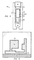
- Figure 5 illustrates HIP system 60, which is an example of the processing chamber useful in performing process 30 according to this embodiment of the invention.
- HIP system 60 includes cylindrical body 62, through a top opening of which a workpiece of article 52 surrounded by skin 54 (shown as a cylinder in this view, but which will of course have the shape formed by selective laser sintering process 10) is placed into chamber 61.
- HIP system 60 further includes heating element 68 which, together with thermal barrier 66, heats chamber 61 during the HIP process.
- Process 30 is performed by heating and pressurizing chamber 61 within HIP system 60, with the pressurizing performed with an inert gas, such as argon or helium, that is injected into chamber 61 of HIP system 60.
- an inert gas such as argon or helium
- Typical temperatures of HIP processing are on the order of 500°C to 2000°C, and pressures range from vacuum to 200 MPa; the particular temperatures and pressures used will, as is conventional in the art, depend upon the material of article 52 undergoing the HIP process.
- an article formed of a bronze/nickel mixture may be subjected to a temperature of on the order of 750 to 900°C and a pressure of on the order of 125 MPa for one to three hours.
- the temperature tolerances are typically quite small for most materials, as provided by conventional HIP processing chambers.
- the high pressure gas in chamber 61 imparts an isostatic force in an isotropic manner around skin 54. Since skin 54 is impervious to gas, however, the force imparted by the pressurized gas squeezes the outer surfaces of skin 54. Since the temperature within chamber 61 is raised to the softening temperature of the material of skin 54 and article 52, however, this force of the pressurized gas densifies article 52. After subjection of article 52 and skin 54 to this temperature and pressure condition for the appropriate duration, a fully dense metal article is provided. The HIP "can" of skin 54 may, at this point, be removed from article 52 by machining.
- skin 54 since skin 54 was formed of the same material as article 52, which is now densified via HIP process 30, skin 54 may be allowed to remain at the surface of article 52 to become part thereof. Finishing techniques may then be applied to the exterior surface of article 52, or of skin 54, as the case may be.
- shrinkage While some amount of shrinkage will occur in the densification of HIP process 30, it is contemplated that this shrinkage will be relatively small, particularly when selective laser sintering process 10 forms interior article 52 to be near-fully dense. The shrinkage may be taken into account in the CAD data base representation used in selective laser sintering process 10.
- This embodiment of the invention thus provides a fully dense three-dimensional article, such as a prototype part or a mold die, which may be fabricated of metal to have complex shapes and small feature sizes and resolution.
- the use of selective laser sintering in the fabrication of the article provide direct CAD-to-article translation, in short build times, while the use of HIP densification processing allows the selective laser sintering process to be performed at minimal power levels, thus reducing the vulnerability of the process to thermal distortion.
- the decoupling of the thermal gradient problems from the metal materials used thus serves to widen the range of metal materials which may be processed according to the preferred embodiment of the invention.
- Figure 6 illustrates, in vertical cross-section as in the case of Figure 3c, article 52 with skin 54 formed thereupon, having similar shape and dimensions as article 52 in Figure 3c.
- substrate 56 is provided within part piston 106, upon which skin layer 54 T and article 52 is formed by selective laser sintering process 10.
- article 52 is oriented upside-down relative to Figure 3c, as such orientation allows the largest planar skin layer 54 T to be in place upon substrate 56, as the largest surface is most susceptible to curL Adhesion of skin layer 54 T to substrate 56 occurs during the sintering of that layer; this adhesion will tend to counteract the effects of surface tension in cooling, reducing the curl distortion thereof.
- Substrate 56 thus must be formed of a material that is compatible with the metal of the powder, and may for example be the same material as the powder. The article will be removed from substrate 56 prior to HIP process 30.
- Figure 7 illustrates another embodiment of the invention, in which substrate 58 serves as part of the "can", together with the remainder of skin 54, eliminating the large skin surface 54 T ; in this embodiment of the invention, however, substrate 58 must be of a gas impervious material, as it will constitute part of the "can" around the article in HIP process 30.
- substrate 58 serves as part of the "can" together with the remainder of skin 54, eliminating the large skin surface 54 T ; in this embodiment of the invention, however, substrate 58 must be of a gas impervious material, as it will constitute part of the "can” around the article in HIP process 30.
- Each of these alternative embodiments thus serve to reduce thermal distortion in the eventual article.
- a laser directed process is provided to form a can for the article to be produced, within which a sinterable powder may then be dispensed which will become the article.
- FIG 8 the process according to this embodiment of the invention begins with process 70, in which a can 72 is formed by way of laser generation.
- Figure 9 schematically illustrates laser generation system 71 which includes powder dispensing system 76 and laser 78; of course, these subsystems are contained within a chamber (not shown) so that atmospheric and temperature control may be effected, similarly as described above relative to selective laser sintering system 100.
- laser generation system 71 which includes powder dispensing system 76 and laser 78; of course, these subsystems are contained within a chamber (not shown) so that atmospheric and temperature control may be effected, similarly as described above relative to selective laser sintering system 100.
- laser generation refers to a process of forming an article by dispensing powder into a location at which a laser beam is focused; the powder fuses to previously formed portions of the article at that location, so that the article is built up over time.
- This operation is shown in Figure 9, by the operation of a beam from laser 78 solidifying powder 75 being dispensed by powder dispensing system 76 at point A.
- Laser 78 will move its focused point A along the edge of can 72, building up the article as it travels.
- the direction in which laser 78 scans along the previously built-up portions of can 72 may vary, depending upon the particular circumstances and the shape thereof.
- Process 80 is then performed which, in this embodiment of the invention, involves filling can 72 with a metal powder, preferably of the same material as that used to form can 72.
- a metal powder preferably of the same material as that used to form can 72.
- the powder placed into can 72 is not densified prior to its placement into can 72, as such densification would limit its ability to fill any complex portions of can 72.
- Can 72 is then sealed, for example by way of laser sintering a top surface of powder dispensed therein using laser 78, or by attaching a metal surface thereover, as desired.
- the process according to this embodiment of the invention is then completed by subjecting can 72 containing metal powder to hot isostatic pressing, in process 90, carried out in the manner described hereinabove.
- Can 72 may then be removed from the article, or may be left in place as part of the finished product, as desired.
- the use of a directed laser beam to define the geometry and shape of the article to undergo HIP processing allows for complex part formation and high resolution construction, directly from a CAD representation of the article.
- the close fit and material compatibility of the can to the interior material also ensures that the shrinkage of the article through HIP processing is minimized, thus further improving the structural accuracy of the finished product
- the HIP processing will densify the unfused powder within the gas-impervious skin to form a dense metal article in the manner described hereinabove.
Landscapes
- Engineering & Computer Science (AREA)
- Manufacturing & Machinery (AREA)
- Chemical & Material Sciences (AREA)
- Materials Engineering (AREA)
- Physics & Mathematics (AREA)
- Mechanical Engineering (AREA)
- Optics & Photonics (AREA)
- Plasma & Fusion (AREA)
- Powder Metallurgy (AREA)
- Physical Or Chemical Processes And Apparatus (AREA)
- Laser Beam Processing (AREA)
Abstract
Description
Claims (18)
- A method of fabricating a three-dimensional metal article, comprising the steps of:dispensing a layer of metal powder at a target surface;fusing selected locations of the layer of metal powder;directing an energy beam to fuse metal powder at a perimeter locations of the selected locations of the layer of metal powder, to form a portion of a gas-impervious skin thereat;repeating the dispensing, fusing, and directing steps for a plurality of layers, with fused locations of successive layers fusing to fused locations of immediately prior layers to form an interior portion of the article within a gas-impervious skin; anddensifying the interior portion of the article by subjecting the combination of the interior portion of the article and the skin to an elevated temperature and elevated pressure.
- A method according to claim 1, wherein the fusing step comprises:directing an energy beam at selected locations of the layer of metal powder to fuse the powder thereat.
- A method according to claim 2, wherein the steps of directing an energy beam direct a laser beam at the metal powder.
- A method according to claim 3, wherein the step of directing a laser beam to fuse metal powder at perimeter locations of the article directs more energy to the perimeter locations than does the step of directing a laser beam at selected locations of the layer of metal powder.
- A method according to claim 4, wherein the step of directing a laser beam to fuse metal powder at perimeter locations of the article comprises:preheating metal powder at the perimeter locations; anddirecting a laser beam at the preheated metal powder at the perimeter locations to fuse the powder thereat.
- A method according to claim 5, wherein the preheating step comprises:heating the metal powder at the target surface.
- A method according to claim 5, wherein the preheating step comprises:directing a first laser beam along the perimeter locations of the article.
- A method according to claim 7, wherein the first laser beam delivers less energy per unit volume to the article than does the step of directing a laser beam at selected locations of the layer of metal to form the interior portion of the article.
- A method according to claim 1, wherein the step of dispensing a layer of metal powder at a target surface comprises, for a first layer, dispensing a layer of metal powder at a surface of a substrate.
- A method according to claim 9, wherein the step of directing an energy beam to fuse metal powder at perimeter locations of the article to form a gas-impervious skin around the interior portion of the article comprises, for the first layer, directing the energy beam over a selected area of the first layer of powder at the surface of the substrate to form the gas-impervious skin thereat.
- A method according to claim 9, wherein the step of fusing selected locations of the layer of metal powder into a mass comprises fusing a portion of the first layer at the surface of the substrate into a mass, so that the interior portion of the article is in contact with the surface of the substrate.
- A method according to claim 1, wherein the metal powder comprises a metal alloy.
- A method according to claim 1, wherein the metal powder comprises a steel powder.
- A method according to claim 1, wherein the metal powder comprises a mixture of a plurality of metal powders.
- A method of fabricating a three-dimensional metal article, comprising the steps of:dispensing a layer of metal powder at a target surface;directing an energy beam to fuse metal powder at selected perimeter locations of the layer of metal powder to form a portion of a gas-impervious skin, leaving the remainder of the metal powder in the layer substantially unfused;repeating the dispensing and directing steps for a plurality of layers to form the gas-impervious skin, the skin defining an interior portion containing unfused metal powder; anddensifying the dispensed metal powder in the interior of the gas-impervious skin by subjecting the combination of the skin and the interior metal powder to an elevated temperature and elevated pressure.
- A method according to claim 15, wherein the metal powder comprises a metal alloy.
- A method according to claim 15, wherein the metal powder comprises a steel powder.
- A method according to claim 15, wherein the metal powder comprises a mixture of metal powders.
Applications Claiming Priority (3)
| Application Number | Priority Date | Filing Date | Title |
|---|---|---|---|
| US563220 | 1990-08-06 | ||
| US08/563,220 US5640667A (en) | 1995-11-27 | 1995-11-27 | Laser-directed fabrication of full-density metal articles using hot isostatic processing |
| PCT/US1996/018871 WO1997019776A1 (en) | 1995-11-27 | 1996-11-26 | Laser-directed article fabrication using hot isostatic processing |
Publications (2)
| Publication Number | Publication Date |
|---|---|
| EP0863806A1 EP0863806A1 (en) | 1998-09-16 |
| EP0863806B1 true EP0863806B1 (en) | 2002-07-24 |
Family
ID=24249604
Family Applications (1)
| Application Number | Title | Priority Date | Filing Date |
|---|---|---|---|
| EP96942807A Expired - Lifetime EP0863806B1 (en) | 1995-11-27 | 1996-11-26 | Laser-directed article fabrication using hot isostatic processing |
Country Status (8)
| Country | Link |
|---|---|
| US (1) | US5640667A (en) |
| EP (1) | EP0863806B1 (en) |
| JP (1) | JP2000517375A (en) |
| KR (1) | KR19990071641A (en) |
| AT (1) | ATE220964T1 (en) |
| AU (1) | AU1140897A (en) |
| DE (1) | DE69622581T2 (en) |
| WO (1) | WO1997019776A1 (en) |
Cited By (5)
| Publication number | Priority date | Publication date | Assignee | Title |
|---|---|---|---|---|
| US8678802B2 (en) | 2009-12-08 | 2014-03-25 | Husky Injection Molding Systems Ltd. | Hot-runner system having manifold assembly manufactured in accordance with free-form-fabrication |
| US8740598B2 (en) | 2009-12-08 | 2014-06-03 | Husky Injection Molding Systems Ltd. | Multi-property injection molding nozzle for a hot-runner system |
| US20200130059A1 (en) * | 2018-10-31 | 2020-04-30 | Hamilton Sundstrand Corporation | Method for fabricating components using hybrid additive manufacturing and consolidation process |
| US10695866B2 (en) | 2017-04-21 | 2020-06-30 | General Electric Company | Melting beam surface processing in additive manufacturing |
| EP3781337B1 (en) * | 2018-04-19 | 2025-01-08 | Compagnie Generale Des Etablissements Michelin | Process for the additive manufacturing of a three-dimensional metal part |
Families Citing this family (154)
| Publication number | Priority date | Publication date | Assignee | Title |
|---|---|---|---|---|
| US7332537B2 (en) | 1996-09-04 | 2008-02-19 | Z Corporation | Three dimensional printing material system and method |
| US5855149A (en) * | 1996-11-18 | 1999-01-05 | National Research Council Of Canada | Process for producing a cutting die |
| US7037382B2 (en) * | 1996-12-20 | 2006-05-02 | Z Corporation | Three-dimensional printer |
| US6007318A (en) * | 1996-12-20 | 1999-12-28 | Z Corporation | Method and apparatus for prototyping a three-dimensional object |
| IT1290210B1 (en) * | 1997-01-29 | 1998-10-22 | Pirelli | METHOD FOR THE PRODUCTION OF TIRES, FOR THE REALIZATION OF VULCANIZATION MOLDS FOR SAID TIRES, TIRES AND MOLDS SO |
| US5980813A (en) * | 1997-04-17 | 1999-11-09 | Sri International | Rapid prototyping using multiple materials |
| US5939011A (en) * | 1998-04-06 | 1999-08-17 | Ford Global Technologies, Inc. | Method for producing a mandrel for use in hot isostatic pressed powder metallurgy rapid tool making |
| JP4624626B2 (en) | 1999-11-05 | 2011-02-02 | ズィー コーポレイション | Material system and three-dimensional printing method |
| WO2001045882A2 (en) * | 1999-11-16 | 2001-06-28 | Triton Systems, Inc. | Laser fabrication of discontinuously reinforced metal matrix composites |
| US20010050031A1 (en) * | 2000-04-14 | 2001-12-13 | Z Corporation | Compositions for three-dimensional printing of solid objects |
| AU2001275164A1 (en) | 2000-06-01 | 2001-12-11 | Board Of Regents, The University Of Texas System | Direct selective laser sintering of metals |
| US20060051508A1 (en) * | 2000-12-28 | 2006-03-09 | Ilan Gavish | Focused ion beam deposition |
| US6492261B2 (en) * | 2000-12-30 | 2002-12-10 | Intel Corporation | Focused ion beam metal deposition |
| US6638580B2 (en) * | 2000-12-29 | 2003-10-28 | Intel Corporation | Apparatus and a method for forming an alloy layer over a substrate using an ion beam |
| GB2378151A (en) * | 2001-07-31 | 2003-02-05 | Dtm Corp | Fabricating a three-dimensional article from powder |
| GB2378150A (en) * | 2001-07-31 | 2003-02-05 | Dtm Corp | Fabricating a three-dimensional article from powder |
| NZ534237A (en) * | 2002-01-24 | 2006-01-27 | Starck H C Inc | Refractory metal and alloy refining by laser forming and melting |
| US7087109B2 (en) * | 2002-09-25 | 2006-08-08 | Z Corporation | Three dimensional printing material system and method |
| CN1720127B (en) * | 2002-11-01 | 2010-05-26 | 株式会社普利司通 | Method for producing tire vulcanization mold and tire vulcanization mold |
| US20060147332A1 (en) | 2004-12-30 | 2006-07-06 | Howmedica Osteonics Corp. | Laser-produced porous structure |
| DE60300277T2 (en) * | 2002-11-08 | 2006-01-12 | Howmedica Osteonics Corp. | Laser generated porous surface |
| SE524439C2 (en) * | 2002-12-19 | 2004-08-10 | Arcam Ab | Apparatus and method for making a three-dimensional product |
| JP4384420B2 (en) * | 2003-01-31 | 2009-12-16 | 株式会社メディアプラス | Additive manufacturing method |
| KR101120156B1 (en) | 2003-05-21 | 2012-02-22 | 제트 코포레이션 | Thermoplastic Powder Material System for Appearance Models from 3D Printing Systems |
| WO2004106041A2 (en) * | 2003-05-23 | 2004-12-09 | Z Corporation | Apparatus and methods for 3d printing |
| WO2005023524A2 (en) * | 2003-08-29 | 2005-03-17 | Z Corporation | Absorbent fillers for three-dimensional printing |
| US7540996B2 (en) * | 2003-11-21 | 2009-06-02 | The Boeing Company | Laser sintered titanium alloy and direct metal fabrication method of making the same |
| US7666522B2 (en) * | 2003-12-03 | 2010-02-23 | IMDS, Inc. | Laser based metal deposition (LBMD) of implant structures |
| US7001672B2 (en) | 2003-12-03 | 2006-02-21 | Medicine Lodge, Inc. | Laser based metal deposition of implant structures |
| DE102004009127A1 (en) * | 2004-02-25 | 2005-09-15 | Bego Medical Ag | Method and device for producing products by sintering and / or melting |
| US7261542B2 (en) | 2004-03-18 | 2007-08-28 | Desktop Factory, Inc. | Apparatus for three dimensional printing using image layers |
| US20050212694A1 (en) * | 2004-03-26 | 2005-09-29 | Chun-Ta Chen | Data distribution method and system |
| US7387359B2 (en) * | 2004-09-21 | 2008-06-17 | Z Corporation | Apparatus and methods for servicing 3D printers |
| US20070085241A1 (en) * | 2005-10-14 | 2007-04-19 | Northrop Grumman Corporation | High density performance process |
| DE102005049886A1 (en) * | 2005-10-17 | 2007-04-19 | Sirona Dental Systems Gmbh | Tooth replacement part manufacturing method involves energy beam sintering powder material at the edge area to a greater density than in inner region by varying process parameters during sintering |
| US20070126157A1 (en) * | 2005-12-02 | 2007-06-07 | Z Corporation | Apparatus and methods for removing printed articles from a 3-D printer |
| US8728387B2 (en) * | 2005-12-06 | 2014-05-20 | Howmedica Osteonics Corp. | Laser-produced porous surface |
| EP1803513B1 (en) | 2005-12-30 | 2017-03-29 | Howmedica Osteonics Corp. | Method of manufacturing implants using laser |
| US7458358B2 (en) * | 2006-05-10 | 2008-12-02 | Federal Mogul World Wide, Inc. | Thermal oxidation protective surface for steel pistons |
| US7971991B2 (en) | 2006-05-26 | 2011-07-05 | Z Corporation | Apparatus and methods for handling materials in a 3-D printer |
| US20070288021A1 (en) * | 2006-06-07 | 2007-12-13 | Howmedica Osteonics Corp. | Flexible joint implant |
| US7951412B2 (en) * | 2006-06-07 | 2011-05-31 | Medicinelodge Inc. | Laser based metal deposition (LBMD) of antimicrobials to implant surfaces |
| US8147861B2 (en) * | 2006-08-15 | 2012-04-03 | Howmedica Osteonics Corp. | Antimicrobial implant |
| CN100432025C (en) * | 2006-12-01 | 2008-11-12 | 华中科技大学 | A post-processing method for metal/ceramic laser sintered parts |
| US7905951B2 (en) | 2006-12-08 | 2011-03-15 | Z Corporation | Three dimensional printing material system and method using peroxide cure |
| WO2008086033A1 (en) | 2007-01-10 | 2008-07-17 | Z Corporation | Three-dimensional printing material system with improved color, article performance, and ease of use |
| US7968626B2 (en) | 2007-02-22 | 2011-06-28 | Z Corporation | Three dimensional printing material system and method using plasticizer-assisted sintering |
| US8568649B1 (en) * | 2007-03-20 | 2013-10-29 | Bowling Green State University | Three-dimensional printer, ceramic article and method of manufacture |
| US8475946B1 (en) | 2007-03-20 | 2013-07-02 | Bowling Green State University | Ceramic article and method of manufacture |
| DE102007024469B4 (en) | 2007-05-25 | 2009-04-23 | Eos Gmbh Electro Optical Systems | Method of layering a three-dimensional object |
| US10226919B2 (en) * | 2007-07-18 | 2019-03-12 | Voxeljet Ag | Articles and structures prepared by three-dimensional printing method |
| US8142886B2 (en) * | 2007-07-24 | 2012-03-27 | Howmedica Osteonics Corp. | Porous laser sintered articles |
| US20180253774A1 (en) * | 2009-05-19 | 2018-09-06 | Cobra Golf Incorporated | Method and system for making golf club components |
| US9330406B2 (en) | 2009-05-19 | 2016-05-03 | Cobra Golf Incorporated | Method and system for sales of golf equipment |
| US20120135265A1 (en) * | 2009-07-07 | 2012-05-31 | Eurocoating S.P.A | Laser process for producing metallic objects, and object obtained therefrom |
| US20110038748A1 (en) * | 2009-08-14 | 2011-02-17 | General Electric Company | Powder metal mold |
| CN102639308B (en) | 2009-12-09 | 2016-08-17 | 赫斯基注塑系统有限公司 | Hot runner systems that include melt flow control structures integrally machined into the manifold body |
| US9175568B2 (en) | 2010-06-22 | 2015-11-03 | Honeywell International Inc. | Methods for manufacturing turbine components |
| US8392016B2 (en) | 2010-06-25 | 2013-03-05 | LNT PM Inc. | Adaptive method for manufacturing of complicated shape parts by hot isostatic pressing of powder materials with using irreversibly deformable capsules and inserts |
| US9085980B2 (en) * | 2011-03-04 | 2015-07-21 | Honeywell International Inc. | Methods for repairing turbine components |
| US8973249B2 (en) | 2011-08-09 | 2015-03-10 | Toyota Motor Engineering & Manufacturing North America, Inc. | Test fixtures for automotive parts and methods of fabricating the same |
| US8506836B2 (en) | 2011-09-16 | 2013-08-13 | Honeywell International Inc. | Methods for manufacturing components from articles formed by additive-manufacturing processes |
| US20130101746A1 (en) * | 2011-10-21 | 2013-04-25 | John J. Keremes | Additive manufacturing management of large part build mass |
| CH705750A1 (en) * | 2011-10-31 | 2013-05-15 | Alstom Technology Ltd | A process for the production of components or portions, which consist of a high-temperature superalloy. |
| US9266170B2 (en) | 2012-01-27 | 2016-02-23 | Honeywell International Inc. | Multi-material turbine components |
| US9364896B2 (en) | 2012-02-07 | 2016-06-14 | Medical Modeling Inc. | Fabrication of hybrid solid-porous medical implantable devices with electron beam melting technology |
| US9180010B2 (en) | 2012-04-06 | 2015-11-10 | Howmedica Osteonics Corp. | Surface modified unit cell lattice structures for optimized secure freeform fabrication |
| US9135374B2 (en) | 2012-04-06 | 2015-09-15 | Howmedica Osteonics Corp. | Surface modified unit cell lattice structures for optimized secure freeform fabrication |
| GB2503215A (en) | 2012-06-18 | 2013-12-25 | Rolls Royce Plc | Method of making an object using a deposition control plate |
| US9120151B2 (en) | 2012-08-01 | 2015-09-01 | Honeywell International Inc. | Methods for manufacturing titanium aluminide components from articles formed by consolidation processes |
| GB201213940D0 (en) * | 2012-08-06 | 2012-09-19 | Materials Solutions | Additive manufacturing |
| EP2700459B1 (en) * | 2012-08-21 | 2019-10-02 | Ansaldo Energia IP UK Limited | Method for manufacturing a three-dimensional article |
| US9289826B2 (en) * | 2012-09-17 | 2016-03-22 | Honeywell International Inc. | Turbine stator airfoil assemblies and methods for their manufacture |
| FR2998819B1 (en) * | 2012-11-30 | 2020-01-31 | Association Pour La Recherche Et Le Developpement De Methodes Et Processus Industriels "Armines" | POWDER MELTING PROCESS WITH HEATING OF THE AREA ADJACENT TO THE BATH |
| EP2934847B8 (en) | 2012-11-30 | 2018-11-14 | Husky Injection Molding Systems Ltd. | Nozzle tip |
| US20140209576A1 (en) * | 2013-01-31 | 2014-07-31 | Kazim Ozbaysal | Use of elevated pressures for reducing cracks in superalloy welding and cladding |
| US9308583B2 (en) | 2013-03-05 | 2016-04-12 | Lawrence Livermore National Security, Llc | System and method for high power diode based additive manufacturing |
| US20140297014A1 (en) * | 2013-03-31 | 2014-10-02 | Microsoft Corporation | Three-dimensional object fabrication using an implicit surface representation |
| US9415443B2 (en) * | 2013-05-23 | 2016-08-16 | Arcam Ab | Method and apparatus for additive manufacturing |
| US20140363326A1 (en) | 2013-06-10 | 2014-12-11 | Grid Logic Incorporated | System and method for additive manufacturing |
| US9447484B2 (en) | 2013-10-02 | 2016-09-20 | Honeywell International Inc. | Methods for forming oxide dispersion-strengthened alloys |
| EP2878409B2 (en) | 2013-11-27 | 2022-12-21 | SLM Solutions Group AG | Method of and device for controlling an irradiation system |
| EP2886367A1 (en) * | 2013-12-20 | 2015-06-24 | Mayr-Melnhof Karton AG | Method for the preparation of a printing or embossing plate |
| ES2702244T3 (en) * | 2013-12-20 | 2019-02-28 | Mayr Melnhof Karton Ag | Method for the manufacture of a printing or printing cylinder or a printing or printing sleeve |
| EP3102389B1 (en) * | 2014-02-06 | 2019-08-28 | United Technologies Corporation | An additive manufacturing system with a multi-laser beam gun and method of operation |
| CN104858430A (en) * | 2014-02-25 | 2015-08-26 | 通用电气公司 | Manufacturing method of three-dimensional part |
| JP2015193187A (en) * | 2014-03-31 | 2015-11-05 | 日本電子株式会社 | Three-dimensional laminate molding apparatus and three-dimensional laminate molding method |
| US9399257B2 (en) | 2014-04-16 | 2016-07-26 | Honeywell International Inc. | Methods for forming ceramic reinforced titanium alloys |
| US20170182680A1 (en) * | 2014-04-30 | 2017-06-29 | Cummins Inc. | Creation of injection molds via additive manufacturing |
| JP6850607B2 (en) | 2014-05-26 | 2021-03-31 | ヌオーヴォ ピニォーネ ソチエタ レスポンサビリタ リミタータNuovo Pignone S.R.L. | Methods for Manufacturing Turbomachinery Components |
| DE102014007867A1 (en) * | 2014-06-03 | 2015-12-03 | Airbus Defence and Space GmbH | Process for heat treating a nickel-based alloy workpiece |
| GB2546016B (en) | 2014-06-20 | 2018-11-28 | Velo3D Inc | Apparatuses, systems and methods for three-dimensional printing |
| CN106661838B (en) * | 2014-07-28 | 2019-07-23 | 福伊特专利有限公司 | Method for preparing or processing rollers, rollers and roller functional layers |
| GB201416223D0 (en) * | 2014-09-15 | 2014-10-29 | Rolls Royce Plc | Manufacturing method |
| WO2016049621A1 (en) * | 2014-09-26 | 2016-03-31 | Materialise N.V. | System and method for laser based preheating in additive manufacturing environments |
| KR101590774B1 (en) * | 2014-10-16 | 2016-02-19 | 한국생산기술연구원 | A head module for 3D printer comprising polygon mirrors rotating in single direction, and a scanning method therewith and a 3D printer therewith |
| US20170304894A1 (en) * | 2014-11-10 | 2017-10-26 | Velo3D, Inc. | Printing three-dimensional objects using beam array |
| FR3029125B1 (en) * | 2014-12-02 | 2017-01-20 | Microturbo Sa | PROCESS FOR MANUFACTURING A TURBOMACHINE ROTATING PIECE |
| US10449692B2 (en) | 2014-12-08 | 2019-10-22 | Tethon Corporation | Three-dimensional (3D) printing |
| EP3035130B1 (en) * | 2014-12-19 | 2022-03-02 | Omega SA | Method for producing a decorated element of a timepiece or piece of jewellery, and element produced by the method |
| US11434766B2 (en) * | 2015-03-05 | 2022-09-06 | General Electric Company | Process for producing a near net shape component with consolidation of a metallic powder |
| DE102015204630A1 (en) * | 2015-03-13 | 2016-09-15 | Eos Gmbh Electro Optical Systems | Method and device for producing a three-dimensional object with improved surface quality |
| US20160279708A1 (en) * | 2015-03-26 | 2016-09-29 | Honeywell International Inc. | Net-shape or near-net shape powder metal components and methods for producing the same |
| KR102223993B1 (en) | 2015-04-30 | 2021-03-05 | 휴렛-팩커드 디벨롭먼트 컴퍼니, 엘.피. | Printing multi-structured 3d object |
| US20170314109A1 (en) * | 2015-06-15 | 2017-11-02 | Northrop Grumman Systems Corporation | Additively manufactured high-strength aluminum via powder bed laser processes |
| GB201514801D0 (en) * | 2015-08-20 | 2015-10-07 | Rolls Royce Plc And Rolls Royce Deutschland Ltd & Co Kg | Method of manufacture of a turbine component |
| US10220471B2 (en) | 2015-10-14 | 2019-03-05 | Lawrence Livermore National Security, Llc | Spatter reduction laser scanning strategy in selective laser melting |
| US11691341B2 (en) | 2015-10-30 | 2023-07-04 | Seurat Technologies, Inc. | Part manipulation using printed manipulation points |
| JP6532396B2 (en) * | 2015-12-25 | 2019-06-19 | 株式会社ダイヘン | Copper alloy powder, method for producing laminate-molded article and laminate-molded article |
| DE102016200135A1 (en) | 2016-01-08 | 2017-07-13 | Siemens Aktiengesellschaft | Gamma, gamma cobalt based alloys for additive manufacturing or soldering, welding, powder and component |
| WO2017132664A1 (en) | 2016-01-28 | 2017-08-03 | Seurat Technologies, Inc. | Additive manufacturing, spatial heat treating system and method |
| EP3995277A1 (en) | 2016-01-29 | 2022-05-11 | Seurat Technologies, Inc. | System for additive manufacturing |
| US10747033B2 (en) | 2016-01-29 | 2020-08-18 | Lawrence Livermore National Security, Llc | Cooler for optics transmitting high intensity light |
| EP3411179B1 (en) | 2016-02-03 | 2024-08-14 | Grid Logic Incorporated | System and method for manufacturing a part |
| US20170239891A1 (en) | 2016-02-18 | 2017-08-24 | Velo3D, Inc. | Accurate three-dimensional printing |
| SG11201807099VA (en) * | 2016-02-26 | 2018-09-27 | Trio Labs Inc | Method and apparatus for solid freeform fabrication of objects utilizing in situ infusion |
| DE102016209084A1 (en) * | 2016-05-25 | 2017-11-30 | MTU Aero Engines AG | Method and device for the additive production of at least one component region of a component |
| JP6600278B2 (en) * | 2016-06-07 | 2019-10-30 | 三菱重工業株式会社 | Selective beam additive manufacturing apparatus and selective beam additive manufacturing method |
| US11691343B2 (en) | 2016-06-29 | 2023-07-04 | Velo3D, Inc. | Three-dimensional printing and three-dimensional printers |
| DE102016121547A1 (en) * | 2016-09-20 | 2018-03-22 | Lilas Gmbh | Device for acting on a work area with laser radiation, in particular 3D printing device |
| US20180095450A1 (en) | 2016-09-30 | 2018-04-05 | Velo3D, Inc. | Three-dimensional objects and their formation |
| FI3315447T3 (en) * | 2016-10-31 | 2024-06-13 | Kone Corp | Method for checking the integrity of composite load bearing member |
| DE102016122368A1 (en) * | 2016-11-21 | 2018-05-24 | Cl Schutzrechtsverwaltungs Gmbh | Method for the additive production of a three-dimensional object |
| US20180147655A1 (en) * | 2016-11-30 | 2018-05-31 | Arcam Ab | Additive manufacturing of three-dimensional articles |
| US10975719B2 (en) * | 2017-01-05 | 2021-04-13 | General Electric Company | Process and printed article |
| WO2018160807A1 (en) | 2017-03-02 | 2018-09-07 | Velo3D, Inc. | Three-dimensional printing of three dimensional objects |
| WO2018209226A1 (en) | 2017-05-11 | 2018-11-15 | Seurat Technologies, Inc. | Solid state routing of patterned light for additive manufacturing optimization |
| JP7136811B2 (en) | 2017-05-11 | 2022-09-13 | シューラット テクノロジーズ,インク. | Switchyard Beam Routing of Patterned Light for Additive Manufacturing |
| AU2018203479B2 (en) | 2017-05-18 | 2024-04-18 | Howmedica Osteonics Corp. | High fatigue strength porous structure |
| JP2018197372A (en) * | 2017-05-24 | 2018-12-13 | 株式会社エイチ・ティー・エル | SUS316L electron beam additive manufacturing method |
| US10926329B2 (en) | 2017-05-31 | 2021-02-23 | General Electric Company | Methods and apparatuses to grow compression chambers in powder based additive manufacturing to relieve powder loading on grown part |
| GB2570618B (en) * | 2017-07-05 | 2021-05-19 | Bodycote H I P Ltd | Components |
| US10455747B2 (en) | 2017-07-11 | 2019-10-22 | Microsoft Technology Licensing, Llc | Additively manufactured protrusions |
| JP6509290B2 (en) | 2017-09-08 | 2019-05-08 | 三菱日立パワーシステムズ株式会社 | Cobalt-based alloy laminate shaped body, cobalt-based alloy product, and method for producing them |
| US11117320B2 (en) | 2017-09-13 | 2021-09-14 | General Electric Company | Airflow control for additive manufacturing |
| FI127380B (en) | 2017-09-25 | 2018-04-30 | Teknologian Tutkimuskeskus Vtt Oy | Process for producing a multi-material component and multi-material component |
| JP7024328B2 (en) * | 2017-10-31 | 2022-02-24 | 株式会社Ihi | Method of manufacturing metal members |
| JP2019155883A (en) * | 2018-03-16 | 2019-09-19 | 株式会社リコー | Solid molding method and solid molding apparatus |
| US11014292B2 (en) * | 2018-09-17 | 2021-05-25 | Caterpillar Inc. | Hybrid methods of additive manufacturing |
| CN113195127A (en) | 2018-12-14 | 2021-07-30 | 速尔特技术有限公司 | Additive manufacturing system for creating objects from powder using high-throughput laser for two-dimensional printing |
| EP3670030A1 (en) * | 2018-12-19 | 2020-06-24 | Linde GmbH | Method and system for generating a three-dimensional workpiece |
| EP3670031A1 (en) * | 2018-12-19 | 2020-06-24 | Linde GmbH | Method and system for generating a three-dimensional workpiece |
| WO2020132215A1 (en) | 2018-12-19 | 2020-06-25 | Seurat Technologies, Inc. | Additive manufacturing system using a pulse modulated laser for two-dimensional printing |
| WO2020179082A1 (en) | 2019-03-07 | 2020-09-10 | 三菱日立パワーシステムズ株式会社 | Cobalt-based alloy powder, cobalt-based alloy sintered body, and method for producing cobalt-based alloy sintered body |
| SG11202012578UA (en) | 2019-03-07 | 2021-10-28 | Mitsubishi Power Ltd | Cobalt based alloy product and method for manufacturing same |
| EP3725903B1 (en) | 2019-03-07 | 2023-02-22 | Mitsubishi Heavy Industries, Ltd. | Cobalt-based alloy product |
| KR102422684B1 (en) | 2019-03-07 | 2022-07-20 | 미츠비시 파워 가부시키가이샤 | Cobalt-Based Alloy Articles, Methods of Making the Products, and Cobalt-Based Alloy Articles |
| KR102436200B1 (en) | 2019-03-07 | 2022-08-26 | 미츠비시 파워 가부시키가이샤 | heat exchanger |
| CA3148849A1 (en) | 2019-07-26 | 2021-02-04 | Velo3D, Inc. | Quality assurance in formation of three-dimensional objects |
| DE102019005605A1 (en) | 2019-08-09 | 2021-02-11 | Ing3D Ug | Process for the manufacture of an additively manufactured product from a mineral starting material by means of direct laser sintering and a lightweight component manufactured using this process |
| WO2021096517A1 (en) * | 2019-11-14 | 2021-05-20 | Halliburton Energy Services, Inc. | Additive manufacturing of components with functionally graded properties |
| US11813672B2 (en) | 2020-05-08 | 2023-11-14 | Grid Logic Incorporated | System and method for manufacturing a part |
| US12162074B2 (en) | 2020-11-25 | 2024-12-10 | Lawrence Livermore National Security, Llc | System and method for large-area pulsed laser melting of metallic powder in a laser powder bed fusion application |
| EP4151337A3 (en) | 2021-08-27 | 2023-05-31 | General Electric Company | Method of edge printing for use in additive manufacturing processes |
Family Cites Families (18)
| Publication number | Priority date | Publication date | Assignee | Title |
|---|---|---|---|---|
| DE2907885A1 (en) * | 1979-03-01 | 1980-09-11 | Roechling Burbach Gmbh Stahl | Powder metallurgical mfr. of components without using capsules - where surface of pressed blank is heated to form continuous thin skin prior to hot isostatic pressing |
| US4247508B1 (en) * | 1979-12-03 | 1996-10-01 | Dtm Corp | Molding process |
| JPS6152373A (en) * | 1984-08-17 | 1986-03-15 | Sentan Kako Kikai Gijutsu Shinko Kyokai | Method for processing by using laser beam and device therefor |
| US4587096A (en) * | 1985-05-23 | 1986-05-06 | Inco Alloys International, Inc. | Canless method for hot working gas atomized powders |
| US5076869A (en) * | 1986-10-17 | 1991-12-31 | Board Of Regents, The University Of Texas System | Multiple material systems for selective beam sintering |
| US4863538A (en) * | 1986-10-17 | 1989-09-05 | Board Of Regents, The University Of Texas System | Method and apparatus for producing parts by selective sintering |
| US4944817A (en) * | 1986-10-17 | 1990-07-31 | Board Of Regents, The University Of Texas System | Multiple material systems for selective beam sintering |
| US5017753A (en) * | 1986-10-17 | 1991-05-21 | Board Of Regents, The University Of Texas System | Method and apparatus for producing parts by selective sintering |
| US5155324A (en) * | 1986-10-17 | 1992-10-13 | Deckard Carl R | Method for selective laser sintering with layerwise cross-scanning |
| EP0538244B1 (en) * | 1986-10-17 | 1996-05-22 | Board Of Regents, The University Of Texas System | Method and apparatus for producing parts by selective sintering |
| FR2629075B1 (en) * | 1988-03-25 | 1990-11-16 | Commissariat Energie Atomique | PROCESS FOR THE MANUFACTURE OF HIGH PERFORMANCE MAGNESIUM ALUMINATE SPINEL PARTS, PARTICULARLY TRANSPARENT PARTS IN THE INFRARED AND VISIBLE FIELD |
| US5284695A (en) * | 1989-09-05 | 1994-02-08 | Board Of Regents, The University Of Texas System | Method of producing high-temperature parts by way of low-temperature sintering |
| US5156697A (en) * | 1989-09-05 | 1992-10-20 | Board Of Regents, The University Of Texas System | Selective laser sintering of parts by compound formation of precursor powders |
| CH681516A5 (en) * | 1989-09-13 | 1993-04-15 | Asea Brown Boveri | |
| US5352405A (en) * | 1992-12-18 | 1994-10-04 | Dtm Corporation | Thermal control of selective laser sintering via control of the laser scan |
| DE4300478C2 (en) * | 1993-01-11 | 1998-05-20 | Eos Electro Optical Syst | Method and device for producing a three-dimensional object |
| US5393482A (en) * | 1993-10-20 | 1995-02-28 | United Technologies Corporation | Method for performing multiple beam laser sintering employing focussed and defocussed laser beams |
| US5427733A (en) * | 1993-10-20 | 1995-06-27 | United Technologies Corporation | Method for performing temperature-controlled laser sintering |
-
1995
- 1995-11-27 US US08/563,220 patent/US5640667A/en not_active Expired - Fee Related
-
1996
- 1996-11-26 JP JP09520592A patent/JP2000517375A/en active Pending
- 1996-11-26 AT AT96942807T patent/ATE220964T1/en not_active IP Right Cessation
- 1996-11-26 KR KR1019980703917A patent/KR19990071641A/en not_active Ceased
- 1996-11-26 DE DE69622581T patent/DE69622581T2/en not_active Expired - Fee Related
- 1996-11-26 WO PCT/US1996/018871 patent/WO1997019776A1/en not_active Ceased
- 1996-11-26 EP EP96942807A patent/EP0863806B1/en not_active Expired - Lifetime
- 1996-11-26 AU AU11408/97A patent/AU1140897A/en not_active Abandoned
Non-Patent Citations (1)
| Title |
|---|
| THUEMMLER F.; OBERACKER R.: "An Introduction to Powder Metallurgy", THE INSTITUTE OF MATERIALS, LONDON * |
Cited By (6)
| Publication number | Priority date | Publication date | Assignee | Title |
|---|---|---|---|---|
| US8678802B2 (en) | 2009-12-08 | 2014-03-25 | Husky Injection Molding Systems Ltd. | Hot-runner system having manifold assembly manufactured in accordance with free-form-fabrication |
| US8740598B2 (en) | 2009-12-08 | 2014-06-03 | Husky Injection Molding Systems Ltd. | Multi-property injection molding nozzle for a hot-runner system |
| US10695866B2 (en) | 2017-04-21 | 2020-06-30 | General Electric Company | Melting beam surface processing in additive manufacturing |
| EP3781337B1 (en) * | 2018-04-19 | 2025-01-08 | Compagnie Generale Des Etablissements Michelin | Process for the additive manufacturing of a three-dimensional metal part |
| US20200130059A1 (en) * | 2018-10-31 | 2020-04-30 | Hamilton Sundstrand Corporation | Method for fabricating components using hybrid additive manufacturing and consolidation process |
| US11498125B2 (en) * | 2018-10-31 | 2022-11-15 | Hamilton Sundstrand Corporation | Method for fabricating components using hybrid additive manufacturing and consolidation process |
Also Published As
| Publication number | Publication date |
|---|---|
| JP2000517375A (en) | 2000-12-26 |
| WO1997019776A1 (en) | 1997-06-05 |
| DE69622581T2 (en) | 2003-02-27 |
| DE69622581D1 (en) | 2002-08-29 |
| AU1140897A (en) | 1997-06-19 |
| KR19990071641A (en) | 1999-09-27 |
| US5640667A (en) | 1997-06-17 |
| ATE220964T1 (en) | 2002-08-15 |
| EP0863806A1 (en) | 1998-09-16 |
Similar Documents
| Publication | Publication Date | Title |
|---|---|---|
| US5640667A (en) | Laser-directed fabrication of full-density metal articles using hot isostatic processing | |
| Kumar et al. | Selective laser sintering | |
| EP1347853B1 (en) | Method and apparatus for creating a three-dimensional metal part using high-temperature direct laser melting | |
| EP3408051B1 (en) | Heat treatment to anneal residual stresses during additive manufacturing | |
| US6694207B2 (en) | Selective laser sintering with interleaved fill scan | |
| CN107553899B (en) | Recoating unit, recoating method, device and method for additive manufacturing of three-dimensional objects | |
| US6676892B2 (en) | Direct selective laser sintering of metals | |
| US7569174B2 (en) | Controlled densification of fusible powders in laser sintering | |
| EP0879137B1 (en) | Composite plastic material for selective laser sintering | |
| US6238614B1 (en) | Selective infiltration manufacturing method and apparatus to fabricate prototypes and moulds by infiltrating molten droplets selectively into layers of powder | |
| US20140348692A1 (en) | Method and apparatus for producing three-dimensional objects | |
| WO1995030503A1 (en) | Binder compositions for selective laser sintering processes | |
| JP2016505709A (en) | Method for melting powder, including heating in a range adjacent to the molten bath | |
| JP2001504897A (en) | Selective laser sintering at the melting point | |
| EP3670031A1 (en) | Method and system for generating a three-dimensional workpiece | |
| Humnabad et al. | An overview of direct metal laser sintering (DMLS) technology for metal 3D printing | |
| WO2019031979A1 (en) | Additive manufacturing apparatus with a heat shield for controlling heat losses from a powder bed | |
| Carter et al. | Direct laser sintering of metals | |
| EP4347221B1 (en) | Heat transfer device for additive manufacturing | |
| EP3315227A1 (en) | Method of manufacturing metal articles | |
| WO2022078630A1 (en) | Method of manufacturing a build plate for use in an additive manufacturing process | |
| EP3687717A1 (en) | Method for manufacturing multi-material component and multi-material component | |
| Costache et al. | Selective laser sintering processing of metallic components by using a Nd: YAG laser beam | |
| EP4197744A1 (en) | Method for a fast cooling of polymer (plastic) parts following 3d printing process | |
| Ersoz et al. | Fundamentals of additive manufacturing techniques |
Legal Events
| Date | Code | Title | Description |
|---|---|---|---|
| PUAI | Public reference made under article 153(3) epc to a published international application that has entered the european phase |
Free format text: ORIGINAL CODE: 0009012 |
|
| 17P | Request for examination filed |
Effective date: 19980526 |
|
| AK | Designated contracting states |
Kind code of ref document: A1 Designated state(s): AT BE CH DE FR GB IT LI NL SE |
|
| 17Q | First examination report despatched |
Effective date: 19991223 |
|
| GRAG | Despatch of communication of intention to grant |
Free format text: ORIGINAL CODE: EPIDOS AGRA |
|
| GRAG | Despatch of communication of intention to grant |
Free format text: ORIGINAL CODE: EPIDOS AGRA |
|
| GRAH | Despatch of communication of intention to grant a patent |
Free format text: ORIGINAL CODE: EPIDOS IGRA |
|
| GRAH | Despatch of communication of intention to grant a patent |
Free format text: ORIGINAL CODE: EPIDOS IGRA |
|
| GRAA | (expected) grant |
Free format text: ORIGINAL CODE: 0009210 |
|
| AK | Designated contracting states |
Kind code of ref document: B1 Designated state(s): AT BE CH DE FR GB IT LI NL SE |
|
| PG25 | Lapsed in a contracting state [announced via postgrant information from national office to epo] |
Ref country code: NL Free format text: LAPSE BECAUSE OF FAILURE TO SUBMIT A TRANSLATION OF THE DESCRIPTION OR TO PAY THE FEE WITHIN THE PRESCRIBED TIME-LIMIT Effective date: 20020724 Ref country code: LI Free format text: LAPSE BECAUSE OF FAILURE TO SUBMIT A TRANSLATION OF THE DESCRIPTION OR TO PAY THE FEE WITHIN THE PRESCRIBED TIME-LIMIT Effective date: 20020724 Ref country code: CH Free format text: LAPSE BECAUSE OF FAILURE TO SUBMIT A TRANSLATION OF THE DESCRIPTION OR TO PAY THE FEE WITHIN THE PRESCRIBED TIME-LIMIT Effective date: 20020724 Ref country code: BE Free format text: LAPSE BECAUSE OF FAILURE TO SUBMIT A TRANSLATION OF THE DESCRIPTION OR TO PAY THE FEE WITHIN THE PRESCRIBED TIME-LIMIT Effective date: 20020724 Ref country code: AT Free format text: LAPSE BECAUSE OF FAILURE TO SUBMIT A TRANSLATION OF THE DESCRIPTION OR TO PAY THE FEE WITHIN THE PRESCRIBED TIME-LIMIT Effective date: 20020724 |
|
| REF | Corresponds to: |
Ref document number: 220964 Country of ref document: AT Date of ref document: 20020815 Kind code of ref document: T |
|
| REG | Reference to a national code |
Ref country code: GB Ref legal event code: FG4D |
|
| REG | Reference to a national code |
Ref country code: CH Ref legal event code: EP |
|
| REF | Corresponds to: |
Ref document number: 69622581 Country of ref document: DE Date of ref document: 20020829 |
|
| PG25 | Lapsed in a contracting state [announced via postgrant information from national office to epo] |
Ref country code: SE Free format text: LAPSE BECAUSE OF FAILURE TO SUBMIT A TRANSLATION OF THE DESCRIPTION OR TO PAY THE FEE WITHIN THE PRESCRIBED TIME-LIMIT Effective date: 20021024 |
|
| ET | Fr: translation filed | ||
| NLV1 | Nl: lapsed or annulled due to failure to fulfill the requirements of art. 29p and 29m of the patents act | ||
| REG | Reference to a national code |
Ref country code: CH Ref legal event code: PL |
|
| PLBE | No opposition filed within time limit |
Free format text: ORIGINAL CODE: 0009261 |
|
| STAA | Information on the status of an ep patent application or granted ep patent |
Free format text: STATUS: NO OPPOSITION FILED WITHIN TIME LIMIT |
|
| 26N | No opposition filed |
Effective date: 20030425 |
|
| PGFP | Annual fee paid to national office [announced via postgrant information from national office to epo] |
Ref country code: GB Payment date: 20031203 Year of fee payment: 8 |
|
| PGFP | Annual fee paid to national office [announced via postgrant information from national office to epo] |
Ref country code: DE Payment date: 20031204 Year of fee payment: 8 |
|
| PGFP | Annual fee paid to national office [announced via postgrant information from national office to epo] |
Ref country code: FR Payment date: 20031210 Year of fee payment: 8 |
|
| PG25 | Lapsed in a contracting state [announced via postgrant information from national office to epo] |
Ref country code: GB Free format text: LAPSE BECAUSE OF NON-PAYMENT OF DUE FEES Effective date: 20041126 |
|
| PG25 | Lapsed in a contracting state [announced via postgrant information from national office to epo] |
Ref country code: DE Free format text: LAPSE BECAUSE OF NON-PAYMENT OF DUE FEES Effective date: 20050601 |
|
| GBPC | Gb: european patent ceased through non-payment of renewal fee |
Effective date: 20041126 |
|
| PG25 | Lapsed in a contracting state [announced via postgrant information from national office to epo] |
Ref country code: FR Free format text: LAPSE BECAUSE OF NON-PAYMENT OF DUE FEES Effective date: 20050729 |
|
| REG | Reference to a national code |
Ref country code: FR Ref legal event code: ST |
|
| PG25 | Lapsed in a contracting state [announced via postgrant information from national office to epo] |
Ref country code: IT Free format text: LAPSE BECAUSE OF NON-PAYMENT OF DUE FEES;WARNING: LAPSES OF ITALIAN PATENTS WITH EFFECTIVE DATE BEFORE 2007 MAY HAVE OCCURRED AT ANY TIME BEFORE 2007. THE CORRECT EFFECTIVE DATE MAY BE DIFFERENT FROM THE ONE RECORDED. Effective date: 20051126 |