EP0863322B1 - Verfahren zum Herstellen eines Pleuels - Google Patents
Verfahren zum Herstellen eines Pleuels Download PDFInfo
- Publication number
- EP0863322B1 EP0863322B1 EP98101991A EP98101991A EP0863322B1 EP 0863322 B1 EP0863322 B1 EP 0863322B1 EP 98101991 A EP98101991 A EP 98101991A EP 98101991 A EP98101991 A EP 98101991A EP 0863322 B1 EP0863322 B1 EP 0863322B1
- Authority
- EP
- European Patent Office
- Prior art keywords
- bearing material
- rod eye
- connecting rod
- bearing
- eye
- Prior art date
- Legal status (The legal status is an assumption and is not a legal conclusion. Google has not performed a legal analysis and makes no representation as to the accuracy of the status listed.)
- Expired - Lifetime
Links
Images

Classifications
-
- F—MECHANICAL ENGINEERING; LIGHTING; HEATING; WEAPONS; BLASTING
- F16—ENGINEERING ELEMENTS AND UNITS; GENERAL MEASURES FOR PRODUCING AND MAINTAINING EFFECTIVE FUNCTIONING OF MACHINES OR INSTALLATIONS; THERMAL INSULATION IN GENERAL
- F16C—SHAFTS; FLEXIBLE SHAFTS; ELEMENTS OR CRANKSHAFT MECHANISMS; ROTARY BODIES OTHER THAN GEARING ELEMENTS; BEARINGS
- F16C9/00—Bearings for crankshafts or connecting-rods; Attachment of connecting-rods
- F16C9/04—Connecting-rod bearings; Attachments thereof
- F16C9/045—Connecting-rod bearings; Attachments thereof the bearing cap of the connecting rod being split by fracturing
-
- F—MECHANICAL ENGINEERING; LIGHTING; HEATING; WEAPONS; BLASTING
- F16—ENGINEERING ELEMENTS AND UNITS; GENERAL MEASURES FOR PRODUCING AND MAINTAINING EFFECTIVE FUNCTIONING OF MACHINES OR INSTALLATIONS; THERMAL INSULATION IN GENERAL
- F16C—SHAFTS; FLEXIBLE SHAFTS; ELEMENTS OR CRANKSHAFT MECHANISMS; ROTARY BODIES OTHER THAN GEARING ELEMENTS; BEARINGS
- F16C33/00—Parts of bearings; Special methods for making bearings or parts thereof
- F16C33/02—Parts of sliding-contact bearings
- F16C33/04—Brasses; Bushes; Linings
- F16C33/06—Sliding surface mainly made of metal
- F16C33/14—Special methods of manufacture; Running-in
-
- F—MECHANICAL ENGINEERING; LIGHTING; HEATING; WEAPONS; BLASTING
- F16—ENGINEERING ELEMENTS AND UNITS; GENERAL MEASURES FOR PRODUCING AND MAINTAINING EFFECTIVE FUNCTIONING OF MACHINES OR INSTALLATIONS; THERMAL INSULATION IN GENERAL
- F16C—SHAFTS; FLEXIBLE SHAFTS; ELEMENTS OR CRANKSHAFT MECHANISMS; ROTARY BODIES OTHER THAN GEARING ELEMENTS; BEARINGS
- F16C17/00—Sliding-contact bearings for exclusively rotary movement
- F16C17/02—Sliding-contact bearings for exclusively rotary movement for radial load only
-
- F—MECHANICAL ENGINEERING; LIGHTING; HEATING; WEAPONS; BLASTING
- F16—ENGINEERING ELEMENTS AND UNITS; GENERAL MEASURES FOR PRODUCING AND MAINTAINING EFFECTIVE FUNCTIONING OF MACHINES OR INSTALLATIONS; THERMAL INSULATION IN GENERAL
- F16C—SHAFTS; FLEXIBLE SHAFTS; ELEMENTS OR CRANKSHAFT MECHANISMS; ROTARY BODIES OTHER THAN GEARING ELEMENTS; BEARINGS
- F16C2223/00—Surface treatments; Hardening; Coating
- F16C2223/30—Coating surfaces
- F16C2223/42—Coating surfaces by spraying the coating material, e.g. plasma spraying
-
- F—MECHANICAL ENGINEERING; LIGHTING; HEATING; WEAPONS; BLASTING
- F16—ENGINEERING ELEMENTS AND UNITS; GENERAL MEASURES FOR PRODUCING AND MAINTAINING EFFECTIVE FUNCTIONING OF MACHINES OR INSTALLATIONS; THERMAL INSULATION IN GENERAL
- F16C—SHAFTS; FLEXIBLE SHAFTS; ELEMENTS OR CRANKSHAFT MECHANISMS; ROTARY BODIES OTHER THAN GEARING ELEMENTS; BEARINGS
- F16C2226/00—Joining parts; Fastening; Assembling or mounting parts
- F16C2226/50—Positive connections
- F16C2226/62—Positive connections with pins, bolts or dowels
Definitions
- the invention relates to a method for producing a connecting rod.
- the connecting rods used today in particular for internal combustion engines, become designed as so-called cut connecting rods or as Crackpleuel. Cut or Cracked here is the big eye, which engages around the crankshaft.
- the small Connecting rod usually does not need to be opened, as it has a straight bolt is connected to the piston.
- bearing shells come in particular support shell materials used, which are usually made of steel C 10 according to DIN 17210 or SAE 1010.
- the bearing shells can be cold-worked, depending on the design and use.
- On this Support shell material can be the actual plain bearing running layer, for example white metal, Lead bronze, light metal, spatter layers o. ⁇ ., Depending on the expected Bearing load to be applied.
- the execution of the bearing shells can be as ternary, Zweistoff- or solid bearing shell or otherwise done. So that the bearings after the Assembly achieve a perfect tight fit, the bearing shells with a Preload mounted.
- the cups are not only a material cost factor, they also include a production effort and represent a source of error Mounting the use of a bearing shell or half shell to be forgotten resulting in significant engine damage.
- From DE 43 03 592 A is a method for producing a connecting rod with a Connecting rod known, wherein a bearing layer by thermal spraying a Bearing material is applied directly to the connecting rod, the connecting rod eye before the Application of the bearing material, in particular by breaking, is opened, the inner surface of the bearing layer is provided with a scoreline and the Receptacle for fracture separation of the bearing layer is opened again.
- the object of the present invention is a method for producing a connecting rod specify, applied by means of a bearing layer with high coating quality can be.
- the connecting rod eye is in a connecting rod, this is in particular the big connecting rod eye, possibly also both connecting rod eyes, no longer a bearing shell used, but the bearing layer is directly by thermal spraying on the Connecting rod applied.
- the connecting rod eye is before applying the Stock material opened by cutting. The parts will be back afterwards composed.
- In the reassembled connecting rod eye is in front of the Coating with the bearing material introduced a notch (at the separation point). Subsequently, the connecting rod eye is broken to separate the bearing layer.
- plasma spraying is used as thermal spraying.
- the connecting rods are in particular parts of an internal combustion engine.
- a metal is advantageously sprayed, wherein preferably metal alloys are used.
- a mixture is preferred various metals (especially metal alloys) used.
- Such a mixture may be, for example, a mixture of aluminum and tin, wherein the mixture obtained particularly advantageous by mixing the individual components in powder form becomes.
- the classification of the metal powder is i.a. from the individual spray parameters dependent and can be easily determined by the expert by series of experiments.
- Bearing materials are advantageously used bronzes, especially aluminum bronze (Aluminum / tin), but also copper bronze as well as metal-soft material layers and / or Metal solid lubricant layers.
- soft material for example, soft metals, such as lead used in a harder metal, such as alloyed aluminum (Aluminum / copper / magnesium / chromium) are distributed. But as soft materials can also other materials such as fluoropolymers (eg polytetrafluoroethylene) are used become.
- Suitable solid lubricants are, for example, compounds such as Molybdenum disulfide, boron nitride or graphite.
- the bearing material is sprayed with excess, then is mechanically reworked.
- a honing comes to Use, in particular fine spindles is suitable here.
- honing are preferably 20 to 300 ⁇ m and in particular 50 to 200 ⁇ m of the bearing material removed; at the Fine spindles, the excess is advantageously 50 to 1 000 microns and in particular 100 to 500 ⁇ m.
- the finished bearing layer (after the removal of the oversize) is preferably 150 to 800 microns and in particular 200 to 500 microns. Such a layer is considerably thinner than that usual bearing shells whose thickness is in the range 2.5 mm. This means that at the connecting rod either more material remains (higher load possible), or that the connecting rods with a lower weight can be produced.
- the scores will be besqnders advantageously introduced by means of a laser, for example, a FK laser is retracted at about 45 ° in the connecting rod eye.
- a laser power 5 come in particular up to 10 kW used.
- the notch is advantageous in a width of 0.3 to 0.8 mm and in a depth of 0.2 to 0.7 mm introduced.
- the break point is usually located approximately in the middle in the connecting rod eye.
- the notch also via a broaching tool, for example by pushing, be introduced.
- the connecting rod according to the invention can also be an oil passage in the connecting rod be introduced.
- This oil passage is advantageous only after the application of the Bearing layer and drilled in particular after their post-processing in the connecting rod.
- the oil passage can in this case also through the connecting rod through to the opposite Connecting eye to be drilled.
- the plane surfaces (large side surfaces) of the connecting rod are also advantageous reworked only after the application of the bearing layer.
- the postprocessing takes place here preferably by grinding the plane surfaces.
- the coating is advantageously preceded by a step in which the connecting rod is roughened.
- Roughening is particularly advantageously carried out by sandblasting, but blasting with a liquid under high pressure is also possible.
- the material of the eye in particular a C 70 steel, is advantageously roughened to a center roughness R a of 4 to 30 ⁇ m, in particular 8 to 12 ⁇ m. With such center roughness depths, a particularly good adhesion of the bearing material to the material of the connecting-rod eye is achieved.
- the bearing layer in the connecting rod is at least one of the flat surfaces of the connecting rod eye is covered with a template, the one Has opening in the region of the connecting rod eye.
- This opening should be about the same size as the connecting rod, so that the coating process by the template for a not is disturbed and on the other a coating of the plane surface in the region of the connecting rod eye is largely avoided. If only one plane is covered with the template, then the other flat surface is advantageous on a pallet in the region of the connecting rod eye also has an opening, as the template has.
- connecting rods of individual connecting rods are advantageous in one operation coated.
- there are several connecting rods advantageously 2 to 10 and in particular 4 to 8 in such a way that the connecting rod eyes to be coated form a cylinder.
- a connecting rod centering bracket in the the connecting rods are inserted.
- the practical simultaneously coated connecting rods retained as a group, to subsequently in a Internal combustion engine to be installed together. All become advantageous (similar) connecting rod of an internal combustion engine by superimposing coated together. If this is because of the number of cylinders (for example, 12-cylinder) constructive not possible, then at least the connecting rods of a row of cylinders (6 V 12 engine) superimposed coated. With this procedure is ensures that connecting rods of the same quality are installed in an internal combustion engine.
- a gas flow through the Pleuelauge passed, especially if several connecting rods superimposed be coated.
- a gas stream is particularly suitable air, the conditioned and is cleaned.
- the air flow should be virtually free of fat and moisture and if possible in a predetermined temperature range (about 20 ° C) are.
- the Airflow advantageously has a flow rate (air sink rate) of 3 to 15 m / s and in particular 5 to 8 m / s. With the gas flow is a while spraying blown overspray.
- the spraying of the bearing material is preferably carried out with a rotating spray nozzle, the particular already above the connecting rod rotating into the connecting rod eye (or the Connecting rod eyes) is retracted.
- a spray nozzle is a special achieved even coating in the connecting rod.
- the spray nozzle is at the according to the invention coating the connecting rod with a feed of preferably 0.5 to 20 mm / s, in particular 2 to 8 mm / s in the plasma eye and through this passed.
- the connecting rods are coated in a mass production with the bearing material. It is advantageous if at least individual connecting rods of the series are measured. In particular, the center roughness R a and / or the bearing material itself (eg the uniformity of the distribution of the bearing material when using a mixture) are measured. Particularly preferably, the measurement of the connecting rods is non-destructive.
- connecting rods 1 for example, as previously provided with bearing shells were, z. B. C 70 steel, are placed on a production line. This is followed by the pre-grinding of the side surfaces 2 at. Subsequently, the big and the small Connecting rod 3.4 preprocessed, d. H. made to measure. In addition, the fferlochbearbeitung for the connecting rod cover 9 in the side surfaces 2, d. H. it will Bored holes 5 and 6 thread.
- a FK laser 7 under a Retracted angle of 45 °.
- the laser 7 is both sides and centrally in the large Connecting rod 3 each a notch 8 in a width of about 0.5 mm and a depth of about 0.3 to 0.5 mm baked.
- the notch can also be introduced via a broaching tool become.
- the large connecting rod eye 3 plasma-coated.
- the order of the plasma layer becomes the big one Connecting rod 3 together with the plasma layer via a crushing device with a Refractive power of about 100 kN cracked.
- the break is cleaned (blown off with compressed air) and the broken conrod bearing cap 9 with screws 10 with the provided Torque mounted.
- the small connecting rod eye is by pressing a socket 11th assembled. Thereafter, the flat surfaces 12 are finished ground.
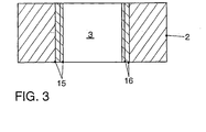
- the large connecting rod 3 and possibly also the small connecting rod 4 are now on measure 16 ( Figure 3). This is done by fine boring or fine spindles. Subsequently, will The connecting rod is subjected to a complete cleaning, measured and classified.
- the inventive production process for a cut connecting rod is substantially the same as above described procedure the same, but it will be the connecting rod eye already after the rooms Side surfaces, the top surfaces and screw supports separated by cutting.
- the dividing surfaces on the connecting rod and the connecting rod cover are cut open individually vacated. This is followed by a washing step, after which the small connecting rod eye is finished and finished.
- the cover screws by inserting Holes and threads introduced into the side surfaces.
- the dividing surfaces on Connecting rod and connecting rod cover are finished, washed again and the Connecting rod cover mounted on the connecting rod.
- the cut surface is restored with a FK laser notched and then the large connecting rod eye is provided with the bearing layer, which is then broken again.
- the connecting rods are washed and the large connecting rod eye is degreased with superheated steam, after which virtually residual moisture is dried freely.
- the connecting rods pretreated in this way are stacked on top of one another 4 to 8, so that the large connecting rod eyes lie concentrically on a corresponding opening of a special pallet.
- the connecting rods are advantageously aligned and fixed over the pre-machined small connecting rod eye and the connecting rod or side surfaces.
- the loaded pallets pass through a supply zone into a sandblasting unit in which the large connecting rod eye is sandblasted to a center roughness R a of approximately 8 to 12 ⁇ m.
- the connecting rods are then moved to a cleaning station and the blasted surface is blown off or blown out with compressed air. Finally, the pretreated connecting rods travel into the plasma station, in which the large connecting rod eye is coated with a rotating plasma torch in a layer thickness 15 of approximately 0.5 mm with an aluminum bronze (FIG. 3). The coated connecting rods then come into a cooling zone, from which the cooled connecting rods are removed from the special pallet and fed to the further processing described above.
- the connecting rods produced according to the invention have the advantage that they are in the large connecting rod No bearing shell included, thus eliminating the bearing shell assembly itself and the Inserting retaining grooves or deburring the bearing shells. This will be the Applying the plasma layer cost competitive. Moreover, at the plasma-coated connecting rods increases assembly safety, since no bearing shells in the Assembly can be omitted.
- the connecting rods according to the invention have a larger web width at the large connecting rod eye Area of bearing cap attachment, since the plasma layer after finishing only about 0.3 mm thick, a bearing shell but 2.5 mm applies. This is a higher Connecting rod load for highly loaded engines and / or weight savings possible. In addition, the gap between two halves of the bearing shell, at which at a higher Burden on the oil film begins to break off.
- the connecting rods according to the invention have thus better lubrication properties.
Description
- Figur 1
- ein Pleuel in Frontansicht;
- Figur 2
- das Pleuel in Seitenansicht; und
- Figur 3
- einen Schichtaufbau in dem großen Pleuelauge.
Claims (19)
- Verfahren zum Herstellen eines Pleuels mit einem Pleuelauge, in dem eine Lagerschicht angeordnet ist, wobei die Lagerschicht durch thermisches Spritzen eines Lagerwerkstoffes direkt auf das Pleuelauge aufgebracht wird, das Pleuelauge vor dem Aufbringen des Lagerwerkstoffes durch Aufschneiden geöffnet wird, das geöffnete Pleuelauge zusammengesetzt wird, das zusammengesetzte Pleuelauge im Bereich der Trennfuge gekerbt wird, danach auf das Pleuelauge der Lagerwerkstoff aufgebracht wird und anschließend das Pleuelauge durch Brechen erneut geöffnet wird.
- Verfahren nach Anspruch 1, dadurch gekennzeichnet, daß der Lagerwerkstoff mittels Plasmaspritzen aufgebracht wird.
- Verfahren nach Anspruch 1 oder 2, dadurch gekennzeichnet, daß als Lagerwerkstoff ein Metall, insbesondere eine Metallegierung und insbesondere ein Gemisch verschiedener Metalle aufgebracht wird.
- Verfahren nach Anspruch 3, dadurch gekennzeichnet, daß als Lagerwerkstoff eine Bronze, insbesondere eine Aluminimumbronze, aufgebracht wird.
- Verfahren nach Anspruch 3 oder 4, dadurch gekennzeichnet, daß als Lagerwerkstoff eine Metall-Weichstoff- und/oder Metall-Festschmierstoff-Schicht aufgebracht wird.
- Verfahren nach einem der vorhergehenden Ansprüche, dadurch gekennzeichnet, daß der aufgebrachte Lagerwerkstoff mechanisch nachbearbeitet wird, insbesondere spannabhebend.
- Verfahren nach Anspruch 6, dadurch gekennzeichnet, daß der aufgebrachte Lagerwerkstoff gehont oder feingespindelt wird.
- Verfahren nach Anspruch 7, dadurch gekennzeichnet, daß beim Honen 20 bis 300 µm, insbesondere 50 bis 200 µm des aufgebrachten Lagerwerkstoffes abgetragen werden.
- Verfahren nach Anspruch 7, dadurch gekennzeichnet, daß beim Feinspindeln 50 bis 1 000 µm, insbesondere 100 bis 500 µm abgetragen werden.
- Verfahren nach einem der vorhergehenden Ansprüche, dadurch gekennzeichnet, daß der Lagerwerkstoff in einer Dicke, ggf. nach einer Nachbearbeitung, von 150 bis 800 µm, insbesondere 200 bis 500 µm hergestellt wird.
- Verfahren nach einem der vorhergehenden Ansprüche, dadurch gekennzeichnet, daß nach dem Aufbringen des Lagerwerkstoffes ein Ölkanal in das Pleuelauge gebohrt wird.
- Verfahren nach einem der vorhergehenden Ansprüche, dadurch gekennzeichnet, daß nach dem Aufbringen des Lagerwerkstoffes die Planflächen des Pleuels nachbearbeitet, insbesondere geschliffen werden.
- Verfahren nach einem der vorhergehenden Ansprüche, dadurch gekennzeichnet, daß vor dem Aufbringen des Lagerwerkstoffes das Pleuelauge aufgerauht wird, insbesondere durch Sandstrahlen.
- Verfahren nach Anspruch 13, dadurch gekennzeichnet, daß das Pleuelauge auf eine Mittenrauhtiefe Ra von 4 bis 30 µm, insbesondere 8 bis 12 µm aufgerauht wird.
- Verfahren nach einem der vorhergehenden Ansprüche, dadurch gekennzeichnet, daß das mit dem Lagerwerkstoff zu beschichtende Pleuelauge und/oder das mit dem Lagerwerkstoff beschichtete Pleuelauge zumindest von einzelnen Pleueln einer Serie zerstörungsfrei vermessen wird.
- Verfahren nach einem der vorhergehenden Ansprüche, dadurch gekennzeichnet, daß der Lagerwerkstoff mittels einer rotierenden Spritzdüse bzw. mittels eines rotierenden Ablenkteils für den Lagerwerkstoffstrahl aufgebracht wird.
- Verfahren nach einem der vorhergehenden Ansprüche, dadurch gekennzeichnet, daß der Lagerwerkstoff in Pulverform aufgespritzt wird.
- Verfahren nach einem der vorhergehenden Ansprüche, dadurch gekennzeichnet, daß während des thermischen Spritzens ein Gasstrom, insbesondere Luftstrom, mit einer Strömungsgeschwindigkeit von 3 bis 15 m/s, insbesondere 5 bis 10 m/s, durch das Pleuelauge geführt wird.
- Verfahren nach einem der vorhergehenden Ansprüche, dadurch gekennzeichnet, daß das thermische Spritzen mit einem Vorschub von 0,5 bis 20 mm/s, insbesondere 2 bis 8 mm/s, durch das Pleuelauge durchgeführt wird.
Applications Claiming Priority (4)
| Application Number | Priority Date | Filing Date | Title |
|---|---|---|---|
| DE19708567 | 1997-03-04 | ||
| DE19708567 | 1997-03-04 | ||
| DE19731625A DE19731625A1 (de) | 1997-03-04 | 1997-07-23 | Lagerwerkstoff in einem Pleuelauge |
| DE19731625 | 1997-07-23 |
Publications (2)
| Publication Number | Publication Date |
|---|---|
| EP0863322A1 EP0863322A1 (de) | 1998-09-09 |
| EP0863322B1 true EP0863322B1 (de) | 2003-11-05 |
Family
ID=26034458
Family Applications (1)
| Application Number | Title | Priority Date | Filing Date |
|---|---|---|---|
| EP98101991A Expired - Lifetime EP0863322B1 (de) | 1997-03-04 | 1998-02-05 | Verfahren zum Herstellen eines Pleuels |
Country Status (3)
| Country | Link |
|---|---|
| EP (1) | EP0863322B1 (de) |
| JP (1) | JPH10311326A (de) |
| CN (1) | CN1129720C (de) |
Cited By (4)
| Publication number | Priority date | Publication date | Assignee | Title |
|---|---|---|---|---|
| DE102004018922A1 (de) * | 2004-04-20 | 2005-11-17 | Bayerische Motoren Werke Ag | Verfahren zur Herstellung eines Bauteils mit einer bruchgetrennten Lageranordnung |
| DE10344723B4 (de) * | 2002-10-04 | 2007-10-11 | Miba Gleitlager Gmbh | Verfahren und Vorrichtung zum Herstellen eines wenigstens ein Lagerauge aufweisenden Werkstückes |
| US7743746B2 (en) | 2004-12-10 | 2010-06-29 | Mahle International Gmbh | Coating for connecting rods and bearings in an internal combustion engine |
| US9291192B2 (en) | 2013-06-17 | 2016-03-22 | Mahle International Gmbh | Connecting rod with bearing-less large end |
Families Citing this family (23)
| Publication number | Priority date | Publication date | Assignee | Title |
|---|---|---|---|---|
| AT405083B (de) * | 1997-04-09 | 1999-05-25 | Avl List Gmbh | Pleuelstange für eine hubkolben-brennkraftmaschine |
| ES2207854T3 (es) | 1997-07-28 | 2004-06-01 | Volkswagen Aktiengesellschaft | Procedimiento de revestimiento termico, especialmente para cojinetes lisos. |
| DE19854462A1 (de) * | 1998-11-25 | 2000-06-15 | Daimler Chrysler Ag | Geteiltes Pleuel, insbesondere für Verbrennungsmaschinen und Verfahren zur Herstellung |
| EP1147239A1 (de) * | 1998-12-18 | 2001-10-24 | Volkswagen Aktiengesellschaft | Verfahren zum thermischen beschichten von flächen eines innenraumes, insbesondere von zylinderlaufflächen eines zylinderkurbelgehäuses einer verbrennungskraftmaschine |
| GB9911171D0 (en) * | 1999-05-13 | 1999-07-14 | United Eng Forgings Ltd | A connecting rod for an internal combustion engine |
| EP1297195A1 (de) * | 2000-05-17 | 2003-04-02 | Saab Ab | Oberflächenbeschichte motorkomponente und herstellungsverfahren dafür |
| AT412168B (de) * | 2002-10-04 | 2004-10-25 | Miba Gleitlager Gmbh | Verfahren zum herstellen eines wenigstens ein lagerauge bildenden werkstückes |
| DE102004026297B4 (de) * | 2004-01-21 | 2007-12-20 | Daimlerchrysler Ag | Geteiltes Lager |
| DE102005037206A1 (de) * | 2005-08-06 | 2007-02-15 | Mahle International Gmbh | Baueinheit für einen Verbrennungsmotor |
| US20070269151A1 (en) * | 2006-05-18 | 2007-11-22 | Hamilton Sundstrand | Lubricated metal bearing material |
| EP1900473A1 (de) * | 2006-09-15 | 2008-03-19 | ThyssenKrupp Automotive AG | Verfahren zur Herstellung eines Pleuels |
| JP4946583B2 (ja) * | 2007-04-12 | 2012-06-06 | マツダ株式会社 | コネクティングロッド |
| DE102010055518A1 (de) | 2010-12-22 | 2012-06-28 | Volkswagen Ag | Lagerbuchse für eine Pleuelstange, Pleuelstange sowie Verfahren zur Herstellung derselben |
| DE102011050662B4 (de) * | 2011-02-10 | 2015-05-28 | Mauser-Werke Oberndorf Maschinenbau Gmbh | Walzwerkzeug |
| DE102011011276A1 (de) | 2011-02-11 | 2012-08-16 | Ferroll Gmbh | Fluidostatische Walzvorrichtung zur Oberflächenbearbeitung und Verfahren zur Randschichtumformung |
| CN102287441A (zh) * | 2011-08-01 | 2011-12-21 | 重庆小康工业集团股份有限公司 | 一种摩托车发动机连杆及其制造工艺 |
| US20130064490A1 (en) * | 2011-09-13 | 2013-03-14 | II Ronald G. Brock | Thermal spray coating of sliding bearing lining layer |
| EP2669399B1 (de) * | 2012-06-01 | 2016-10-12 | Oerlikon Metco AG, Wohlen | Lagerteil, sowie thermisches Spritzverfahren |
| CN102758836B (zh) * | 2012-07-16 | 2014-12-03 | 东风商用车有限公司 | 硬基软结构内燃机连杆 |
| DE102012222327B3 (de) * | 2012-12-05 | 2014-06-05 | Ks Gleitlager Gmbh | Gleitlagerverbundwerkstoff |
| CN104057263B (zh) * | 2014-07-04 | 2017-03-22 | 四川豪特精工装备股份有限公司 | 一种大型机车连杆锻造工艺 |
| CN105041841A (zh) * | 2015-08-12 | 2015-11-11 | 苏州安特实业有限公司 | 一种叉杆零件 |
| CN109099051A (zh) * | 2018-08-09 | 2018-12-28 | 襄阳美标朗源动力实业有限公司 | 一种沼气应用的铝基材质的轴瓦 |
Family Cites Families (7)
| Publication number | Priority date | Publication date | Assignee | Title |
|---|---|---|---|---|
| DE584864C (de) * | 1930-05-24 | 1933-09-25 | Thomas Harry Frost | Feinschneidige duenne Klinge und Verfahren zu ihrer Herstellung |
| GB1083003A (en) * | 1964-10-23 | 1967-09-13 | Glacier Co Ltd | Hot metal spraying of bearing materials |
| US5080056A (en) * | 1991-05-17 | 1992-01-14 | General Motors Corporation | Thermally sprayed aluminum-bronze coatings on aluminum engine bores |
| DE4303592A1 (de) * | 1993-02-08 | 1994-08-11 | Krebsoege Gmbh Sintermetall | Verfahren zum Herstellen eines Bauteils mit wenigstens einem geteilten Lagersitz |
| DE4306280A1 (de) * | 1993-03-01 | 1994-09-08 | Krebsoege Gmbh Sintermetall | Verfahren zum Herstellen eines Bauteils mit wenigstens einer geteilten Lauffläche für Wälzkörper |
| WO1996004485A1 (de) * | 1994-08-01 | 1996-02-15 | Gerold Pankl | Pleuelstange |
| EP0858519B1 (de) * | 1995-10-31 | 2000-05-10 | Volkswagen Aktiengesellschaft | Verfahren zum herstellen einer gleitfläche auf einem metallischen werkstück |
-
1998
- 1998-02-05 EP EP98101991A patent/EP0863322B1/de not_active Expired - Lifetime
- 1998-03-03 JP JP10050925A patent/JPH10311326A/ja active Pending
- 1998-03-04 CN CN98106008A patent/CN1129720C/zh not_active Expired - Fee Related
Cited By (4)
| Publication number | Priority date | Publication date | Assignee | Title |
|---|---|---|---|---|
| DE10344723B4 (de) * | 2002-10-04 | 2007-10-11 | Miba Gleitlager Gmbh | Verfahren und Vorrichtung zum Herstellen eines wenigstens ein Lagerauge aufweisenden Werkstückes |
| DE102004018922A1 (de) * | 2004-04-20 | 2005-11-17 | Bayerische Motoren Werke Ag | Verfahren zur Herstellung eines Bauteils mit einer bruchgetrennten Lageranordnung |
| US7743746B2 (en) | 2004-12-10 | 2010-06-29 | Mahle International Gmbh | Coating for connecting rods and bearings in an internal combustion engine |
| US9291192B2 (en) | 2013-06-17 | 2016-03-22 | Mahle International Gmbh | Connecting rod with bearing-less large end |
Also Published As
| Publication number | Publication date |
|---|---|
| CN1129720C (zh) | 2003-12-03 |
| JPH10311326A (ja) | 1998-11-24 |
| CN1192391A (zh) | 1998-09-09 |
| EP0863322A1 (de) | 1998-09-09 |
Similar Documents
| Publication | Publication Date | Title |
|---|---|---|
| EP0863322B1 (de) | Verfahren zum Herstellen eines Pleuels | |
| DE19731625A1 (de) | Lagerwerkstoff in einem Pleuelauge | |
| DE10230847B3 (de) | Verfahren und Vorrichtung zur Innenbeschichtung von Hohlräumen durch thermisches Spritzen | |
| EP2029317B1 (de) | Verfahren zur herstellung eines pleuels | |
| US3831213A (en) | Composite self-locking fastener | |
| EP1003924B1 (de) | Thermisches beschichtungsverfahren, insbesondere für gleitlager | |
| DE102010014689A1 (de) | Verfahren zum Beschichten einer Oberfläche eines Werkstücks, Motorblock-Rohteil und Motorblock | |
| DE102018202540B4 (de) | Motorblock eines Verbrennungsmotors mit optimierten Wärmeleiteigenschaften | |
| DE102017103442A1 (de) | Extrudierte Zylinderbuchse | |
| DE112015000554T5 (de) | Kolben mit beschichteter Bolzenbohrung | |
| DE19540572A1 (de) | Verfahren zum Herstellen einer Gleitfläche auf einem metallischen Werkstück | |
| EP1000259B1 (de) | Pleuel mit einem mehrlagigen thermisch gespritzten porösen lagerschicht | |
| DE10035032C2 (de) | Verfahren zur Herstellung eines Pleuels | |
| EP1012486B1 (de) | Pleuel mit einer festsitzenden gleitlagerschicht | |
| WO2015192943A1 (de) | Verfahren zum behandeln einer oberfläche | |
| EP1000257B1 (de) | Pleuel mit einem lagermetall | |
| DE102008053641B3 (de) | Thermisch gespritzte Zylinderlaufbahnbeschichtung, Verfahren zu deren Herstellung sowie deren Verwendung in Verbrennungsmotoren | |
| DE10064440B4 (de) | Verfahren und eine Vorrichtung zum Bearbeiten einer Innenfläche einer zylinderförmigen Bohrung eines Bauteils | |
| DE3801784A1 (de) | Leichtmetallkolben fuer brennkraftmaschinen | |
| WO1999005424A1 (de) | Pleuel mit einer dünnen gleitlagerschicht | |
| DE102020211521A1 (de) | Getriebe | |
| DE10306115B4 (de) | Kolben für eine Brennkraftmaschine | |
| EP1225348B1 (de) | Werkstoffverbund-Bauteil mit einer Bruchfläche sowie Verfahren zur Vorbereitung einer Bruchtrennstelle | |
| DE10237923A1 (de) | Lageranordnung und ein zu deren Herstellung bestimmtes Verfahren | |
| EP1173689A1 (de) | Oberflächenlegiertes zylindrisches, teilzylindrisches oder hohlzylindrisches bauteil |
Legal Events
| Date | Code | Title | Description |
|---|---|---|---|
| PUAI | Public reference made under article 153(3) epc to a published international application that has entered the european phase |
Free format text: ORIGINAL CODE: 0009012 |
|
| AK | Designated contracting states |
Kind code of ref document: A1 Designated state(s): DE ES FR GB IT SE |
|
| 17P | Request for examination filed |
Effective date: 19990309 |
|
| AKX | Designation fees paid |
Free format text: DE ES FR GB IT SE |
|
| RBV | Designated contracting states (corrected) |
Designated state(s): DE ES FR GB IT SE |
|
| 17Q | First examination report despatched |
Effective date: 19990811 |
|
| GRAH | Despatch of communication of intention to grant a patent |
Free format text: ORIGINAL CODE: EPIDOS IGRA |
|
| GRAS | Grant fee paid |
Free format text: ORIGINAL CODE: EPIDOSNIGR3 |
|
| GRAA | (expected) grant |
Free format text: ORIGINAL CODE: 0009210 |
|
| AK | Designated contracting states |
Kind code of ref document: B1 Designated state(s): DE ES FR GB IT SE |
|
| PG25 | Lapsed in a contracting state [announced via postgrant information from national office to epo] |
Ref country code: IT Free format text: LAPSE BECAUSE OF FAILURE TO SUBMIT A TRANSLATION OF THE DESCRIPTION OR TO PAY THE FEE WITHIN THE PRESCRIBED TIME-LIMIT;WARNING: LAPSES OF ITALIAN PATENTS WITH EFFECTIVE DATE BEFORE 2007 MAY HAVE OCCURRED AT ANY TIME BEFORE 2007. THE CORRECT EFFECTIVE DATE MAY BE DIFFERENT FROM THE ONE RECORDED. Effective date: 20031105 Ref country code: ES Free format text: LAPSE BECAUSE OF FAILURE TO SUBMIT A TRANSLATION OF THE DESCRIPTION OR TO PAY THE FEE WITHIN THE PRESCRIBED TIME-LIMIT Effective date: 20031105 |
|
| REG | Reference to a national code |
Ref country code: GB Ref legal event code: FG4D Free format text: NOT ENGLISH |
|
| REF | Corresponds to: |
Ref document number: 59810047 Country of ref document: DE Date of ref document: 20031211 Kind code of ref document: P |
|
| PG25 | Lapsed in a contracting state [announced via postgrant information from national office to epo] |
Ref country code: SE Free format text: LAPSE BECAUSE OF FAILURE TO SUBMIT A TRANSLATION OF THE DESCRIPTION OR TO PAY THE FEE WITHIN THE PRESCRIBED TIME-LIMIT Effective date: 20040205 |
|
| GBT | Gb: translation of ep patent filed (gb section 77(6)(a)/1977) |
Effective date: 20040116 |
|
| ET | Fr: translation filed | ||
| PLBE | No opposition filed within time limit |
Free format text: ORIGINAL CODE: 0009261 |
|
| STAA | Information on the status of an ep patent application or granted ep patent |
Free format text: STATUS: NO OPPOSITION FILED WITHIN TIME LIMIT |
|
| 26N | No opposition filed |
Effective date: 20040806 |
|
| PGFP | Annual fee paid to national office [announced via postgrant information from national office to epo] |
Ref country code: DE Payment date: 20140228 Year of fee payment: 17 |
|
| PGFP | Annual fee paid to national office [announced via postgrant information from national office to epo] |
Ref country code: FR Payment date: 20140226 Year of fee payment: 17 |
|
| PGFP | Annual fee paid to national office [announced via postgrant information from national office to epo] |
Ref country code: GB Payment date: 20140228 Year of fee payment: 17 |
|
| REG | Reference to a national code |
Ref country code: DE Ref legal event code: R119 Ref document number: 59810047 Country of ref document: DE |
|
| GBPC | Gb: european patent ceased through non-payment of renewal fee |
Effective date: 20150205 |
|
| REG | Reference to a national code |
Ref country code: FR Ref legal event code: ST Effective date: 20151030 |
|
| PG25 | Lapsed in a contracting state [announced via postgrant information from national office to epo] |
Ref country code: GB Free format text: LAPSE BECAUSE OF NON-PAYMENT OF DUE FEES Effective date: 20150205 Ref country code: DE Free format text: LAPSE BECAUSE OF NON-PAYMENT OF DUE FEES Effective date: 20150901 |
|
| PG25 | Lapsed in a contracting state [announced via postgrant information from national office to epo] |
Ref country code: FR Free format text: LAPSE BECAUSE OF NON-PAYMENT OF DUE FEES Effective date: 20150302 |