EP0863244A2 - Tumble Dryer - Google Patents
Tumble Dryer Download PDFInfo
- Publication number
- EP0863244A2 EP0863244A2 EP98301098A EP98301098A EP0863244A2 EP 0863244 A2 EP0863244 A2 EP 0863244A2 EP 98301098 A EP98301098 A EP 98301098A EP 98301098 A EP98301098 A EP 98301098A EP 0863244 A2 EP0863244 A2 EP 0863244A2
- Authority
- EP
- European Patent Office
- Prior art keywords
- timer
- tumble dryer
- control device
- sensor
- moisture sensor
- Prior art date
- Legal status (The legal status is an assumption and is not a legal conclusion. Google has not performed a legal analysis and makes no representation as to the accuracy of the status listed.)
- Withdrawn
Links
Images


Classifications
-
- D—TEXTILES; PAPER
- D06—TREATMENT OF TEXTILES OR THE LIKE; LAUNDERING; FLEXIBLE MATERIALS NOT OTHERWISE PROVIDED FOR
- D06F—LAUNDERING, DRYING, IRONING, PRESSING OR FOLDING TEXTILE ARTICLES
- D06F58/00—Domestic laundry dryers
- D06F58/30—Drying processes
-
- D—TEXTILES; PAPER
- D06—TREATMENT OF TEXTILES OR THE LIKE; LAUNDERING; FLEXIBLE MATERIALS NOT OTHERWISE PROVIDED FOR
- D06F—LAUNDERING, DRYING, IRONING, PRESSING OR FOLDING TEXTILE ARTICLES
- D06F34/00—Details of control systems for washing machines, washer-dryers or laundry dryers
- D06F34/08—Control circuits or arrangements thereof
-
- D—TEXTILES; PAPER
- D06—TREATMENT OF TEXTILES OR THE LIKE; LAUNDERING; FLEXIBLE MATERIALS NOT OTHERWISE PROVIDED FOR
- D06F—LAUNDERING, DRYING, IRONING, PRESSING OR FOLDING TEXTILE ARTICLES
- D06F2103/00—Parameters monitored or detected for the control of domestic laundry washing machines, washer-dryers or laundry dryers
- D06F2103/02—Characteristics of laundry or load
- D06F2103/04—Quantity, e.g. weight or variation of weight
-
- D—TEXTILES; PAPER
- D06—TREATMENT OF TEXTILES OR THE LIKE; LAUNDERING; FLEXIBLE MATERIALS NOT OTHERWISE PROVIDED FOR
- D06F—LAUNDERING, DRYING, IRONING, PRESSING OR FOLDING TEXTILE ARTICLES
- D06F2103/00—Parameters monitored or detected for the control of domestic laundry washing machines, washer-dryers or laundry dryers
- D06F2103/02—Characteristics of laundry or load
- D06F2103/08—Humidity
- D06F2103/10—Humidity expressed as capacitance or resistance
-
- D—TEXTILES; PAPER
- D06—TREATMENT OF TEXTILES OR THE LIKE; LAUNDERING; FLEXIBLE MATERIALS NOT OTHERWISE PROVIDED FOR
- D06F—LAUNDERING, DRYING, IRONING, PRESSING OR FOLDING TEXTILE ARTICLES
- D06F2103/00—Parameters monitored or detected for the control of domestic laundry washing machines, washer-dryers or laundry dryers
- D06F2103/28—Air properties
- D06F2103/32—Temperature
-
- D—TEXTILES; PAPER
- D06—TREATMENT OF TEXTILES OR THE LIKE; LAUNDERING; FLEXIBLE MATERIALS NOT OTHERWISE PROVIDED FOR
- D06F—LAUNDERING, DRYING, IRONING, PRESSING OR FOLDING TEXTILE ARTICLES
- D06F2103/00—Parameters monitored or detected for the control of domestic laundry washing machines, washer-dryers or laundry dryers
- D06F2103/28—Air properties
- D06F2103/34—Humidity
-
- D—TEXTILES; PAPER
- D06—TREATMENT OF TEXTILES OR THE LIKE; LAUNDERING; FLEXIBLE MATERIALS NOT OTHERWISE PROVIDED FOR
- D06F—LAUNDERING, DRYING, IRONING, PRESSING OR FOLDING TEXTILE ARTICLES
- D06F2103/00—Parameters monitored or detected for the control of domestic laundry washing machines, washer-dryers or laundry dryers
- D06F2103/38—Time, e.g. duration
-
- D—TEXTILES; PAPER
- D06—TREATMENT OF TEXTILES OR THE LIKE; LAUNDERING; FLEXIBLE MATERIALS NOT OTHERWISE PROVIDED FOR
- D06F—LAUNDERING, DRYING, IRONING, PRESSING OR FOLDING TEXTILE ARTICLES
- D06F2105/00—Systems or parameters controlled or affected by the control systems of washing machines, washer-dryers or laundry dryers
- D06F2105/28—Electric heating
-
- D—TEXTILES; PAPER
- D06—TREATMENT OF TEXTILES OR THE LIKE; LAUNDERING; FLEXIBLE MATERIALS NOT OTHERWISE PROVIDED FOR
- D06F—LAUNDERING, DRYING, IRONING, PRESSING OR FOLDING TEXTILE ARTICLES
- D06F2105/00—Systems or parameters controlled or affected by the control systems of washing machines, washer-dryers or laundry dryers
- D06F2105/62—Stopping or disabling machine operation
-
- D—TEXTILES; PAPER
- D06—TREATMENT OF TEXTILES OR THE LIKE; LAUNDERING; FLEXIBLE MATERIALS NOT OTHERWISE PROVIDED FOR
- D06F—LAUNDERING, DRYING, IRONING, PRESSING OR FOLDING TEXTILE ARTICLES
- D06F58/00—Domestic laundry dryers
- D06F58/32—Control of operations performed in domestic laundry dryers
- D06F58/34—Control of operations performed in domestic laundry dryers characterised by the purpose or target of the control
- D06F58/36—Control of operational steps, e.g. for optimisation or improvement of operational steps depending on the condition of the laundry
- D06F58/38—Control of operational steps, e.g. for optimisation or improvement of operational steps depending on the condition of the laundry of drying, e.g. to achieve the target humidity
-
- D—TEXTILES; PAPER
- D06—TREATMENT OF TEXTILES OR THE LIKE; LAUNDERING; FLEXIBLE MATERIALS NOT OTHERWISE PROVIDED FOR
- D06F—LAUNDERING, DRYING, IRONING, PRESSING OR FOLDING TEXTILE ARTICLES
- D06F58/00—Domestic laundry dryers
- D06F58/32—Control of operations performed in domestic laundry dryers
- D06F58/34—Control of operations performed in domestic laundry dryers characterised by the purpose or target of the control
- D06F58/46—Control of the operating time
Definitions
- This invention relates to a tumble dryer for drying wet laundry, and to a control device for such a tumble dryer.
- Known tumble dryers comprise a rotating drum into which articles of clothing to be dried are placed.
- the clothing is dried by blowing hot air across the clothing whilst the drum rotates. Moisture is usually removed in the air exiting the dryer.
- the mechanical movement of the articles in the drum causes the articles to form, at least intermittently, an electrically resistive connection which is in series with a circuit element.
- US patent no. 3765100 discloses a device in which the circuit element is a resistor and the reference potential is selected in relation to the value of the resistor such that a comparator gives an output signal when a given state of dryness of the load has been reached.
- US patent no. 3324568 discloses a control device for a tumble dryer in which the resistance of the load is representative of the state of dryness of the load.
- the device disclosed therein includes means for applying a direct voltage across a series combination of a resistive connection between contact electrodes, and a circuit element in the form of the series combination of a resistor and a neon lamp. When the resistance of the resistive connection is comparatively low use neon lamp ignites and discharges a capacitor.
- European patent no. 0070609 discloses a similar control device for a tumble dryer in which the circuit element is a capacitor and the electrically resistive connection is between a pair of electrodes which are separate from but contactable by the load.
- a control device for a tumble dryer comprising a moisture sensor, and a timer, the timer being triggered by the sensor on sensing a pre-determined trip point, and the timer causing the tumble dryer to switch off at the end of a pre-determined time period after the timer has been triggered.
- an appropriate drying time for any particular load may be determined simply by sensing when a predetermined temperature is achieved within the drum in which the clothes to be dried have been placed and then allowing the drying process to continue for a further pre-determined length of time.
- the inventors have realised that it is possible to select a single predetermined temperature known as a trip temperature which is suitable for substantially all conditions. In other words, they have realised that a single predetermined temperature may be selected which is appropriate for different weights of loads, different composition of loads, different initial moisture levels, different heater settings, etc.
- the time taken to reach the trip temperature is monitored. This data is then used to set the post trip times to dry the load in the tumble dryer. This takes account of varying load sizes, abnormal ambient temperatures, and other odd conditions such as a door being opened etc.
- the process of automatically drying clothes to an appropriate level of dryness is greatly simplified.
- the resulting tumble dryer is also energy efficient in that it does not expend energy over-drying the load.
- the device further comprises a micro-processor containing a number of different algorithms.
- the algorithms select the time from when the trip temperature is reached until the heating is turned off. The time varies dependant upon a number of factors such as weights of loads, composition of loads etc.
- the moisture sensor is a temperature sensor comprising a thermostat sensitive to the temperature of exhaust air exiting from the tumble dryer.
- the moisture sensor comprises a thermistor or thermocouple or humidity or resistance sensor.
- control device controls the heat output of the heater. It may thus be possible for the level of heat to be altered to allow for example the rotatable drum to continue to rotate with either no heat being emitted from the heater, or a lower level of heat. This allows the drying process to end with a cool dry for example.
- a tumble dryer comprising a rotatable drum in which laundry may be dried, a motor for driving the rotating drum, a heater for heating air to dry the clothes within the rotatable drum, and a control device for controlling the drying, the control device comprising a moisture sensor, and a timer, the timer being triggered by the sensor on sensing a predetermined trip point, and the timer causing the tumble dryer to switch off at the end of a predetermined time period after the timer has been triggered.
- a tumble dryer according to a second aspect of the present invention is designated generally by the reference numeral 1.
- the tumble dryer comprises a rotatable drum 6 in which laundry may be dried.
- the rotatable drum is powered by a motor 7.
- the tumble dryer further comprises a heater 8 which heats air within the drum 6 in order to dry laundry within the drum.
- the tumble dryer 1 has an exhaust outlet 4 via which exhaust air is removed from the tumble dryer.
- the tumble dryer 1 comprises a control device 2 according to the first aspect of the present invention.
- the control device comprises a moisture sensing device.
- the moisture sensing device is a temperature sensing device such as a thermostat, thermistor or thermocouple 3 positioned in or close to the exhaust outlet 4 in order that the temperature sensing device is sensitive to the temperature of exhaust air.
- the temperature sensing device is programmed to detect a predetermined temperature of the air exiting through exhaust pipe 4 known as the trip temperature.
- the control device 2 further comprises a microprocessor 9 that controls the length of further time that the tumble dryer will continue to dry the clothes before switching off.
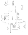
- the control device 2 is designed to operate at 220 volts 60Hz and also 220 / 240 volts and 50Hz.
- the control device may be programmed through two switches shown in Figure 2. Switch 1 (S1) will start the dryer from a momentary pulse. Switch 2 (S2) will control the level of heat.
- the heater may be designed to operate at a number of different levels for example a first level in which full heat is emitted from the heater, and a second level at which less heat is emitted from the heater, for example, half heat output compared to the first setting of the heater and a third level in which no heat is emitted.
- S2 is not present, and a link between pins 15 and 14 will be fitted so that a full heat programme is always selected.
- S2 comprises a single pole on / off switch where, in position 1, the switch is off and there is no signal. This will result in the drying programme running at half heat. In position 2 pin 14 will be contacted, and the drying operation will operate at full heat.
- S2 comprises a 3 position switch. Position 1 contacts pin 13 and results in no heat (cool tumble) in the drying process. Position 2 will result in no signal and drying will take place at half heat. In position 3 pin 14 will be contacted and the drying process will operate at full heat.
- the control device will control both the supply and direction of PSC motor 8.
- the switching of the motor should occur when the motor is in a neutral setting.
- the heater comprises a two element 2500 watt unit.
- the heater may be set at three different levels namely full heat, half heat and no heat by switch S2 as mentioned hereinabove.
- the switch will be mounted on the control panel 5 of the tumble dryer. The control device will therefore power the heater on full, half or no heat settings depending on the position of the heat selection switch S2.
- S2 will not be present. In such circumstances, the control device will operate the heater on full heat at all times.
- Thermostat 3 is mounted in the exhaust of the tumble dryer 1 is used as a sensing system to indicate when the load is almost dry. Once the thermostat has started operating in response to sensing a particular temperature of exhaust air, the control unit begins to decrement a timer. After a predetermined length of time, the heater is switched off and the tumble dryer operates in a cool down setting for a predetermined length of time.
- Switch S2 set to the optional cool tumble position 1, then the dryer will run with the heater off for a preset time. If switch S2 is not present in the dryer, the dryer will run on full heat for a different predetermined time.
- the dryer may have different cycles for example an anti-crease cycle which minimises the need to iron laundry after it has been dried in the dryer.
Abstract
Description
Claims (10)
- A control device for a tumble dryer, the control device comprising a moisture sensor, and a timer, the timer being triggered by the sensor on sensing a predetermined trip point, and the timer causing the tumble dryer to switch off at the end of a predetermined time period after the timer has been triggered.
- A device according to claim 1, further comprising a micro-processor containing a number of different algorithms.
- A device according to claim 1 or claim 2, wherein the moisture sensor is a temperature sensor comprising a thermostat sensitive to the temperature of exhaust air exiting from the tumble dryer.
- A device according to claim 1 or claim 2, wherein the moisture sensor comprises a thermistor.
- A device according to claim 1 or claim 2, wherein the moisture sensor comprises a thermocouple.
- A device according to claim 1 or claim 2, wherein the moisture sensor comprises a humidity sensor.
- A device according to claim 1 or claim 2, wherein the moisture sensor comprises a resistance sensor.
- A device according to any one of the preceding claims, wherein the control device controls the heat output of the heater.
- A tumble dryer comprising a rotatable drum in which laundry may be dried, a motor for driving the rotating drum, a heater for heating air to dry the clothes within the rotatable drum, and a control device for controlling the drying, the control device comprising a moisture sensor and a timer, the timer being triggered by the sensor on sensing a predetermined trip point, and the timer causing the tumble dryer to switch off at the end of the predetermined time period after the timer has been triggered.
- A tumble dryer according to claim 9, comprising a control device according to any one of claims 1 to 8.
Applications Claiming Priority (2)
| Application Number | Priority Date | Filing Date | Title |
|---|---|---|---|
| GBGB9703114.0A GB9703114D0 (en) | 1997-02-14 | 1997-02-14 | Tumble dryer |
| GB9703114 | 1997-02-14 |
Publications (2)
| Publication Number | Publication Date |
|---|---|
| EP0863244A2 true EP0863244A2 (en) | 1998-09-09 |
| EP0863244A3 EP0863244A3 (en) | 1998-10-14 |
Family
ID=10807684
Family Applications (1)
| Application Number | Title | Priority Date | Filing Date |
|---|---|---|---|
| EP98301098A Withdrawn EP0863244A3 (en) | 1997-02-14 | 1998-02-12 | Tumble Dryer |
Country Status (2)
| Country | Link |
|---|---|
| EP (1) | EP0863244A3 (en) |
| GB (1) | GB9703114D0 (en) |
Cited By (6)
| Publication number | Priority date | Publication date | Assignee | Title |
|---|---|---|---|---|
| EP1818441A1 (en) * | 2006-02-14 | 2007-08-15 | Whirlpool Corporation | Drying mode for automatic clothes dryer |
| US8782922B2 (en) | 2010-11-24 | 2014-07-22 | Ecolab Usa Inc. | Dryer monitoring |
| US9080283B2 (en) | 2011-10-06 | 2015-07-14 | Whirlpool Corporation | Method to control a drying cycle of a laundry treating appliance |
| US9206543B2 (en) | 2011-10-14 | 2015-12-08 | Ecolab Usa Inc. | Dryer monitoring |
| US9249539B2 (en) | 2006-09-25 | 2016-02-02 | Ecolab Inc. | Determination of dryness of textiles in a dryer |
| WO2017041712A1 (en) * | 2015-09-09 | 2017-03-16 | 青岛海尔洗衣机有限公司 | Clothes dryer |
Citations (2)
| Publication number | Priority date | Publication date | Assignee | Title |
|---|---|---|---|---|
| US3660909A (en) * | 1970-12-18 | 1972-05-09 | Controls Co Of America | Dryer control |
| US4622759A (en) * | 1984-08-18 | 1986-11-18 | Matsushita Electric Industrial Co., Ltd. | Control system for clothes dryer |
-
1997
- 1997-02-14 GB GBGB9703114.0A patent/GB9703114D0/en active Pending
-
1998
- 1998-02-12 EP EP98301098A patent/EP0863244A3/en not_active Withdrawn
Patent Citations (2)
| Publication number | Priority date | Publication date | Assignee | Title |
|---|---|---|---|---|
| US3660909A (en) * | 1970-12-18 | 1972-05-09 | Controls Co Of America | Dryer control |
| US4622759A (en) * | 1984-08-18 | 1986-11-18 | Matsushita Electric Industrial Co., Ltd. | Control system for clothes dryer |
Cited By (11)
| Publication number | Priority date | Publication date | Assignee | Title |
|---|---|---|---|---|
| EP1818441A1 (en) * | 2006-02-14 | 2007-08-15 | Whirlpool Corporation | Drying mode for automatic clothes dryer |
| US7594343B2 (en) | 2006-02-14 | 2009-09-29 | Whirlpool Corporation | Drying mode for automatic clothes dryer |
| US9249539B2 (en) | 2006-09-25 | 2016-02-02 | Ecolab Inc. | Determination of dryness of textiles in a dryer |
| US8782922B2 (en) | 2010-11-24 | 2014-07-22 | Ecolab Usa Inc. | Dryer monitoring |
| US9080283B2 (en) | 2011-10-06 | 2015-07-14 | Whirlpool Corporation | Method to control a drying cycle of a laundry treating appliance |
| US9206543B2 (en) | 2011-10-14 | 2015-12-08 | Ecolab Usa Inc. | Dryer monitoring |
| US9850621B2 (en) | 2011-10-14 | 2017-12-26 | Ecolab Usa Inc. | Dryer monitoring |
| WO2017041712A1 (en) * | 2015-09-09 | 2017-03-16 | 青岛海尔洗衣机有限公司 | Clothes dryer |
| CN107923117A (en) * | 2015-09-09 | 2018-04-17 | 青岛海尔洗衣机有限公司 | Dryer |
| US10544541B2 (en) | 2015-09-09 | 2020-01-28 | Qingdao Haier Drum Washing Machine Co., Ltd. | Clothes dryer |
| CN107923117B (en) * | 2015-09-09 | 2020-06-30 | 青岛胶南海尔洗衣机有限公司 | Clothes dryer |
Also Published As
| Publication number | Publication date |
|---|---|
| EP0863244A3 (en) | 1998-10-14 |
| GB9703114D0 (en) | 1997-04-02 |
Similar Documents
| Publication | Publication Date | Title |
|---|---|---|
| US5467077A (en) | Method and means for indicating an appliance condition | |
| US4397101A (en) | Automatic dryer control | |
| US3942265A (en) | Dryer control arrangement | |
| KR101276041B1 (en) | apparatus for drying laundary and controlling method of the same | |
| KR910002190B1 (en) | Clothing drying control system | |
| US5651194A (en) | Apparatus and method for controlling reversible dryer | |
| US6446357B2 (en) | Fuzzy logic control for an electric clothes dryer | |
| US4112589A (en) | Control system for drier | |
| US3402478A (en) | Dryer control | |
| CA2185382C (en) | Clothes dryer temperature control system | |
| US3409994A (en) | Heating control system for clothes dryer | |
| US6775924B2 (en) | Heater control system for a clothes dryer | |
| US6757988B2 (en) | Control system for a clothes dryer heater | |
| EP0863244A2 (en) | Tumble Dryer | |
| EP1712672B1 (en) | Combined temperature sensor for clothes dryer | |
| US6819255B2 (en) | Load size detection in a fabric dryer | |
| CA2364067C (en) | Cool down temperature control system for clothes dryer | |
| US3436838A (en) | Dryer control | |
| GB1572811A (en) | Fan blown hot air tumble driers | |
| US3398461A (en) | Dryer with antiwrinkle cycle | |
| US4112588A (en) | Drier appliance control | |
| US3714717A (en) | Knit cycle for clothes dryer | |
| JP3322000B2 (en) | Clothes dryer | |
| JPS5971787A (en) | Clothing dryer | |
| JP3958696B2 (en) | Clothes dryer |
Legal Events
| Date | Code | Title | Description |
|---|---|---|---|
| PUAI | Public reference made under article 153(3) epc to a published international application that has entered the european phase |
Free format text: ORIGINAL CODE: 0009012 |
|
| PUAL | Search report despatched |
Free format text: ORIGINAL CODE: 0009013 |
|
| AK | Designated contracting states |
Kind code of ref document: A2 Designated state(s): AT BE CH DE DK ES FI FR GB GR IE IT LI LU MC NL PT SE |
|
| AX | Request for extension of the european patent |
Free format text: AL;LT;LV;MK;RO;SI |
|
| AK | Designated contracting states |
Kind code of ref document: A3 Designated state(s): AT BE CH DE DK ES FI FR GB GR IE IT LI LU MC NL PT SE |
|
| AX | Request for extension of the european patent |
Free format text: AL;LT;LV;MK;RO;SI |
|
| AKX | Designation fees paid | ||
| STAA | Information on the status of an ep patent application or granted ep patent |
Free format text: STATUS: THE APPLICATION IS DEEMED TO BE WITHDRAWN |
|
| 18D | Application deemed to be withdrawn |
Effective date: 19990415 |
|
| REG | Reference to a national code |
Ref country code: DE Ref legal event code: 8566 |