EP0862399B1 - A device having rotatable legs - Google Patents
A device having rotatable legs Download PDFInfo
- Publication number
- EP0862399B1 EP0862399B1 EP97937218A EP97937218A EP0862399B1 EP 0862399 B1 EP0862399 B1 EP 0862399B1 EP 97937218 A EP97937218 A EP 97937218A EP 97937218 A EP97937218 A EP 97937218A EP 0862399 B1 EP0862399 B1 EP 0862399B1
- Authority
- EP
- European Patent Office
- Prior art keywords
- hearing
- protection device
- leg
- band
- hole
- Prior art date
- Legal status (The legal status is an assumption and is not a legal conclusion. Google has not performed a legal analysis and makes no representation as to the accuracy of the status listed.)
- Expired - Lifetime
Links
Images




Classifications
-
- H—ELECTRICITY
- H04—ELECTRIC COMMUNICATION TECHNIQUE
- H04R—LOUDSPEAKERS, MICROPHONES, GRAMOPHONE PICK-UPS OR LIKE ACOUSTIC ELECTROMECHANICAL TRANSDUCERS; ELECTRIC HEARING AIDS; PUBLIC ADDRESS SYSTEMS
- H04R5/00—Stereophonic arrangements
- H04R5/033—Headphones for stereophonic communication
- H04R5/0335—Earpiece support, e.g. headbands or neckrests
-
- A—HUMAN NECESSITIES
- A61—MEDICAL OR VETERINARY SCIENCE; HYGIENE
- A61F—FILTERS IMPLANTABLE INTO BLOOD VESSELS; PROSTHESES; DEVICES PROVIDING PATENCY TO, OR PREVENTING COLLAPSING OF, TUBULAR STRUCTURES OF THE BODY, e.g. STENTS; ORTHOPAEDIC, NURSING OR CONTRACEPTIVE DEVICES; FOMENTATION; TREATMENT OR PROTECTION OF EYES OR EARS; BANDAGES, DRESSINGS OR ABSORBENT PADS; FIRST-AID KITS
- A61F11/00—Methods or devices for treatment of the ears or hearing sense; Non-electric hearing aids; Methods or devices for enabling ear patients to achieve auditory perception through physiological senses other than hearing sense; Protective devices for the ears, carried on the body or in the hand
- A61F11/06—Protective devices for the ears
- A61F11/08—Protective devices for the ears internal, e.g. earplugs
- A61F11/12—External mounting means
-
- H—ELECTRICITY
- H04—ELECTRIC COMMUNICATION TECHNIQUE
- H04R—LOUDSPEAKERS, MICROPHONES, GRAMOPHONE PICK-UPS OR LIKE ACOUSTIC ELECTROMECHANICAL TRANSDUCERS; ELECTRIC HEARING AIDS; PUBLIC ADDRESS SYSTEMS
- H04R1/00—Details of transducers, loudspeakers or microphones
- H04R1/10—Earpieces; Attachments therefor ; Earphones; Monophonic headphones
- H04R1/1016—Earpieces of the intra-aural type
-
- H—ELECTRICITY
- H04—ELECTRIC COMMUNICATION TECHNIQUE
- H04R—LOUDSPEAKERS, MICROPHONES, GRAMOPHONE PICK-UPS OR LIKE ACOUSTIC ELECTROMECHANICAL TRANSDUCERS; ELECTRIC HEARING AIDS; PUBLIC ADDRESS SYSTEMS
- H04R1/00—Details of transducers, loudspeakers or microphones
- H04R1/10—Earpieces; Attachments therefor ; Earphones; Monophonic headphones
- H04R1/1058—Manufacture or assembly
- H04R1/1066—Constructional aspects of the interconnection between earpiece and earpiece support
Definitions
- the invention relates generally to hearing protection devices and in particular to a hearing protection device including rotatable legs for adjusting the position of hearing protectors.
- JP-A-06351090 and JP-A-59210790 describe foldable headphone units.
- Hearing protectors fall generally into three categories, including protectors that cap the entrance to the ear canal; protectors which enter the ear canal and seal the ear canal prior to the bend in the ear canal (usually referred to simply as semi-insert devices); and protectors that enter the ear canal and take the bend in the ear canal (sometimes referred to as banded earplugs).
- US, 4,671,265 describes an earplug device including a headband with earplugs attached to the ends thereof.
- US 2 420 245 discloses an ear muff having swivel joints permitting links holding the muffs to move inwardly and outwardly.
- Semi-insert hearing protectors generally protect similarly to earplugs, but usually to a lesser level.
- Semi-insert hearing protectors are also referred to as semi-aural hearing protectors. Semi-insert hearing protectors which enter the ear canal to a greater degree offer better protection but are somewhat less comfortable than those which simply cap the ear. Products which cap the ear have some of the attributes of both earplugs and earmuffs. Typically, they are used for intermittent noise exposures where lighter weight and improved low frequency attenuation are desirable. As used herein, "hearing protectors” refers generally to hearing protectors falling into one of the three categories described above.
- FIGURE 12 is a front view of a conventional hearing protection device disclosed in U.S. Patent 4,461,290.
- the hearing protection device includes a U-shaped headband 1 having affixed to each of the opposed end portions 3 and 5 an inwardly directed ear obturating pod 2.
- a pair of balls 7 and 9 engage a socket formed in the pods 2 and attach the pods 2 to the headband 1.
- the conventional headband 1 may have certain drawbacks and deficiencies.
- the shape of the headband is such that when the pods 2 are mounted in the wearer's ears, portions of the headband 1 are close to or touching the wearer's head. This can be irritating and uncomfortable to the wearer.
- the hearing protection device includes a frame having a band and a pair of legs.
- the pair of legs are rotatably coupled to the ends of the band.
- Each leg has a first leg end rotatably coupled to a respective band end and a second leg end for receiving a hearing protector.
- each second end has a mating means (preferably an opening) for receiving a stem portion of the hearing protector.
- the hearing protector in accordance with this invention provides several important features and advantages relative to the prior art.
- the rotatable legs allow the band to accommodate virtually any head size and provide the wearer with both comfort and a variety of wearing positions.
- FIGURE 1 is a front view of the frame of the hearing protection device in a first embodiment of the invention.
- the frame is shown generally at 10.
- the frame 10 includes a band 12 and a pair of legs shown generally at 14.
- the band 12 is generally U-shaped and is made from a resilient, flexible material such as plastic.
- the band 12 has two leg supports 16, each of which forms one half of a swivel or rotating joint between the band 12 and the leg 14.
- the leg support 16 is integral with the band 12 and in an exemplary embodiment is a spherical segment.
- the leg 14 includes a first leg end 18 which is integral with leg 14 and, in an exemplary embodiment, is a spherical segment.
- the flat faces of the first leg end 18 and the leg support 16 are placed opposite each other to form a swivel joint.
- the details of the swivel joint are described below with reference to FIGURES 6 and 7.
- the swivel joint allows the first leg end 18 to rotate relative to the leg support 16 thereby allowing the leg 14 to rotate relative to the band 12.
- the band 12 lies substantially in a plane and as the legs 14 are rotated, a plurality of angles are defined between the leg 14 and the plane. It is understood that the band 12 and leg supports 16 need not lie in the same plane as shown in FIGURE 4.
- the leg supports 16 may lie in a plane different than the band 12 and each leg 14 will rotate through a plurality of angles between the leg 14 and the plane of the leg supports 16.
- the leg 14 includes a second leg end 20 for receiving a hearing protector 100 (shown in FIGURES 11A and 11B).
- the second leg end 20 is a spherical segment. It will be appreciated that second leg end 20 may comprise any other desired functional shape such as ovular, triangular, etc.
- FIGURES 2-5 are various views of the frame of the hearing protection device of FIGURE 1 and are self-explanatory.
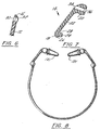
- FIGURE 6 is a cross-sectional view of the leg support 16 and FIGURE 7 is a cross-sectional view of the leg 14.
- the leg 14 includes first leg end 18, second leg end 20 and leg body 22.
- the first leg end 18 has a planar surface 28 and a post 24 substantially perpendicular to the planar surface 28.
- the post 24 has a neck region 26 where the diameter of the post 24 is smaller than the diameter of the end of the post 24 away from the planar surface 28.
- the leg support 16 includes a hole 32 formed therethrough for receiving the post 24.
- the neck 26 snap-lockedly engages a ridge 30 formed in the hole 32.
- the ridge 30 has an inner diameter that is smaller than the inner diameter of the hole 32. That is, the ridge 30 extends away from the inner wall of the hole 32.
- the interference fit between the neck 26 and the ridge 30 holds the leg 14 to the band 12 while allowing the post 24 to rotate within the hole 32. Because the band 12 and the leg 14 are made from a resilient material, such as plastic, the interference fit between the neck 26 and the ridge 30 can be defeated by pulling the post 24 out of the hole 32 if necessary.
- the planar surface 28 of the first leg end 18 is at an oblique angle relative to the major axis of the leg body 22. This causes the leg 14 to be angled towards the interior of the U-shaped band 12 as shown in FIGURE 1. This results in the second leg ends 20, which hold the hearing protectors as shown in FIGURES 8-10, being close to the wearer's head and the band 12 being away from the wearer's head. Because the band 12 is positioned away from the wearer's head, it is less likely that the band 12 will contact and irritate the wearer. Thus, the comfort of the hearing protection device is improved over the prior art.
- the tension on the band 12 can remain approximately the same for varying head sizes.
- the only way to adjust the distance between the hearing protectors 2 is to flex the band 1. This results in increasing tension as the wearer's head size increases.
- the frame 10 shown in FIGURE 1 allows the distance between the hearing protectors to be adjusted without flexing the band 12.
- wearers with different head sizes can achieve approximately the same tension in the band 12.
- the frame 10 can comfortably accommodate head sizes ranging from, for example, the 5th percentile of women to the 95th percentile of men.
- the legs 14 may be rotated while the hearing protection device is being worn to allow modification of the fit without removing the hearing protection device.
- the hearing protection device can be worn with the band 12 under the chin (as shown in FIGURE 13A), over the top of the head (as shown in FIGURE 13B), or behind the back of the head based on the wearer's preference (as shown in FIGURE 13C).
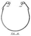
- the second leg end 20 includes a hole 34 formed therein for receiving various hearing protectors 101-103 as shown in FIGURES 8-10.
- the hearing protectors may be protectors that cap the entrance to the ear canal; protectors which enter the ear canal and seal the ear canal prior to the bend in the ear canal; or protectors that enter the ear canal and take the bend in the ear canal.
- FIGURES 14A-14C illustrate additional hearing protectors 110-112 that may be mounted to the second leg end 20.
- FIGURE 15 is a cross-sectional view of a hearing protector 113 that may be mounted to the second leg end 20. The hearing protector 113 attenuates sound over a wide frequency range uniformly. Additional details of the hearing protector in FIGURE 15 are provided in U.S. Patent 5,113,967.
- the hearing protection device of the present invention provides a comfortable fit regardless of the size or shape of the hearing protectors mounted in the second leg ends 20.
- a hearing protector 100 comprises a foam portion 106 coupled to a stem 104.
- the hearing protector in FIGURE 11A is a conventional hearing protector in which the foam portion 106 is glued to the stem 104.
- the hearing protector shown in FIGURE 11B is an improved design in which the stem 104 is made from a porous material and the foam 106 interpenetrates the pores in the stem 104 to form a mechanical bond. This hearing protector shown in FIGURE 11B is described in additional detail below.
- the foam portion 106 is a dynamically stiff foam.
- a suitable dynamically stiff foam is described in commonly assigned U.S. Patent 5,420,381.
- the foam portion 106 may comprise any other conventional earplug foam material such as the foam disclosed in U.S. Reissue Patent 29,487.
- the stem 104 is placed in the hole 34.
- Hole 34 includes a tapered area 36 (shown in FIGURE 7) that eases placement of the hearing protector 100 in hole 34.
- the stem 104 is preferably flexible so that it flexes as the wearer moves their head. A non-pliable stem may cause discomfort as the wearer moves their head. By using a flexible stem 104, an extra degree of freedom is introduced into the hearing protection device.
- the foam portion 106 moves along with the wearer's head and provides additional comfort.
- the stem 104 should be made from a compressible, resilient material and have a diameter slightly larger than the diameter of hole 34. When the stem 104 is positioned in hole 34, the stem 104 will press against the wall of hole 34 and provide a friction fit.
- the hole 34 need not be formed completely through the second leg end 20 for the stem 104 to be securely mounted to the second leg end 20. However, if the hole 34 is formed all the way through the second leg end 20, the stem 104 can be pushed out of the second leg end 20 to aid removal of the hearing protector 100 if necessary.
- the stem 104 is made from a porous material, such as that disclosed in the U.S. Patent 5,799,658 filed contemporaneously herewith entitled "Hearing Protective Device Comprising a Foam and a Porous Component, and Method of Manufacturing Thereof".
- the porous material is both flexible and compressible.
- the porous material is preferably a polymer or combination of polymers in the form of small particles of one or more size ranges bonded in such a way as to leave voids or pores within the material.
- the pores may be of varying sizes.
- the pore volume is in the range from about ten percent to about ninety percent of the total volume, with the most preferred pore volume being in the range from about thirty to about sixty percent of the total volume.
- a particularly preferred porous component is Swab-002 made from INTERFLO®, available from Interflo Technologies, Brooklyn, NY.
- the foam 106 interpenetrates the pores in the porous stem 104 to mechanically bond the foam portion 106 to the stem 104.
- an ear protective device may be mounted to the ends of legs 14 in any suitable manner in addition to the hole 34 with mating stem 104 approach shown in the preferred embodiments.
- a foam or other earplug device could be attached using a ball and socket configuration as in prior art FIGURE 12, or any other approach may be used whereby the earplug is attached to leg 14.
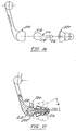
- FIGURE 16 is an exploded view of an alternative system for mounting a hearing protector to the frame.
- a shaft 210 includes a first ball 212 and a second ball 216 joined by a shaft neck 218.
- the first ball 212 engages a socket 202 (shown in FIGURE 17) formed in the frame end 200.
- the socket 202 may be formed in the second leg end 20 shown in FIGURE 1.
- the second ball 216 engages a hearing protector 220.
- the hearing protector 220 shown in FIGURE 16 is a multiple flange earplug similar to the earplug described in U.S. Patent 4,867,149. It is understood, however, that any hearing protector may be configured for use with shaft 210.
- FIGURE 17 is a partial cross sectional view of the hearing protector 220 mounted to the frame end 200 through shaft 210.
- the first ball 212 is placed within socket 202.
- the socket 202 includes a lip 204 that extends into the socket 202 to reduce the diameter of the opening of the socket 202.
- the outer diameter of the first ball 212 is slightly smaller than the inner diameter of the socket 202.
- the frame end 200 is made from a resilient material (e.g., plastic) and the lip 204 flexes to allow the first ball 212 to be placed within the socket 202.
- the lip 204 then returns to its original position once the first ball 212 is placed in the socket 202.
- the interference fit between the lip 204 and the first ball 212 retains the shaft 210 in the frame end 200.
- either the second leg end 20 or the reverse curve end 20' may include the socket 202 and lip 204.
- the hearing protector 220 is then placed on the shaft 210 and retained on the shaft by the interference fit between the second ball
- FIGURES 16 and 17 allow the hearing protector 220 to rotate way from a center line of the socket 202 by an angle ⁇ .
- FIGURE 17 illustrates the hearing protector 220 in three different positions. In an exemplary embodiment, a equals 27°.
- the use of the ball and socket mounting system shown in FIGURES 16 and 17 introduces additional degrees of freedom in the hearing protection device. This allows the wearer to finely adjust the position of the hearing protectors for a more comfortable fit.
- the present invention provides a hearing protection device that comfortably fits head sizes ranging from the 5th percentile of women to the 95th percentile of men. This is accomplished through legs having a first end rotatably coupled to a band and a second end for receiving hearing protectors. As the legs are rotated, the distance between the hearing protectors varies. This allows wearers with differing head sizes to achieve the substantially the same band tension. To increase comfort, the hearing protector may be mounted on a flexible stem which allows the hearing protector to move relative to the leg. Alternatively, a ball and socket mounting system may be used to allow the wearer to finely adjust the position of the hearing protectors relative to the frame.
Landscapes
- Health & Medical Sciences (AREA)
- Engineering & Computer Science (AREA)
- Life Sciences & Earth Sciences (AREA)
- Acoustics & Sound (AREA)
- Physics & Mathematics (AREA)
- Vascular Medicine (AREA)
- General Health & Medical Sciences (AREA)
- Otolaryngology (AREA)
- Biomedical Technology (AREA)
- Heart & Thoracic Surgery (AREA)
- Biophysics (AREA)
- Animal Behavior & Ethology (AREA)
- Psychology (AREA)
- Public Health (AREA)
- Veterinary Medicine (AREA)
- Signal Processing (AREA)
- Headphones And Earphones (AREA)
- Orthopedics, Nursing, And Contraception (AREA)
- Professional, Industrial, Or Sporting Protective Garments (AREA)
- Casings For Electric Apparatus (AREA)
- Measurement Of The Respiration, Hearing Ability, Form, And Blood Characteristics Of Living Organisms (AREA)
Description
- The invention relates generally to hearing protection devices and in particular to a hearing protection device including rotatable legs for adjusting the position of hearing protectors.
- JP-A-06351090 and JP-A-59210790 describe foldable headphone units.
- Hearing protectors fall generally into three categories, including protectors that cap the entrance to the ear canal; protectors which enter the ear canal and seal the ear canal prior to the bend in the ear canal (usually referred to simply as semi-insert devices); and protectors that enter the ear canal and take the bend in the ear canal (sometimes referred to as banded earplugs). US, 4,671,265 describes an earplug device including a headband with earplugs attached to the ends thereof. US 2 420 245 discloses an ear muff having swivel joints permitting links holding the muffs to move inwardly and outwardly. Semi-insert hearing protectors generally protect similarly to earplugs, but usually to a lesser level. Semi-insert hearing protectors are also referred to as semi-aural hearing protectors. Semi-insert hearing protectors which enter the ear canal to a greater degree offer better protection but are somewhat less comfortable than those which simply cap the ear. Products which cap the ear have some of the attributes of both earplugs and earmuffs. Typically, they are used for intermittent noise exposures where lighter weight and improved low frequency attenuation are desirable. As used herein, "hearing protectors" refers generally to hearing protectors falling into one of the three categories described above.
- FIGURE 12 is a front view of a conventional hearing protection device disclosed in U.S. Patent 4,461,290. The hearing protection device includes a U-shaped headband 1 having affixed to each of the
opposed end portions 3 and 5 an inwardly directed ear obturating pod 2. A pair of balls 7 and 9 engage a socket formed in the pods 2 and attach the pods 2 to the headband 1. While well-suited for its intended purposes, the conventional headband 1 may have certain drawbacks and deficiencies. For example, the shape of the headband is such that when the pods 2 are mounted in the wearer's ears, portions of the headband 1 are close to or touching the wearer's head. This can be irritating and uncomfortable to the wearer. In addition, there is no mechanism for adjusting the headband to allow for varying head sizes. A wearer with a large head requires a large distance between theheadband ends 3 and 5. Unfortunately, as the distance between the headband ends 3 and 5 increases, so does the tension in the headband 1. Accordingly, wearers with large heads may experience discomfort due to this high tension in the headband 1. In order to accommodate varying head sizes, the headband 1 must be manufactured in multiple sizes which increases manufacturing costs. Accordingly, there is a perceived need in the art for a hearing protection device that can comfortably fit a wide variety of head sizes. - The above-discussed and other drawbacks and deficiencies of the prior art are overcome or alleviated in accordance with the present invention by the hearing protection device as claimed in claim 1. In a preferred embodiment at least, the hearing protection device includes a frame having a band and a pair of legs. The pair of legs are rotatably coupled to the ends of the band. Each leg has a first leg end rotatably coupled to a respective band end and a second leg end for receiving a hearing protector. In a preferred embodiment, each second end has a mating means (preferably an opening) for receiving a stem portion of the hearing protector.
- The hearing protector in accordance with this invention provides several important features and advantages relative to the prior art. For example, the rotatable legs allow the band to accommodate virtually any head size and provide the wearer with both comfort and a variety of wearing positions.
- The above-discussed features and advantages of the present invention will be appreciated and understood by those skilled in the art from the following description and drawings.
- Referring now to the drawings wherein like elements are numbered alike in the several FIGURES:
- FIGURE 1 is a front view of a frame of a hearing protection device in a first embodiment of the invention;
- FIGURE 2 is a top view of the frame of FIGURE 1;
- FIGURE 3 is a bottom view of the frame of FIGURE 1;
- FIGURE 4 is a side view of the frame of FIGURE 1;
- FIGURE 5 is a view taken along line 5-5 in FIGURE 1;
- FIGURE 6 is a cross-sectional view of one end of a band shown in FIGURE 1;
- FIGURE 7 is a cross-sectional view of a leg shown in FIGURE 1;
- FIGURE 8 is a front view of the frame of FIGURE 1 fitted with a first type hearing protector;
- FIGURE 9 is a front view of the frame of FIGURE 1 fitted with a second type of hearing protector;
- FIGURE 10 is a front view of the frame of FIGURE 1 fitted with a third type of hearing protector;
- FIGURES 11A-11B are a cross-sectional views of a hearing protectors for use with the hearing protection device of FIGURE 1;
- FIGURE 12 is a front view of a conventional hearing protection device;
- FIGURES 13A-C are perspective views depicting the hearing protective device of this invention in three different positions on a wearer's head;
- FIGURES 14A-14C are front views of the frame fitted with a variety of hearing protectors;
- FIGURE 15 is a cross-sectional view of a frequency attenuating hearing protector for use with the present invention;
- FIGURE 16 is an exploded view of an alternative system for mounting a hearing protector to the frame;
- FIGURE 17 is a partial cross-sectional view of a hearing protector mounted to the frame using the system of FIGURE 16.
- FIGURE 1 is a front view of the frame of the hearing protection device in a first embodiment of the invention. The frame is shown generally at 10. The frame 10 includes a
band 12 and a pair of legs shown generally at 14. Theband 12 is generally U-shaped and is made from a resilient, flexible material such as plastic. Theband 12 has two leg supports 16, each of which forms one half of a swivel or rotating joint between theband 12 and theleg 14. Theleg support 16 is integral with theband 12 and in an exemplary embodiment is a spherical segment. Theleg 14 includes afirst leg end 18 which is integral withleg 14 and, in an exemplary embodiment, is a spherical segment. The flat faces of thefirst leg end 18 and theleg support 16 are placed opposite each other to form a swivel joint. The details of the swivel joint are described below with reference to FIGURES 6 and 7. The swivel joint allows thefirst leg end 18 to rotate relative to theleg support 16 thereby allowing theleg 14 to rotate relative to theband 12. Theband 12 lies substantially in a plane and as thelegs 14 are rotated, a plurality of angles are defined between theleg 14 and the plane. It is understood that theband 12 and leg supports 16 need not lie in the same plane as shown in FIGURE 4. Indeed, as shown in FIGURES 13 A, B and C (and discussed hereafter) the leg supports 16 may lie in a plane different than theband 12 and eachleg 14 will rotate through a plurality of angles between theleg 14 and the plane of the leg supports 16. Theleg 14 includes asecond leg end 20 for receiving a hearing protector 100 (shown in FIGURES 11A and 11B). In an exemplary embodiment, thesecond leg end 20 is a spherical segment. It will be appreciated thatsecond leg end 20 may comprise any other desired functional shape such as ovular, triangular, etc. The outer dimension of thesecond leg end 20 is preferably equal to the average concha bowl opening so that thesecond leg end 20 cannot be inserted into the ear canal but is preferably insertable (and rests in) the concha bowl (so that the earplug attached to end 20 is permitted to freely articulate in the ear canal). FIGURES 2-5 are various views of the frame of the hearing protection device of FIGURE 1 and are self-explanatory. - FIGURE 6 is a cross-sectional view of the
leg support 16 and FIGURE 7 is a cross-sectional view of theleg 14. Theleg 14 includesfirst leg end 18,second leg end 20 and leg body 22. Thefirst leg end 18 has aplanar surface 28 and a post 24 substantially perpendicular to theplanar surface 28. The post 24 has aneck region 26 where the diameter of the post 24 is smaller than the diameter of the end of the post 24 away from theplanar surface 28. Theleg support 16 includes ahole 32 formed therethrough for receiving the post 24. Theneck 26 snap-lockedly engages aridge 30 formed in thehole 32. Theridge 30 has an inner diameter that is smaller than the inner diameter of thehole 32. That is, theridge 30 extends away from the inner wall of thehole 32. The interference fit between theneck 26 and theridge 30 holds theleg 14 to theband 12 while allowing the post 24 to rotate within thehole 32. Because theband 12 and theleg 14 are made from a resilient material, such as plastic, the interference fit between theneck 26 and theridge 30 can be defeated by pulling the post 24 out of thehole 32 if necessary. - The
planar surface 28 of thefirst leg end 18 is at an oblique angle relative to the major axis of the leg body 22. This causes theleg 14 to be angled towards the interior of theU-shaped band 12 as shown in FIGURE 1. This results in the second leg ends 20, which hold the hearing protectors as shown in FIGURES 8-10, being close to the wearer's head and theband 12 being away from the wearer's head. Because theband 12 is positioned away from the wearer's head, it is less likely that theband 12 will contact and irritate the wearer. Thus, the comfort of the hearing protection device is improved over the prior art. - In addition, as the
legs 14 are rotated, the distance between the second leg ends 20 varies. Therefore, the tension on theband 12 can remain approximately the same for varying head sizes. In the device shown in FIGURE 12, the only way to adjust the distance between the hearing protectors 2 is to flex the band 1. This results in increasing tension as the wearer's head size increases. The frame 10 shown in FIGURE 1 allows the distance between the hearing protectors to be adjusted without flexing theband 12. Thus, wearers with different head sizes can achieve approximately the same tension in theband 12. In this way, the frame 10 can comfortably accommodate head sizes ranging from, for example, the 5th percentile of women to the 95th percentile of men. Thelegs 14 may be rotated while the hearing protection device is being worn to allow modification of the fit without removing the hearing protection device. In addition, the hearing protection device can be worn with theband 12 under the chin (as shown in FIGURE 13A), over the top of the head (as shown in FIGURE 13B), or behind the back of the head based on the wearer's preference (as shown in FIGURE 13C). - The
second leg end 20 includes ahole 34 formed therein for receiving various hearing protectors 101-103 as shown in FIGURES 8-10. As mentioned above, the hearing protectors may be protectors that cap the entrance to the ear canal; protectors which enter the ear canal and seal the ear canal prior to the bend in the ear canal; or protectors that enter the ear canal and take the bend in the ear canal. FIGURES 14A-14C illustrate additional hearing protectors 110-112 that may be mounted to thesecond leg end 20. FIGURE 15 is a cross-sectional view of ahearing protector 113 that may be mounted to thesecond leg end 20. Thehearing protector 113 attenuates sound over a wide frequency range uniformly. Additional details of the hearing protector in FIGURE 15 are provided in U.S. Patent 5,113,967. - The hearing protection device of the present invention provides a comfortable fit regardless of the size or shape of the hearing protectors mounted in the second leg ends 20.
- As shown in FIGURES 11A and 11B, a
hearing protector 100 comprises afoam portion 106 coupled to astem 104. The hearing protector in FIGURE 11A is a conventional hearing protector in which thefoam portion 106 is glued to thestem 104. The hearing protector shown in FIGURE 11B is an improved design in which thestem 104 is made from a porous material and thefoam 106 interpenetrates the pores in thestem 104 to form a mechanical bond. This hearing protector shown in FIGURE 11B is described in additional detail below. - In an exemplary embodiment, the
foam portion 106 is a dynamically stiff foam. A suitable dynamically stiff foam is described in commonly assigned U.S. Patent 5,420,381. Alternatively, thefoam portion 106 may comprise any other conventional earplug foam material such as the foam disclosed in U.S. Reissue Patent 29,487. - The
stem 104 is placed in thehole 34. The use ofhole 34 and stem mounted hearingprotector 100 allows the wearer to change hearing protectors easily.Hole 34 includes a tapered area 36 (shown in FIGURE 7) that eases placement of thehearing protector 100 inhole 34. Thestem 104 is preferably flexible so that it flexes as the wearer moves their head. A non-pliable stem may cause discomfort as the wearer moves their head. By using aflexible stem 104, an extra degree of freedom is introduced into the hearing protection device. Thefoam portion 106 moves along with the wearer's head and provides additional comfort. - To provide a tight fit in the
hole 34, thestem 104 should be made from a compressible, resilient material and have a diameter slightly larger than the diameter ofhole 34. When thestem 104 is positioned inhole 34, thestem 104 will press against the wall ofhole 34 and provide a friction fit. Thehole 34 need not be formed completely through thesecond leg end 20 for thestem 104 to be securely mounted to thesecond leg end 20. However, if thehole 34 is formed all the way through thesecond leg end 20, thestem 104 can be pushed out of thesecond leg end 20 to aid removal of thehearing protector 100 if necessary. - As previously mentioned with reference to FIGURE 11B, in an exemplary embodiment, the
stem 104 is made from a porous material, such as that disclosed in the U.S. Patent 5,799,658 filed contemporaneously herewith entitled "Hearing Protective Device Comprising a Foam and a Porous Component, and Method of Manufacturing Thereof". The porous material is both flexible and compressible. The porous material is preferably a polymer or combination of polymers in the form of small particles of one or more size ranges bonded in such a way as to leave voids or pores within the material. The pores may be of varying sizes. Preferably, the pore volume is in the range from about ten percent to about ninety percent of the total volume, with the most preferred pore volume being in the range from about thirty to about sixty percent of the total volume. A particularly preferred porous component is Swab-002 made from INTERFLO®, available from Interflo Technologies, Brooklyn, NY. Thefoam 106 interpenetrates the pores in theporous stem 104 to mechanically bond thefoam portion 106 to thestem 104. - It will be appreciated that an ear protective device may be mounted to the ends of
legs 14 in any suitable manner in addition to thehole 34 withmating stem 104 approach shown in the preferred embodiments. For example, a foam or other earplug device could be attached using a ball and socket configuration as in prior art FIGURE 12, or any other approach may be used whereby the earplug is attached toleg 14. - FIGURE 16 is an exploded view of an alternative system for mounting a hearing protector to the frame. A
shaft 210 includes afirst ball 212 and asecond ball 216 joined by ashaft neck 218. Thefirst ball 212 engages a socket 202 (shown in FIGURE 17) formed in theframe end 200. Thesocket 202 may be formed in thesecond leg end 20 shown in FIGURE 1. Thesecond ball 216 engages ahearing protector 220. Thehearing protector 220 shown in FIGURE 16 is a multiple flange earplug similar to the earplug described in U.S. Patent 4,867,149. It is understood, however, that any hearing protector may be configured for use withshaft 210. - FIGURE 17 is a partial cross sectional view of the
hearing protector 220 mounted to theframe end 200 throughshaft 210. Thefirst ball 212 is placed withinsocket 202. Thesocket 202 includes alip 204 that extends into thesocket 202 to reduce the diameter of the opening of thesocket 202. The outer diameter of thefirst ball 212 is slightly smaller than the inner diameter of thesocket 202. Theframe end 200 is made from a resilient material (e.g., plastic) and thelip 204 flexes to allow thefirst ball 212 to be placed within thesocket 202. Thelip 204 then returns to its original position once thefirst ball 212 is placed in thesocket 202. The interference fit between thelip 204 and thefirst ball 212 retains theshaft 210 in theframe end 200. As previously mentioned, either thesecond leg end 20 or the reverse curve end 20' may include thesocket 202 andlip 204. Thehearing protector 220 is then placed on theshaft 210 and retained on the shaft by the interference fit between thesecond ball 216 and thehearing protector 220. - The mounting system of FIGURES 16 and 17 allows the
hearing protector 220 to rotate way from a center line of thesocket 202 by an angle α. FIGURE 17 illustrates thehearing protector 220 in three different positions. In an exemplary embodiment, a equals 27°. The use of the ball and socket mounting system shown in FIGURES 16 and 17 introduces additional degrees of freedom in the hearing protection device. This allows the wearer to finely adjust the position of the hearing protectors for a more comfortable fit. - The present invention provides a hearing protection device that comfortably fits head sizes ranging from the 5th percentile of women to the 95th percentile of men. This is accomplished through legs having a first end rotatably coupled to a band and a second end for receiving hearing protectors. As the legs are rotated, the distance between the hearing protectors varies. This allows wearers with differing head sizes to achieve the substantially the same band tension. To increase comfort, the hearing protector may be mounted on a flexible stem which allows the hearing protector to move relative to the leg. Alternatively, a ball and socket mounting system may be used to allow the wearer to finely adjust the position of the hearing protectors relative to the frame.
- While preferred embodiments have been shown and described, various modifications and substitutions may be made thereto without departing from the scope of the invention. Accordingly, it is to be understood that the present invention has been described by way of illustration and not limitation.
Claims (9)
- A hearing protection device comprising:a band (12) having a pair of ends (16);a pair of legs (14), each of said legs (14) having a first end (18) rotatably coupled to one of said band ends (16) and a second end (20) for receiving a hearing protector (100); anda hearing protector (100) coupled to the second end (20) of each leg (14), said legs (14) being rotatable with respect to said band (12) while said hearing protection device is worn and wherein each of said legs (14) further comprises a leg body (22) connecting said first end (18) and said second end (20), characterised by said first ends (18) further comprising a planar surface (28) at an oblique angle relative to said leg body (22).
- The hearing protection device of claim 1 wherein the hearing protector (100) includes a stem (104) and said second end (20) has a second hole (34) formed therein for receiving the stem (104).
- The hearing protection device of claim 1 or 2, wherein each of said second ends (20) includes a socket (202) formed therein.
- The hearing protection device of claim 1 further comprising a shaft (210) having a ball (212) on a first shaft end and said hearing protector (100) coupled to a second shaft end (216), wherein said second end (20) includes a socket (202) for receiving said ball.
- The hearing protection device of any preceding claim wherein said band (12) lies substantially in a plane and an angle exists between said each of said legs (14) and said plane, said angle varying as said leg (14) is rotated.
- The hearing protection device of any preceding claim wherein said band ends (16) each includes a first hole (32) formed therein and each of said first ends (18) includes a post (24) for engaging said first hole (32) to rotatably couple said first end (18) to said band end (16).
- The hearing protection device of claim 6 wherein said post (24) extends away from and perpendicular to said planar surface (28).
- The hearing protection device of any of claims 6 or 7 wherein said post (24) comprises a neck (26) having a diameter less than the diameter at a tip of said post (24), and said first hole (32) includes a ridge (30) having a diameter smaller than the diameter of said first hole (32), wherein said ridge (30) engages said neck (26) when said post (24) is placed within said first hole (32).
- The hearing protection device of claim 2 wherein said second hole (34) is formed completely through said second end (20).
Applications Claiming Priority (5)
| Application Number | Priority Date | Filing Date | Title |
|---|---|---|---|
| US698367 | 1996-08-15 | ||
| US08/698,367 US5809574A (en) | 1996-08-15 | 1996-08-15 | Hearing protection device |
| US76993096A | 1996-12-19 | 1996-12-19 | |
| US769930 | 1996-12-19 | ||
| PCT/US1997/014216 WO1998006363A1 (en) | 1996-08-15 | 1997-08-13 | A device having rotatable legs |
Publications (3)
| Publication Number | Publication Date |
|---|---|
| EP0862399A1 EP0862399A1 (en) | 1998-09-09 |
| EP0862399A4 EP0862399A4 (en) | 2001-09-05 |
| EP0862399B1 true EP0862399B1 (en) | 2006-02-22 |
Family
ID=27106197
Family Applications (1)
| Application Number | Title | Priority Date | Filing Date |
|---|---|---|---|
| EP97937218A Expired - Lifetime EP0862399B1 (en) | 1996-08-15 | 1997-08-13 | A device having rotatable legs |
Country Status (7)
| Country | Link |
|---|---|
| EP (1) | EP0862399B1 (en) |
| JP (1) | JPH11500345A (en) |
| AU (1) | AU728919B2 (en) |
| BR (1) | BR9706656A (en) |
| CA (1) | CA2234144A1 (en) |
| DE (1) | DE69735300T2 (en) |
| WO (1) | WO1998006363A1 (en) |
Families Citing this family (7)
| Publication number | Priority date | Publication date | Assignee | Title |
|---|---|---|---|---|
| WO2000054712A1 (en) * | 1999-03-16 | 2000-09-21 | Cabot Safety Intermediate Corporation | Hearing protective device |
| DK174898B1 (en) * | 2002-06-20 | 2004-02-09 | Gn Netcom As | Headset |
| US7370655B2 (en) | 2003-01-17 | 2008-05-13 | Cabot Safety Intermediate Corporation | Method of forming an earplug by laser ablation and an earplug formed thereby |
| US8596279B2 (en) | 2005-11-09 | 2013-12-03 | 3M Innovative Properties Company | Offset stem for earplug and earplug formed therewith |
| US7743771B2 (en) | 2005-11-09 | 2010-06-29 | 3M Innovative Properties Company | Earplug with articulating stem and locking features |
| EP2033606B1 (en) * | 2007-09-05 | 2010-03-10 | Moldex-Metric Ag & Co. Kg | Hearing protection device |
| WO2010040367A1 (en) * | 2008-10-08 | 2010-04-15 | Moldex-Metric Ag & Co. Kg | Hearing protection device |
Family Cites Families (13)
| Publication number | Priority date | Publication date | Assignee | Title |
|---|---|---|---|---|
| US1066511A (en) * | 1912-09-11 | 1913-07-08 | Harry Markoff | Ear-protector. |
| US1483315A (en) * | 1922-08-10 | 1924-02-12 | Henry G Saal | Head telephone receiver |
| US2420245A (en) * | 1945-10-26 | 1947-05-06 | Hurst Samuel | Plastic ear muff |
| US3719954A (en) * | 1970-02-12 | 1973-03-13 | American Optical Corp | Head set construction |
| US3970082A (en) * | 1973-04-02 | 1976-07-20 | Leight Howard S | Hard hat ear protector |
| US4461290A (en) * | 1980-09-08 | 1984-07-24 | Cabot Corporation | Hearing protectors |
| JPS5947896A (en) * | 1982-09-10 | 1984-03-17 | Matsushita Electric Ind Co Ltd | headphone |
| JPS59210790A (en) * | 1984-04-06 | 1984-11-29 | Matsushita Electric Ind Co Ltd | headphone |
| SE449949B (en) * | 1984-11-29 | 1987-06-01 | Bilsom Ab | EARNESS CONNECTION DEVICE INCLUDING TWO EARNESS CONNECTORS AND AN ELASTIC BOARD |
| US4689822A (en) * | 1986-01-29 | 1987-08-25 | Houng Huang Chiang | Headset |
| US5188123A (en) * | 1990-08-20 | 1993-02-23 | Cabot Safety Corporation | Hearing protective earplug having alternative modes of insertion |
| US5673325A (en) * | 1992-10-29 | 1997-09-30 | Andrea Electronics Corporation | Noise cancellation apparatus |
| JP3111757B2 (en) * | 1993-06-14 | 2000-11-27 | ソニー株式会社 | Headphones |
-
1997
- 1997-08-13 EP EP97937218A patent/EP0862399B1/en not_active Expired - Lifetime
- 1997-08-13 WO PCT/US1997/014216 patent/WO1998006363A1/en not_active Ceased
- 1997-08-13 CA CA 2234144 patent/CA2234144A1/en not_active Abandoned
- 1997-08-13 DE DE69735300T patent/DE69735300T2/en not_active Expired - Lifetime
- 1997-08-13 JP JP10509978A patent/JPH11500345A/en active Pending
- 1997-08-13 AU AU39783/97A patent/AU728919B2/en not_active Ceased
- 1997-08-13 BR BR9706656-7A patent/BR9706656A/en not_active IP Right Cessation
Also Published As
| Publication number | Publication date |
|---|---|
| EP0862399A1 (en) | 1998-09-09 |
| JPH11500345A (en) | 1999-01-12 |
| EP0862399A4 (en) | 2001-09-05 |
| DE69735300D1 (en) | 2006-04-27 |
| DE69735300T2 (en) | 2006-11-02 |
| AU728919B2 (en) | 2001-01-18 |
| WO1998006363A1 (en) | 1998-02-19 |
| AU3978397A (en) | 1998-03-06 |
| BR9706656A (en) | 2000-01-18 |
| CA2234144A1 (en) | 1998-02-19 |
Similar Documents
| Publication | Publication Date | Title |
|---|---|---|
| US6021526A (en) | Hearing protection device | |
| US5551090A (en) | Ear protecting apparatus | |
| EP2068793B1 (en) | Bandless hearing protector | |
| US4878560A (en) | Earmold | |
| US11653135B2 (en) | Skirt attachment | |
| US7841446B2 (en) | Bandless hearing protector and method | |
| CN101668497B (en) | Bandless hearing protector | |
| US20030059071A1 (en) | Personal audio device with hearing protection | |
| EP1050286B1 (en) | Multi-position banded earmuff | |
| US4461290A (en) | Hearing protectors | |
| US20250310707A1 (en) | Method and apparatus for an earpiece | |
| US20050283882A1 (en) | High attenuating earmuff device | |
| US20100208928A1 (en) | Member for transmitting the sound of a loud-speaker to the ear and equipment fitted with such member | |
| AU728919B2 (en) | A device having rotatable legs | |
| EP3731536B1 (en) | Auricular structure using skirt attachment | |
| MXPA98002916A (en) | A device having rotatable legs | |
| CN121771575A (en) | Headset earphone | |
| NO346154B1 (en) | Skirt attachment | |
| GB2583341A (en) | Skirt attachment |
Legal Events
| Date | Code | Title | Description |
|---|---|---|---|
| PUAI | Public reference made under article 153(3) epc to a published international application that has entered the european phase |
Free format text: ORIGINAL CODE: 0009012 |
|
| 17P | Request for examination filed |
Effective date: 19980515 |
|
| AK | Designated contracting states |
Kind code of ref document: A1 Designated state(s): DE FR GB IT SE |
|
| RIC1 | Information provided on ipc code assigned before grant |
Free format text: 7A 61F 11/12 A, 7H 04R 1/10 B, 7A 61F 11/14 B |
|
| A4 | Supplementary search report drawn up and despatched |
Effective date: 20010718 |
|
| AK | Designated contracting states |
Kind code of ref document: A4 Designated state(s): DE FR GB IT SE |
|
| 17Q | First examination report despatched |
Effective date: 20030402 |
|
| GRAP | Despatch of communication of intention to grant a patent |
Free format text: ORIGINAL CODE: EPIDOSNIGR1 |
|
| GRAS | Grant fee paid |
Free format text: ORIGINAL CODE: EPIDOSNIGR3 |
|
| GRAA | (expected) grant |
Free format text: ORIGINAL CODE: 0009210 |
|
| AK | Designated contracting states |
Kind code of ref document: B1 Designated state(s): DE FR GB IT SE |
|
| REG | Reference to a national code |
Ref country code: GB Ref legal event code: FG4D |
|
| REG | Reference to a national code |
Ref country code: SE Ref legal event code: TRGR |
|
| REF | Corresponds to: |
Ref document number: 69735300 Country of ref document: DE Date of ref document: 20060427 Kind code of ref document: P |
|
| ET | Fr: translation filed | ||
| PLBE | No opposition filed within time limit |
Free format text: ORIGINAL CODE: 0009261 |
|
| STAA | Information on the status of an ep patent application or granted ep patent |
Free format text: STATUS: NO OPPOSITION FILED WITHIN TIME LIMIT |
|
| 26N | No opposition filed |
Effective date: 20061123 |
|
| PGFP | Annual fee paid to national office [announced via postgrant information from national office to epo] |
Ref country code: IT Payment date: 20080827 Year of fee payment: 12 |
|
| PGFP | Annual fee paid to national office [announced via postgrant information from national office to epo] |
Ref country code: GB Payment date: 20080827 Year of fee payment: 12 |
|
| PGFP | Annual fee paid to national office [announced via postgrant information from national office to epo] |
Ref country code: SE Payment date: 20080827 Year of fee payment: 12 |
|
| REG | Reference to a national code |
Ref country code: FR Ref legal event code: TP |
|
| GBPC | Gb: european patent ceased through non-payment of renewal fee |
Effective date: 20090813 |
|
| PG25 | Lapsed in a contracting state [announced via postgrant information from national office to epo] |
Ref country code: GB Free format text: LAPSE BECAUSE OF NON-PAYMENT OF DUE FEES Effective date: 20090813 |
|
| PG25 | Lapsed in a contracting state [announced via postgrant information from national office to epo] |
Ref country code: IT Free format text: LAPSE BECAUSE OF NON-PAYMENT OF DUE FEES Effective date: 20090813 |
|
| PG25 | Lapsed in a contracting state [announced via postgrant information from national office to epo] |
Ref country code: SE Free format text: LAPSE BECAUSE OF NON-PAYMENT OF DUE FEES Effective date: 20090814 |
|
| PGFP | Annual fee paid to national office [announced via postgrant information from national office to epo] |
Ref country code: DE Payment date: 20140806 Year of fee payment: 18 |
|
| PGFP | Annual fee paid to national office [announced via postgrant information from national office to epo] |
Ref country code: FR Payment date: 20140808 Year of fee payment: 18 |
|
| REG | Reference to a national code |
Ref country code: DE Ref legal event code: R119 Ref document number: 69735300 Country of ref document: DE |
|
| REG | Reference to a national code |
Ref country code: FR Ref legal event code: ST Effective date: 20160429 |
|
| PG25 | Lapsed in a contracting state [announced via postgrant information from national office to epo] |
Ref country code: DE Free format text: LAPSE BECAUSE OF NON-PAYMENT OF DUE FEES Effective date: 20160301 |
|
| PG25 | Lapsed in a contracting state [announced via postgrant information from national office to epo] |
Ref country code: FR Free format text: LAPSE BECAUSE OF NON-PAYMENT OF DUE FEES Effective date: 20150831 |