EP0862066A1 - Method for readout af a stimulable phosphor screen - Google Patents
Method for readout af a stimulable phosphor screen Download PDFInfo
- Publication number
- EP0862066A1 EP0862066A1 EP98200165A EP98200165A EP0862066A1 EP 0862066 A1 EP0862066 A1 EP 0862066A1 EP 98200165 A EP98200165 A EP 98200165A EP 98200165 A EP98200165 A EP 98200165A EP 0862066 A1 EP0862066 A1 EP 0862066A1
- Authority
- EP
- European Patent Office
- Prior art keywords
- light
- readout
- stimulating
- stimulable phosphor
- stimulation
- Prior art date
- Legal status (The legal status is an assumption and is not a legal conclusion. Google has not performed a legal analysis and makes no representation as to the accuracy of the status listed.)
- Granted
Links
- OAICVXFJPJFONN-UHFFFAOYSA-N Phosphorus Chemical compound [P] OAICVXFJPJFONN-UHFFFAOYSA-N 0.000 title claims abstract description 94
- 238000000034 method Methods 0.000 title claims abstract description 31
- 230000004936 stimulating effect Effects 0.000 claims abstract description 58
- 230000000638 stimulation Effects 0.000 claims abstract description 38
- 230000005855 radiation Effects 0.000 claims abstract description 19
- 238000006243 chemical reaction Methods 0.000 claims abstract description 16
- 239000011159 matrix material Substances 0.000 claims description 5
- 238000001444 catalytic combustion detection Methods 0.000 description 28
- 238000001514 detection method Methods 0.000 description 12
- 238000012545 processing Methods 0.000 description 12
- 239000000835 fiber Substances 0.000 description 10
- 230000008901 benefit Effects 0.000 description 7
- 230000003287 optical effect Effects 0.000 description 7
- XKRFYHLGVUSROY-UHFFFAOYSA-N Argon Chemical compound [Ar] XKRFYHLGVUSROY-UHFFFAOYSA-N 0.000 description 4
- 238000010586 diagram Methods 0.000 description 4
- 238000004020 luminiscence type Methods 0.000 description 4
- 239000007787 solid Substances 0.000 description 4
- 238000012935 Averaging Methods 0.000 description 3
- 229910052743 krypton Inorganic materials 0.000 description 3
- DNNSSWSSYDEUBZ-UHFFFAOYSA-N krypton atom Chemical compound [Kr] DNNSSWSSYDEUBZ-UHFFFAOYSA-N 0.000 description 3
- 231100000989 no adverse effect Toxicity 0.000 description 3
- 229910052786 argon Inorganic materials 0.000 description 2
- 238000000295 emission spectrum Methods 0.000 description 2
- 238000001914 filtration Methods 0.000 description 2
- 238000003384 imaging method Methods 0.000 description 2
- 239000002245 particle Substances 0.000 description 2
- 230000000149 penetrating effect Effects 0.000 description 2
- 238000002601 radiography Methods 0.000 description 2
- 230000009467 reduction Effects 0.000 description 2
- 229910052709 silver Inorganic materials 0.000 description 2
- 239000004332 silver Substances 0.000 description 2
- -1 silver halide Chemical class 0.000 description 2
- 238000001228 spectrum Methods 0.000 description 2
- 238000012546 transfer Methods 0.000 description 2
- 239000001828 Gelatine Substances 0.000 description 1
- DGAQECJNVWCQMB-PUAWFVPOSA-M Ilexoside XXIX Chemical compound C[C@@H]1CC[C@@]2(CC[C@@]3(C(=CC[C@H]4[C@]3(CC[C@@H]5[C@@]4(CC[C@@H](C5(C)C)OS(=O)(=O)[O-])C)C)[C@@H]2[C@]1(C)O)C)C(=O)O[C@H]6[C@@H]([C@H]([C@@H]([C@H](O6)CO)O)O)O.[Na+] DGAQECJNVWCQMB-PUAWFVPOSA-M 0.000 description 1
- 229910012463 LiTaO3 Inorganic materials 0.000 description 1
- BQCADISMDOOEFD-UHFFFAOYSA-N Silver Chemical compound [Ag] BQCADISMDOOEFD-UHFFFAOYSA-N 0.000 description 1
- 239000004411 aluminium Substances 0.000 description 1
- XAGFODPZIPBFFR-UHFFFAOYSA-N aluminium Chemical compound [Al] XAGFODPZIPBFFR-UHFFFAOYSA-N 0.000 description 1
- 229910052782 aluminium Inorganic materials 0.000 description 1
- 238000003705 background correction Methods 0.000 description 1
- 239000000470 constituent Substances 0.000 description 1
- 230000001419 dependent effect Effects 0.000 description 1
- 238000010894 electron beam technology Methods 0.000 description 1
- 239000000839 emulsion Substances 0.000 description 1
- 230000001747 exhibiting effect Effects 0.000 description 1
- 230000002349 favourable effect Effects 0.000 description 1
- 229920000159 gelatin Polymers 0.000 description 1
- 235000019322 gelatine Nutrition 0.000 description 1
- 239000011521 glass Substances 0.000 description 1
- 229910052736 halogen Inorganic materials 0.000 description 1
- CPBQJMYROZQQJC-UHFFFAOYSA-N helium neon Chemical compound [He].[Ne] CPBQJMYROZQQJC-UHFFFAOYSA-N 0.000 description 1
- 230000010354 integration Effects 0.000 description 1
- 230000005865 ionizing radiation Effects 0.000 description 1
- 230000007246 mechanism Effects 0.000 description 1
- QSHDDOUJBYECFT-UHFFFAOYSA-N mercury Chemical compound [Hg] QSHDDOUJBYECFT-UHFFFAOYSA-N 0.000 description 1
- 229910052753 mercury Inorganic materials 0.000 description 1
- 230000037361 pathway Effects 0.000 description 1
- 238000011160 research Methods 0.000 description 1
- 230000004044 response Effects 0.000 description 1
- 239000004065 semiconductor Substances 0.000 description 1
- 229910052708 sodium Inorganic materials 0.000 description 1
- 239000011734 sodium Substances 0.000 description 1
- 230000007480 spreading Effects 0.000 description 1
- 239000000126 substance Substances 0.000 description 1
- 238000010408 sweeping Methods 0.000 description 1
- 238000002834 transmittance Methods 0.000 description 1
- 229910052721 tungsten Inorganic materials 0.000 description 1
- 239000010937 tungsten Substances 0.000 description 1
- 229910052724 xenon Inorganic materials 0.000 description 1
- FHNFHKCVQCLJFQ-UHFFFAOYSA-N xenon atom Chemical compound [Xe] FHNFHKCVQCLJFQ-UHFFFAOYSA-N 0.000 description 1
Images


Classifications
-
- G—PHYSICS
- G01—MEASURING; TESTING
- G01T—MEASUREMENT OF NUCLEAR OR X-RADIATION
- G01T1/00—Measuring X-radiation, gamma radiation, corpuscular radiation, or cosmic radiation
- G01T1/16—Measuring radiation intensity
- G01T1/20—Measuring radiation intensity with scintillation detectors
- G01T1/2012—Measuring radiation intensity with scintillation detectors using stimulable phosphors, e.g. stimulable phosphor sheets
- G01T1/2014—Reading out of stimulable sheets, e.g. latent image
Definitions
- the present invention is in the field of digital radiography and more specifically relates to a method for readout of an image stored in a stimulable phosphor plate.
- penetrating radiation which is high energy radiation also known as ionizing radiation belonging to the class of X-rays, gamma-rays and high-energy elementary particle radiation e.g. beta-rays, electron beam or neutron radiation.
- ionizing radiation belonging to the class of X-rays, gamma-rays and high-energy elementary particle radiation e.g. beta-rays, electron beam or neutron radiation.
- phosphors for the conversion of penetrating radiation into visible light and/or ultraviolet radiation luminescent substances called phosphors are used.
- an X-ray radiograph is obtained by X-rays transmitted imagewise through an object and which are converted into light of corresponding intensity in a so-called intensifying screen (X-ray conversion screen) wherein phosphor particles absorb the transmitted X-rays and convert them into visible light and/or ultraviolet radiation to which a photographic film is more sensitive than to the direct impact of X-rays.
- intensifying screen X-ray conversion screen
- the light emitted imagewise by said screen irradiates a contacting photographic silver halide emulsion layer film which after exposure is developed to form therein a silver image in conformity with the X-ray image.
- an X-ray recording system wherein photostimulable storage phosphors are used having in addition to their immediate light emission (prompt emission) on X-ray irradiation the property to store temporarily a large part of the X-ray energy. Said energy is set free by photostimulation in the form of fluorescent light different in wavelength from the light used in the photostimulation.
- the stimulated light emitted on photostimulation is detected photoelectrically and transformed into sequential electrical signals.
- the typical basic constituents of such X-ray imaging system operating with a photostimulable storage phosphor are an imaging sensor containing said phosphor in particulate form normally in a plate or panel, which temporarily stores the X-ray energy pattern, a light source (e.g. a scanning laser beam) for photostimulation, a photo-electronic light detector providing analogue signals that are converted subsequently into digital time-series signals, normally a digital image processor which manipulates the image digitally, a signal recorder, e.g. magnetic disk or tape, and an image recorder for modulated light exposure of a photographic film or an electronic signal display unit, e.g. cathode-ray tube.
- a survey of lasers useful in the read-out of photostimulable latent fluorescent images is given in the periodical Research Disclosure December 1989, item 308117.
- the stimulating rays must be prevented from entering the detection means of the stimulated fluorescent light emitted by the phosphor because the ratio of the energy of stimulating light to the energy of said fluorescent light emitted on photostimulation is as high as 10 4 :1 to 10 6 :1 so that the detection means which is also sensible to the wavelength of the stimulating light will be blinded by the overwhelming power of the stimulating light (laser light), this light will make it impossible to obtain a noise free fluorescent light image.
- a filter which cuts the light having wavelengths outside the emission spectrum of the phosphor.
- the radiation read-out apparatus comprises a stimulating ray source constituted by many point light sources for sequentially emitting stimulating rays onto a portion of a stimulable phosphor sheet carrying a radiation image stored therein.
- a line sensor constituted by many solid state photoelectric conversion devices extends over the length of the portion of the stimulable phosphor sheet linearly exposed to the stimulating rays. Light emitted by the exposed portion of the stimulable phosphor sheet is received and photoelectrically converted by the solid state photoelectric conversion devices.
- the stimulating ray source and the line sensor are moved with respect to the stimulable phosphor sheet in a main scanning direction normal to the array of the solid state photoelectric conversion devices thus sweeping the entire phosphor sheet.
- the present invention provides a method of obtaining an electrical representation of a radiation image comprising the steps of :
- This method is advantageous in that during parts of the readout periods which lie outside the predetermined stimulation periods, no stimulated light is present so there is no adverse effect on the readout signal. In this way a higher signal to noise ratio can be obtained.
- At least one of the readout time period(s) at which the photoelectric conversion means detects the stimulated light lies totally outside the stimulation time periods.
- the photoelectric conversion means detect only stimulated light during the readout periods, the characteristics of the stimulating light no longer affect the readout signal.
- phosphors can be used which could not be used before. Even phosphors where the stimulating wavelength lies within the emission spectrum of the phosphor can be used.
- the invention also allows the use of certain phosphor and light source combinations which could not be used before. Because no stimulating light is present during readout there is no need to use color filters devices or holographic filters to prevent the stimulating light reaching the detector. Therefor it is possible to put the readout detector in very close contact with the phosphor plate. This results in a further enhancement in sharpness and reduction of flare phenomena.
- the method provides stimulation of the stimulable phosphor plate using pulsed light.
- one stimulating light pulse is given in the beginning of the readout cycle for the given pixel,line or area. After the stimulation light pulse has ended, detection of the stimulated light is started.
- a further advantage of the time resolved method is less flare problems because even if the fluorescence of the previous pixel, line or area has not completely ended there is no adverse effect on the following pixel, line or area because during the stimulating pulse no fluorescence is measured.
- the individual light pulses may have a lower energy level and still provide the stimulating energy required for image readout. This allows the use of light sources only capable of such low energy pulses. This provides a further advantage of the readout method
- the method uses a laser scanner for providing said stimulation of the phosphor plate for readout.
- Another embodiment the detection of the stimulated light is done using a line sensor.
- the detection of the stimulated light is done using a two dimensional matrix sensor.
- FIG. 1 a stimulable phosphor sheet read-out station wherein a readout method according to the present invention can be applied is shown.
- a stimulable phosphor sheet 1 After a stimulable phosphor sheet 1 is exposed to radiation, such as to X-rays, passing through an object to have a radiation image stored thereon, it is fed into the read-out station.
- radiation such as to X-rays
- Drive means 6 cause the galvanometer mirror 8 to reciprocate in a triangular wave pattern.
- the disc segment 5 is made for example of aluminium-coated glass having a light transmissivity of 1% at 633 nm wavelength.
- the disc segment 5 represents 72° of a circle, to match that proportion of the scanning cycle represented by the retrace step.
- Various laser beam focusing devices may be applied ensuring a uniform beam diameter during scanning of the beam on the phosphor sheet 1 and also ensuring that the uniform angular velocity of the reciprocating mirror 8 results in the laser spot travelling across the phosphor sheet 1 at a uniform linear speed.
- the laser beam 3 is one-dimensionally deflected by the galvanometer mirror 8 and by a plane reflection mirror 9 onto the phosphor sheet 1.
- the arrangement is such that a spot of laser light, having a full width at half maximum of 60 ⁇ m scans the phosphor sheet at a main scanning speed of 35 m/sec, and a retrace speed of 300 m/sec.
- Transport means not shown are provided to transport the sheet at a uniform speed of 12.5 mm/sec in the direction of the arrow 11, to enable the whole sheet to be scanned in a uniform manner.
- a light guide 12 Positioned close to, but behind the scanning line of the laser beam on the phosphor sheet 1, is a light guide 12 which receives light emitted from the phosphor sheet 1 but is shielded from direct exposure to the laser beam.
- the output end of the light guide 12 is positioned adjacent a photo-detector 13, which produces an electrical signal dependent upon the light intensity falling thereon.
- a photomultiplier is used as photo-detector 13.
- Suitable electrical connections are made to pass the output signal from the photo-detector 13 to a computer 20, processing the output signal, controlling the light chopper 4 and the galvanometer mirror drive 6 and which is additionally connected to a display unit 21, such as a VDU screen.
- a computer 20 processing the output signal, controlling the light chopper 4 and the galvanometer mirror drive 6 and which is additionally connected to a display unit 21, such as a VDU screen.
- the output of the computer 20 is used to produce a permanent record of the raster image.
- Fig. 2A showing a time diagram of a readout cycle.
- readout of the stimulable phosphor sheet is done in a time resolved mode, i.e. during the readout time Ti for each image pixel (determined by the duty cycle which may be about 4 to 5 ⁇ s) a stimulating light pulse Pi is given by the scanning laser beam to the pixel location during a predetermined short time period t is (e.g.0.5ns - 1 ⁇ s) in relation to the response of the decay time of the phosphor.
- a light pulse can be obtained in very different ways. This can be done using a continuous light source which is chopped or which is modulated using an electro-optical light modulator. In other embodiments use can be made of pulsed light sources. Certain laser sources in particular are very suited for pulsed operation For example a semiconductor laser or led light source can be pulsed directly by modulating the electric current. Other lasers such as the Argon and Krypton lasers can also be modulated with an acousto-optic modulator.
- the pulse time of the frequency doubled Nd:YAG laser is preferably in the range of 1% to 30% of the decay time of the phosphor luminescence. The time between two pulses is preferably in the range of 1 to 3 times the decay time of the phosphor luminescence.
- fluorescence fi is build-up in accordance with the image content while it diminishes till zero when stimulation is stopped. Fluorescence is detected during time period t ir using above mentioned light guide and photo-detector system.
- stimulation light and stimulated light need not to be separated by use of a optical filter, but in fact they are separated in time making the use of an optical filter obsolete.
- a part (e.g. about 20%) of the duty cycle reserved for each pixel is lost for readout, however the readout efficiency is much higher by leaving out the optical filter and the signal to noise ratio is high due to absence of stimulating light during signal readout.
- the 20% loss in readout time causes no great signal loss because the contribution of the fluorescence which could be detected during stimulation f is is very small compared to the amount of fluorescence f ir present after the stimulation pulse .
- the fluorescence emitted during stimulation can be neglected compared to the measured fluorescence during the following readout period.
- a time diagram of the fluorescence using such a short light pulse is given in Fig. 2B.
- this time resolving method provides a further advantage because the phosphor can be stimulated with light having wavelengths shorter, close or equal to the wavelengths of the emitted light even if no optical filter can be found to separate them. It is even possible to use stimulating light sources which lie within the stimulated light spectrum of the phosphor in use. Therefore it is possible to use phosphors, which have favourable characteristics, that could not be used before.
- Loss in absolute readout period due to the use of the time resolved mode can be compensated by using a brighter light source causing a stronger fluorescence.
- a advantage of this method is that lasers can be used which are only capable of low energy pulses. After each low energy pulse only a small portion of the fluorescence is released and measured while during the readout time of one pixel several pulse/readout operation are executed. The values obtained during the different readout periods for each pixel can be processed to obtain a single value for each pixel. This can be done by the processing unit by simply adding the different readout values. Other signal processing systems known in the art can be used, such an other system makes use of e.g. averaging.
- a laser scanner can also use other deflection systems such as a polygon mirror or electro-optical device for the purpose of light deflection.
- deflection systems such as a polygon mirror or electro-optical device for the purpose of light deflection.
- a rotating polygon mirror there is no need to use a light chopper with rotating disc segment because in a polygon scanning system there is no retrace of the scanning beam.
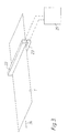
- Fig. 3 shows a second embodiment of a readout station using readout method according to the present invention.
- the photostimulable phosphor sheet 1 After exposure to e.g. X-rays the photostimulable phosphor sheet 1 is fed to the readout station.
- a linear laser array line-wise stimulates the stimulable phosphor sheet 1.
- the line-wise stimulation of the phosphor plate 1 can be done by use of several light sources.
- the light source itself can be linear shaped or a suitable optical arrangement can be used to obtain a light line on the phosphor plate. This can be done by use of e.g. fibre optics which can convert the light of a point-like light source into an elongated light line for stimulating the phosphor.
- the stimulating light source providing the stimulating light for stimulating the phosphor can be any lamp, such as Tungsten Halogen Lamps, Mercury Lamps, Xenon Lamps and Sodium Lamps.
- This light source can also be an array of LED's emitting blue (467nm), pure green (557nm), green (565nm), yellow (586nm), orange (610nm), red (660nm) or infrared (850nm) light.
- the light source can also be a laser such as Argon-ion, Krypton, frequency doubled and non frequency doubled Nd:YAG and diode lasers.
- the readout of the stimulated fluorescence is done by use of a photoconversion element which is a line sensor 23 comprising many solid state photosensitive elements and where the sensor is positioned near the line of stimulation.
- Stimulating light source 22 and the readout device 23 can be placed at the same side of the phosphor or at the opposite side.
- One such readout device is a linear CCD array.
- the fluorescence causes charge build-up in the CCD elements which, after a suitable integration time, is clocked out to a analog to digital convertor.
- After readout of one line the phosphor or the readout arrangement is transported one line further by a transporting mechanism (not shown) in the direction of arrow 24 and a new readout cycle is started.
- Other linear sensors can be used.
- One such sensor is a elongated photomultiplier having a line-like entrance window. Instead of a light line scanning the phosphor plate a dot scanning device such as a laser scanner can also be used.
- At least one pulse of predetermined length-is given to stimulate the phosphor plate After each pulse a readout period is started. The charge build-up during the stimulating light pulse is clocked out of the CCD afterwards and is not used for image detection. Immediately after this the CCD is reset at the beginning of the readout period and a new charge build-up phase is started to detect the stimulated light which is still present because of the decay of the phosphor. The detection of the stimulated light is stopped just before a new readout cycle is started for a new line.
- the sensed charges can be readout and a new stimulating pulse can be given to the same line whereafter a new charge detecting cycle for the same area is started. Doing so, a whole burst of stimulating pulses for readout of one line is given while only the charges build-up in the CCD in between the light pulses is readout. In this way a better readout of the stored image is obtained.
- the charges readout in between the stimulating pulses are supplied to a signal processing section 25 where a further processing can take place.
- One such method is the averaging of the different signals obtained resulting in a better signal to noise ratio.
- the readout period falls totally outside the predetermined stimulating periods.
- optical filters could be necessary to separate the stimulating and stimulated light it is possible to provide a certain overlap of the stimulating pulse and the readout period. By doing this the influence of she stimulating light is also less than when using a system having a continuous readout and/or continuous stimulation.
- colour filter means are preferably to be provided to prevent the stimulation light to reach the CCD.
- the colour filter means is disposed in the path between the plate and the CCD and has a certain thickness which affects the sharpness of the image. Therefore it is preferable that the colour filter is as thin as possible.
- a thin gelatine filter is preferred while it provides no adverse effect on the sharpness and has good filtering properties.
- Fig. 4. shows another embodiment according to the present invention.
- the photoelectric conversion means used in this embodiment is a two dimensional CCD sensor. In the light sensitive elements of the CCD charge build-up occurs relative to the received fluorescence light. Alternatively other two-dimensional sensors can be used. In this way a large number of pixels can be readout during the same readout cycle.
- a stored energy releasing phosphor plate 37 comprising a LiTaO 3 :Tb 3+ phosphor as described in European application EP 597 311 which is previously exposed in a x-ray apparatus (not shown) is readout in the readout apparatus in a time resolving mode.
- the storage phosphor plate 37 is stimulated by a frequency doubled Nd:YAG laser (532nm) 38.
- a Fibre Optic Plate 39 guiding the stimulating light to the phosphor plate 37 is spreading the light of the stimulating light source.
- the Fibre Optic Plate 39 is placed in direct contact with the phosphor layer 37 so that only these pixels are stimulated which will be read out.
- the light emitting ends of the fibre optic are evenly distributed facing the phosphor plate . Therefore an equal light intensity is obtained during stimulation so there is no need for shading correction of the sensed signal in the image processing section.
- the Fibre Optic Plate 40 is in close contact with the stimulated area of the phosphor layer to obtain a good resolution and a good readout efficiency.
- the apparatus employing the method thus works in a transmittance mode, i.e. while the phosphor plate is exposed to stimulating light at one side, the detection of stimulated light is done at the opposite side.
- the Fibre Optic Plate guiding the stimulated light is tapered so that the image is reduced in size. A reduction factor of 5:1 can be obtained.
- the collection efficiency of the Fibre Optic Plate itself can be as high as 80 %.
- a shutter or a rotating wheel with a slit can be used to make the light source emit intermittently.
- the LED-array and diode laser can be pulsed directly by modulating the electric current.
- the Argon and Krypton lasers can also be modulated with an acousto-optic modulator. It is clear that the used light sources are not restricted to diffraction limited light sources which is a further advantage of the system.
- the pulse time of the frequency doubled Nd:YAG laser is preferably in the range of 1% to 30% of the decay time of the phosphor luminescence.
- the time between two pulses is preferably in the range of 1 to 3 times the decay time of the phosphor luminescence.
- the CCD 41 used in this embodiment is of a two-dimensional type. This means the photosensitive sites of the CCD form a matrix structure.
- the charges are accumulated in the elements wherein the charges correspond to the sensed stimulated light intensity of a fixed position on the phosphor plate.
- the readout of the charges out of the CCD can be done in a very short time.
- the charges are clocked out of the light sensitive area and are converted to the image signal.
- the CCD can also be of the type comprising a transfer buffer 42. In this CCD sensor the charges are (simultaneously) clocked into the light insensitive transfer buffer.
- the readout of the charges out of the buffer can be conducted in a later stadium. During this readout phase the CCD need not to be kept stationary.
- the total area that can be read-out simultaneously can be made larger (e.g.50 x 50 mm).
- Several pixels are read-out simultaneously and transferring the data from the CCD to the signal processing section 43 for image processing takes only a few milliseconds. This ensures a high throughput and allows the use of a photostimulable phosphor having a decay time in the range of 1 ⁇ s to 300 ms without loss of resolution as there is no movement of the CCD relative tot the plate.
- the charge build-up during the stimulating light pulse is clocked out of the CCD afterwards and is not used for image detection.
- the CCD is reset and starts a new charge build-up phase to detect the stimulated light which is still present because of the decay of the phosphor.
- the sensed charges can be readout and a new stimulating pulse can be given whereafter a new charge detecting cycle for the same area is started. Doing so, a whole burst of stimulating pulses is given while only the charges build-up in the CCD in between the light pulses is readout.
- the phosphor can be stimulated with light having wavelengths shorter, close or equal to the wavelengths of the emitted light even if no optical filter can be found to separate them. This problem is solved by measuring the emitted light immediately after turning off the stimulation light.
- the charges readout between the stimulating pulses are supplied to a signal processing section where a further processing can take place.
- One such method is the averaging of the different signals obtained resulting in a better signal to noise ratio.
- the phosphor plate 37 or the readout arrangement After signal acquisition of one area the phosphor plate 37 or the readout arrangement is moved so that the next area can be read out.
- the stimulating light source is put off during movement.
- a new charge build-up/readout step is started at a new position after the photosensitive area of the CCD has been cleared by binning the charges out of the CCD.
- the image signals are combined by the signal processing section.
- the pixels that are read out twice give the information for the computer to adjust the position of every area.
- the final result is an electronic representation of the stored radiation image.
- the total area of the phosphor plate can be imaged onto the CCD the plate their is no need to move the light source and CCD. It is obvious that by using several two dimensional detectors (CCDs) larger areas can be readout at the same time.
Landscapes
- Physics & Mathematics (AREA)
- Health & Medical Sciences (AREA)
- Life Sciences & Earth Sciences (AREA)
- General Physics & Mathematics (AREA)
- High Energy & Nuclear Physics (AREA)
- Molecular Biology (AREA)
- Spectroscopy & Molecular Physics (AREA)
- Facsimile Scanning Arrangements (AREA)
- Radiography Using Non-Light Waves (AREA)
Abstract
- stimulating the stimulable phosphor plate (1) with stimulating light (3) during at least one stimulation time period causing the stimulable phosphor sheet to emit stimulated light ,
- detecting the stimulated light emitted by the stimulable phosphor plate by use of a photoelectric conversion means (13) during at least one readout time period,
- converting the detected stimulated light into the electrical signal representation,
Description
- exposing a stimulable phosphor plate comprising a stimulable phosphor, having a stimulating wavelength range, to the radiation image, thereby recording the radiation image on the phosphor plate,
- stimulating the stimulable phosphor plate with stimulating light having a wavelength within the stimulating wavelength range of the stimulable phosphor during at least one stimulating time period causing the stimulable phosphor sheet to emit stimulated light ,
- detecting the stimulated light emitted by the stimulable phosphor plate by use of a photoelectric conversion means during at least one readout time period,
- converting the detected stimulated light into the electrical signal representation,
Because no stimulating light is present during readout there is no need to use color filters devices or holographic filters to prevent the stimulating light reaching the detector. Therefor it is possible to put the readout detector in very close contact with the phosphor plate. This results in a further enhancement in sharpness and reduction of flare phenomena.
In either way it is impossible for the stimulating light to influence the final image obtained by the computer.
By using this readout method a part (e.g. about 20%) of the duty cycle reserved for each pixel is lost for readout, however the readout efficiency is much higher by leaving out the optical filter and the signal to noise ratio is high due to absence of stimulating light during signal readout. The 20% loss in readout time causes no great signal loss because the contribution of the fluorescence which could be detected during stimulation fis is very small compared to the amount of fluorescence fir present after the stimulation pulse . When using very intense short light pulses the fluorescence emitted during stimulation can be neglected compared to the measured fluorescence during the following readout period. A time diagram of the fluorescence using such a short light pulse is given in Fig. 2B.
When the intensity of the emitted light becomes too small during readout of one line the sensed charges can be readout and a new stimulating pulse can be given to the same line whereafter a new charge detecting cycle for the same area is started. Doing so, a whole burst of stimulating pulses for readout of one line is given while only the charges build-up in the CCD in between the light pulses is readout. In this way a better readout of the stored image is obtained.
Claims (7)
- Method of obtaining an electrical representation of a radiation image comprising the steps of :characterised in that at least one of said readout time periods lies at least partially outside said stimulation time period(s).exposing a stimulable phosphor plate comprising a stimulable phosphor having a stimulating wavelength range to said radiation image, thereby recording said radiation image on said phosphor plate,stimulating said stimulable phosphor plate with stimulating light having a wavelength within said stimulating wavelength range of said stimulable phosphor during at least one stimulation time period causing said stimulable phosphor sheet to emit stimulated light ,detecting said stimulated light emitted by said stimulable phosphor plate by use of a photoelectric conversion means during at least one readout time period,converting the detected stimulated light into said electrical signal representation,
- Method according to claim 1 wherein at least one of said readout time period(s) lies totally outside said stimulation time periods.
- Method according to any of the preceding claims, wherein said stimulation of said stimulable phosphor plate is done by pulsed light.
- Method according to any of the preceding claims wherein said stimulation of said phosphor plate is done using a laser scanner.
- Method according to any of the preceding claims where said photoelectric conversion means is a line sensor.
- Method according to any of the preceding claims where said photoelectric conversion means is a two dimensional matrix sensor.
- Method according claim 1 where said photoelectric conversion means is a CCD sensor.
Priority Applications (1)
| Application Number | Priority Date | Filing Date | Title |
|---|---|---|---|
| EP98200165A EP0862066B1 (en) | 1997-01-31 | 1998-01-22 | Method for readout af a stimulable phosphor screen |
Applications Claiming Priority (3)
| Application Number | Priority Date | Filing Date | Title |
|---|---|---|---|
| EP97200267 | 1997-01-31 | ||
| EP97200267 | 1997-01-31 | ||
| EP98200165A EP0862066B1 (en) | 1997-01-31 | 1998-01-22 | Method for readout af a stimulable phosphor screen |
Publications (2)
| Publication Number | Publication Date |
|---|---|
| EP0862066A1 true EP0862066A1 (en) | 1998-09-02 |
| EP0862066B1 EP0862066B1 (en) | 2004-08-25 |
Family
ID=26146096
Family Applications (1)
| Application Number | Title | Priority Date | Filing Date |
|---|---|---|---|
| EP98200165A Expired - Lifetime EP0862066B1 (en) | 1997-01-31 | 1998-01-22 | Method for readout af a stimulable phosphor screen |
Country Status (1)
| Country | Link |
|---|---|
| EP (1) | EP0862066B1 (en) |
Cited By (5)
| Publication number | Priority date | Publication date | Assignee | Title |
|---|---|---|---|---|
| US6800870B2 (en) | 2000-12-20 | 2004-10-05 | Michel Sayag | Light stimulating and collecting methods and apparatus for storage-phosphor image plates |
| WO2005064912A3 (en) * | 2003-12-19 | 2005-12-08 | Orex Computed Radiography | Methods and apparatus for pulsed radiation image acquisition |
| EP1065525A3 (en) * | 1999-07-02 | 2006-04-05 | Agfa-Gevaert | Radiation image read out apparatus |
| US7244955B2 (en) | 2005-12-15 | 2007-07-17 | General Electric Company | Computed radiography systems and methods of use |
| CN110609314A (en) * | 2019-10-30 | 2019-12-24 | 北京物资学院 | A scintillator afterglow test device |
Citations (4)
| Publication number | Priority date | Publication date | Assignee | Title |
|---|---|---|---|---|
| US4814617A (en) * | 1984-10-11 | 1989-03-21 | Fuji Photo Film Co., Ltd. | Radiation image read-out apparatus |
| US4880987A (en) * | 1984-04-27 | 1989-11-14 | Fuji Photo Film Co., Ltd. | Radiation image read-out apparatus |
| US4983834A (en) * | 1985-10-10 | 1991-01-08 | Quantex Corporation | Large area particle detector system |
| EP0598949A1 (en) * | 1992-11-25 | 1994-06-01 | Agfa-Gevaert N.V. | Radiation image read-out method |
Family Cites Families (1)
| Publication number | Priority date | Publication date | Assignee | Title |
|---|---|---|---|---|
| JPS60121439A (en) * | 1983-12-05 | 1985-06-28 | Fuji Photo Film Co Ltd | Radiation picture information reader |
-
1998
- 1998-01-22 EP EP98200165A patent/EP0862066B1/en not_active Expired - Lifetime
Patent Citations (4)
| Publication number | Priority date | Publication date | Assignee | Title |
|---|---|---|---|---|
| US4880987A (en) * | 1984-04-27 | 1989-11-14 | Fuji Photo Film Co., Ltd. | Radiation image read-out apparatus |
| US4814617A (en) * | 1984-10-11 | 1989-03-21 | Fuji Photo Film Co., Ltd. | Radiation image read-out apparatus |
| US4983834A (en) * | 1985-10-10 | 1991-01-08 | Quantex Corporation | Large area particle detector system |
| EP0598949A1 (en) * | 1992-11-25 | 1994-06-01 | Agfa-Gevaert N.V. | Radiation image read-out method |
Cited By (8)
| Publication number | Priority date | Publication date | Assignee | Title |
|---|---|---|---|---|
| EP1065525A3 (en) * | 1999-07-02 | 2006-04-05 | Agfa-Gevaert | Radiation image read out apparatus |
| US6800870B2 (en) | 2000-12-20 | 2004-10-05 | Michel Sayag | Light stimulating and collecting methods and apparatus for storage-phosphor image plates |
| US7589341B2 (en) | 2000-12-20 | 2009-09-15 | Michel Sayag | Light stimulating and collecting methods and apparatus for storage-phosphor image plates |
| US7825394B2 (en) | 2000-12-20 | 2010-11-02 | Michel Sayag | Light stimulating and collecting methods and apparatus for storage-phosphor image plates |
| WO2005064912A3 (en) * | 2003-12-19 | 2005-12-08 | Orex Computed Radiography | Methods and apparatus for pulsed radiation image acquisition |
| US7244955B2 (en) | 2005-12-15 | 2007-07-17 | General Electric Company | Computed radiography systems and methods of use |
| US7550754B2 (en) | 2005-12-15 | 2009-06-23 | General Electric Company | Method for registering a storage phosphor screen |
| CN110609314A (en) * | 2019-10-30 | 2019-12-24 | 北京物资学院 | A scintillator afterglow test device |
Also Published As
| Publication number | Publication date |
|---|---|
| EP0862066B1 (en) | 2004-08-25 |
Similar Documents
| Publication | Publication Date | Title |
|---|---|---|
| US5998802A (en) | Method for obtaining an electrical representation of a radiation image using CCD sensors | |
| US20010012386A1 (en) | Method for readout of a stimulable phosphor screen | |
| JPS5889244A (en) | Reading out of radioactive image information | |
| JPS6046166A (en) | Reader of radiation picture information | |
| EP1798576B1 (en) | Computed radiography system | |
| JPS5915843A (en) | Radiation analysis of structure | |
| JP3481657B2 (en) | Method for determining the maximum signal to be canceled in a photostimulable phosphor reader | |
| JPS5867240A (en) | System for reading out radioactive image information | |
| EP0862066B1 (en) | Method for readout af a stimulable phosphor screen | |
| JPH0310084B2 (en) | ||
| JPS59232337A (en) | Reading method of radiant ray image information | |
| EP0859244B1 (en) | Method for obtaining a radiation image using CCD sensors | |
| US6977388B2 (en) | Method for reading radiation image information | |
| JPH0617983B2 (en) | Radiation image information reading method and apparatus | |
| US20060219963A1 (en) | X-ray sensor | |
| JPH05208000A (en) | Energy subtraction image forming device | |
| US6504168B2 (en) | Radiation image read-out method and apparatus | |
| JPS6292659A (en) | Reading method for radiographic information | |
| JPS59211264A (en) | Radiation image detecting method | |
| JPS5867241A (en) | Apparatus for reading out radioactive image information | |
| JPH0358099B2 (en) | ||
| JPS6011836A (en) | Radiation image converter | |
| JPH0599753A (en) | Method for detecting infrared image and its detector | |
| JPS6186743A (en) | Method for reading and erasing radiant-ray image information and its device | |
| JPH1138531A (en) | Radiation picture reading method and device |
Legal Events
| Date | Code | Title | Description |
|---|---|---|---|
| PUAI | Public reference made under article 153(3) epc to a published international application that has entered the european phase |
Free format text: ORIGINAL CODE: 0009012 |
|
| AK | Designated contracting states |
Kind code of ref document: A1 Designated state(s): BE DE FR GB |
|
| 17P | Request for examination filed |
Effective date: 19990302 |
|
| AKX | Designation fees paid |
Free format text: BE DE FR GB |
|
| RBV | Designated contracting states (corrected) |
Designated state(s): BE DE FR GB |
|
| RAP1 | Party data changed (applicant data changed or rights of an application transferred) |
Owner name: AGFA-GEVAERT |
|
| 17Q | First examination report despatched |
Effective date: 20030916 |
|
| GRAP | Despatch of communication of intention to grant a patent |
Free format text: ORIGINAL CODE: EPIDOSNIGR1 |
|
| GRAS | Grant fee paid |
Free format text: ORIGINAL CODE: EPIDOSNIGR3 |
|
| GRAA | (expected) grant |
Free format text: ORIGINAL CODE: 0009210 |
|
| AK | Designated contracting states |
Kind code of ref document: B1 Designated state(s): BE DE FR GB |
|
| PG25 | Lapsed in a contracting state [announced via postgrant information from national office to epo] |
Ref country code: BE Free format text: LAPSE BECAUSE OF FAILURE TO SUBMIT A TRANSLATION OF THE DESCRIPTION OR TO PAY THE FEE WITHIN THE PRESCRIBED TIME-LIMIT Effective date: 20040825 |
|
| REG | Reference to a national code |
Ref country code: GB Ref legal event code: FG4D |
|
| REF | Corresponds to: |
Ref document number: 69825802 Country of ref document: DE Date of ref document: 20040930 Kind code of ref document: P |
|
| REG | Reference to a national code |
Ref country code: GB Ref legal event code: 746 Effective date: 20040921 |
|
| PG25 | Lapsed in a contracting state [announced via postgrant information from national office to epo] |
Ref country code: DE Free format text: LAPSE BECAUSE OF FAILURE TO SUBMIT A TRANSLATION OF THE DESCRIPTION OR TO PAY THE FEE WITHIN THE PRESCRIBED TIME-LIMIT Effective date: 20041126 |
|
| ET | Fr: translation filed | ||
| PLBE | No opposition filed within time limit |
Free format text: ORIGINAL CODE: 0009261 |
|
| STAA | Information on the status of an ep patent application or granted ep patent |
Free format text: STATUS: NO OPPOSITION FILED WITHIN TIME LIMIT |
|
| 26N | No opposition filed |
Effective date: 20050526 |
|
| REG | Reference to a national code |
Ref country code: GB Ref legal event code: 732E |
|
| REG | Reference to a national code |
Ref country code: FR Ref legal event code: TP |
|
| PGFP | Annual fee paid to national office [announced via postgrant information from national office to epo] |
Ref country code: GB Payment date: 20121218 Year of fee payment: 16 |
|
| PGFP | Annual fee paid to national office [announced via postgrant information from national office to epo] |
Ref country code: FR Payment date: 20130107 Year of fee payment: 16 |
|
| GBPC | Gb: european patent ceased through non-payment of renewal fee |
Effective date: 20140122 |
|
| REG | Reference to a national code |
Ref country code: FR Ref legal event code: ST Effective date: 20140930 |
|
| PG25 | Lapsed in a contracting state [announced via postgrant information from national office to epo] |
Ref country code: FR Free format text: LAPSE BECAUSE OF NON-PAYMENT OF DUE FEES Effective date: 20140131 Ref country code: GB Free format text: LAPSE BECAUSE OF NON-PAYMENT OF DUE FEES Effective date: 20140122 |