EP0862050A2 - Modified concentric spectrograph - Google Patents
Modified concentric spectrograph Download PDFInfo
- Publication number
- EP0862050A2 EP0862050A2 EP98301487A EP98301487A EP0862050A2 EP 0862050 A2 EP0862050 A2 EP 0862050A2 EP 98301487 A EP98301487 A EP 98301487A EP 98301487 A EP98301487 A EP 98301487A EP 0862050 A2 EP0862050 A2 EP 0862050A2
- Authority
- EP
- European Patent Office
- Prior art keywords
- spectrograph
- lens
- light
- grating
- primary
- Prior art date
- Legal status (The legal status is an assumption and is not a legal conclusion. Google has not performed a legal analysis and makes no representation as to the accuracy of the status listed.)
- Withdrawn
Links
Images




Classifications
-
- G—PHYSICS
- G01—MEASURING; TESTING
- G01J—MEASUREMENT OF INTENSITY, VELOCITY, SPECTRAL CONTENT, POLARISATION, PHASE OR PULSE CHARACTERISTICS OF INFRARED, VISIBLE OR ULTRAVIOLET LIGHT; COLORIMETRY; RADIATION PYROMETRY
- G01J3/00—Spectrometry; Spectrophotometry; Monochromators; Measuring colours
- G01J3/12—Generating the spectrum; Monochromators
- G01J3/18—Generating the spectrum; Monochromators using diffraction elements, e.g. grating
-
- G—PHYSICS
- G01—MEASURING; TESTING
- G01J—MEASUREMENT OF INTENSITY, VELOCITY, SPECTRAL CONTENT, POLARISATION, PHASE OR PULSE CHARACTERISTICS OF INFRARED, VISIBLE OR ULTRAVIOLET LIGHT; COLORIMETRY; RADIATION PYROMETRY
- G01J3/00—Spectrometry; Spectrophotometry; Monochromators; Measuring colours
- G01J3/02—Details
-
- G—PHYSICS
- G01—MEASURING; TESTING
- G01J—MEASUREMENT OF INTENSITY, VELOCITY, SPECTRAL CONTENT, POLARISATION, PHASE OR PULSE CHARACTERISTICS OF INFRARED, VISIBLE OR ULTRAVIOLET LIGHT; COLORIMETRY; RADIATION PYROMETRY
- G01J3/00—Spectrometry; Spectrophotometry; Monochromators; Measuring colours
- G01J3/02—Details
- G01J3/0205—Optical elements not provided otherwise, e.g. optical manifolds, diffusers, windows
- G01J3/0208—Optical elements not provided otherwise, e.g. optical manifolds, diffusers, windows using focussing or collimating elements, e.g. lenses or mirrors; performing aberration correction
-
- G—PHYSICS
- G01—MEASURING; TESTING
- G01J—MEASUREMENT OF INTENSITY, VELOCITY, SPECTRAL CONTENT, POLARISATION, PHASE OR PULSE CHARACTERISTICS OF INFRARED, VISIBLE OR ULTRAVIOLET LIGHT; COLORIMETRY; RADIATION PYROMETRY
- G01J3/00—Spectrometry; Spectrophotometry; Monochromators; Measuring colours
- G01J3/02—Details
- G01J3/0256—Compact construction
-
- G—PHYSICS
- G01—MEASURING; TESTING
- G01J—MEASUREMENT OF INTENSITY, VELOCITY, SPECTRAL CONTENT, POLARISATION, PHASE OR PULSE CHARACTERISTICS OF INFRARED, VISIBLE OR ULTRAVIOLET LIGHT; COLORIMETRY; RADIATION PYROMETRY
- G01J3/00—Spectrometry; Spectrophotometry; Monochromators; Measuring colours
- G01J3/02—Details
- G01J3/0262—Constructional arrangements for removing stray light
Definitions
- This invention relates to diffraction-grating spectrographs. More particularly, this invention relates to concentric diffraction-grating spectrographs with modified arrangements of their optical components.
- An optical spectrograph collects light at its entrance slit and forms an image of the entrance slit in the exit plane at the wavelengths present in the light source.
- Diffraction-grating spectrographs use one or more diffraction gratings to diffract light into specific wavelengths and to select a predetermined portion of the wavelengths present in that light.
- Concentric spectrographs are particularly well suited for applications requiring sharp spectral and spatial imaging.
- One type of concentric spectrograph includes an entrance port, an exit port, a hemispheric field lens, and a concave diffraction grating that has a set of substantially parallel grating lines, or grooves.
- a concave grating has a reflective grating surface ruled on a concave surface, usually spherical, that disperses the light and focuses the spectrum.
- One advantage of such a grating is that it can be used without separate collimating optics.
- a concave grating inherently has an optical axis, which is a line that passes symmetrically through the center of curvature of the grating surface, and a meridian plane, which is a plane that contains the grating optical axis and that is substantially perpendicular to the grating lines.
- the entrance and exit ports of a conventional concentric spectrograph are positioned substantially in the meridian plane of the grating.
- a conventional concentric spectrograph operates as follows. First, a light beam enters the spectrograph through the entrance port, which is substantially in the meridian plane of the grating. After passing through the entrance port, the light beam passes through the hemispherical lens, which causes the beam to diverge and form an expanding light cone. The longitudinal axis of that expanding light cone lies in the meridian plane of the grating. Next, the light beam is reflectively diffracted by the grating surface toward the lens in the form of a contracting light cone. The longitudinal axis of the contracting light cone also lies in the meridian plane. Once the light is incident on the surface of the lens, most of the light is transmitted by the lens and focused at the exit port for spectral analysis.
- concentric spectrographs form sharp images due to the inherent absence of Seidel aberrations.
- concentric spectrographs can be designed with relatively large numerical apertures (e.g., numerical apertures greater than 0.7 are possible).
- concentric spectrographs are anastigmatic, flat field devices in which linear dispersion is a function of groove density and wavelength.
- concentric spectrographs provide equal magnification along and across the dispersion, which is important for convolution applications.
- concentric spectrographs do not require the use of aspherical optical surfaces, which are relatively expensive.
- concentric spectrographs have difficulty preventing stray light from contaminating with the desired spectrum at the exit port of the spectrograph. Stray light may arise from a number of sources. Of particular concern is light which has been reflectively diffracted twice. Some of that light is directed toward the exit port, which appears as a faint undesirable spectrum that overlaps with the desired spectrum, a phenomenon called spectral overlap.
- one or more filters may be placed along the optical path of the light beam, especially between the exit port of the spectrograph and the detector. Filtering, however, only works when the stray light has a different quality than the desired light, such as a different wavelength or polarization. When the wavelengths of the stray and spectral light are the same, conventional wavelength filtering techniques will not work. In any case, filtering reduces the intensity of the desired spectrum, which reduces the throughput of the spectrograph. Therefore, it would be desirable to provide a high throughput concentric spectrograph, which also has high stray light rejection without the use of filters.
- F-number refers to the ratio of an equivalent focal length of a lens to the diameter of its entrance pupil.
- F-number refers to the ratio of an equivalent focal length of a lens to the diameter of its entrance pupil.
- Embodiments of this invention aim to provide a modified concentric spectrograph for dispersing polychromatic light with increased stray light rejection at the exit port.
- Another aim is to provide a modified concentric spectrograph that can be used to simultaneously disperse light from one or more polychromatic light sources.
- a further aim is to provide a modified concentric spectrograph which is compact, relatively inexpensive to manufacture, and relatively immune to miscalibration.
- a still further aim is to provide a modified concentric spectrograph that has a small F-number.
- a yet further aim is to provide an improved concentric spectrograph that can be constructed with conventional optical components.
- a modified concentric spectrograph with reduced stray light includes a diffraction grating, a lens, an entrance port, and an exit port.
- the grating is a concave type diffraction grating that (1) has a concave grating surface and (2) defines an optical axis and a meridian plane that contains that axis.
- the meridian plane has a first side and a second side.
- the lens has a substantially planar surface, a convex surface, and an optical axis.
- the lens is positioned so that its convex surface faces the concave surface of the grating and its optical axis is substantially coaxial with the optical axis of the grating.
- the entrance port is located substantially on the first side of the meridian plane and the exit port is located substantially on the second side of the meridian plane.
- at least one of the ports faces the planar surface of the lens and is close to a focal plane, the location of which is determined by various factors, including the radii of curvature of the lens and grating.
- a method by which the modified spectrograph operates is also provided.
- polychromatic light passes through the entrance port, which is located at a perpendicular distance from the meridian plane.
- the light is directed through the lens toward the grating surface so that the light is incident on that surface.
- the light is reflectively diffracted by the grating surface, thereby dispersing the light.
- the dispersed light is imaged with the lens at an exit port located substantially out of the meridian plane.
- a modified concentric spectrograph that includes multiple entrance and exit ports and a method of its use are also provided.
- Embodiments of the present invention provide a method and apparatus for diffracting polychromatic light using a modified concentric spectrograph.
- polychromatic light is diffracted and imaged at an exit port with high resolution and increased stray light rejection.
- Prior art concentric spectrographs include an entrance port, an exit port, a hemi-spherical lens, and a concave diffraction grating, which has a meridian plane.
- a beam of light enters the spectrograph through the entrance port and propagates substantially in and along the meridian plane until the diffracted light exits the spectrograph at the exit port. Therefore, the entrance and exit ports are positioned substantially in the meridian plane.
- an image is also formed by negative second order light because a portion of that negative second order light is diffracted twice by the grating due to internal reflection and focused by the lens at the same place as the first order light -- thereby mixing those orders at the exit port.
- a preferred modified concentric spectrograph is provided that reduces the amount of spectral overlap at the exit port, yet substantially preserves the high image quality there.
- the gratings and lenses of the embodiments of this invention may be arranged a similar way to a
- the entrance and exit ports are arranged differently.
- the entrance and exit ports of a known concentric spectrograph are substantially centered in the meridian plane of the grating.
- the entrance and exit ports of a modified concentric spectrograph are located substantially out of the meridian plane.
- substantially no negative second order light is reimaged at the exit port overlapping the order of interest for the following reason.
- a first portion of the negative second order light passes through the lens and is focused away from the exit port. Therefore, this first portion of the negative second order does not mix with the negative first order at the exit port.
- a second portion of the negative second order light is reflected by the surface of the lens back toward the grating and reflectively diffracted for a second time.
- the second portion of the negative second order light, as well as the negative first order light is focused at the exit port.
- this second portion of negative second order light is not reflected back toward the exit port; the modified arrangement directs this second portion away from the exit port.
- mixing between negative first and negative second orders is substantially eliminated at the exit port of a spectrograph constructed in accordance with this invention.
- the present invention may further include a housing for mounting any of the grating, lens, and ports.
- a housing for mounting any of the grating, lens, and ports.
- the primary entrance and exit ports of embodiments of modified spectrograph constructed in accordance with the present invention are substantially out, and on different sides, of the meridian plane of the grating. However, the ports are operational in many positions on those sides.
- the entrance and exit ports are positioned at an optical length from the planar surface of the lens, preferably near the primary focal plane of the spectrograph.
- the position of the primary focal planes is determined by the curvature of the lens and the grating, their relative positions, and the refractive index of the material between the lens and the exit port (e.g., glass, air, etc.).
- the optical length increases when the curvature of the lens and grating increases.
- the optical length increases when the refractive index of the medium between the lens and the exit port increases.
- the entrance and exit ports may be positioned near secondary, or modified, focal planes. These modified planes are different and preferably remote from the primary focal plane position. This provides more space at the ports for mounting additional optical instrumentation, such as optical detectors and cryostats.
- a reflective surface may be added by adding an optical prism with a reflective surface.
- the reflective surface is disposed on the hypotenuse of a right triangular block. In this way, the light propagates in the prism and reflects internally from that reflective surface.
- the addition of the prism changes the optical path length at that port.
- the thickness of the lens at that port is preferably reduced.
- the optical path lengths at both ports are preferably substantially similar. Therefore, when a prism is placed at one port, a second prism, an optical block, or a combination of both, is preferably placed at the other port.
- any number of optically transmissive bodies may be placed at each port, as long as the optical path lengths at both port are within the design constraints of the spectrograph.
- the optica-lly transmissive material used to form each optical body may be the same or different. Optically transmissive materials that have a large index of refraction can be used to elongate the effective focal length of the lens.
- one or more optically transmissive plates that have a large index of refraction may be used, in addition to optical blocks and prisms, to further adjust the effective focal length of the lens.
- modified focal planes may be oriented in any direction and fall on either side of the meridian plane using conventional optical techniques.
- a preferred method for using an embodiment of spectrograph built in accordance with the principles of the present invention is also provided.
- polychromatic light passes through an entrance port located on one side of the meridian plane of a concave diffraction grating.
- a lens is used to direct the light toward a concave grating surface of the grating so that the light is incident on the grating surface at least in the meridian plane.
- the light is diffracted by the diffraction grating.
- the diffracted light is imaged with the same lens at an exit port which is located on the other side of the meridian plane.
- an embodiment of modified concentric spectrograph having multiple pairs of entrance and exit ports is provided.
- Such a spectrograph has at least two pairs of entrance and exit ports.
- the optical components that make up the multiple pair embodiment are essentially the same as the previously described single pair embodiment, except that the multiple pair embodiment has an extra pair of entrance and exit ports.
- the secondary ports like the primary ports, are preferably located near a focal plane of the spectrograph, but should not substantially overlap with the primary ports.
- this spectrograph may include a housing for mounting some or all of the optical components and for preventing stray light from interfering with the spectra at the exit ports.
- a method for diffracting two beams of light using a multi-port spectrograph is also provided.
- the beams may be diffracted simultaneously or alternatively.
- the spectrograph for use with this method includes a grating, a lens, a primary entrance port, a primary exit port, a secondary entrance port, and a secondary exit port.
- the primary ports are located on opposite sides of the meridian plane and the secondary ports are located on opposite sides of the meridian plane.
- a first polychromatic light beam is diffracted.
- the first beam is diffracted by (1) providing the first beam at the primary entrance port, (2) directing the first beam with the lens toward the grating so that the first beam is incident on the grating in the meridian plane, (3) reflectively diffracting the first beam with the grating to form a first diffracted beam, and (4) imaging the first diffracted beam with the lens at the primary exit port.
- a second polychromatic light beam is diffracted.
- the second light beam is diffracted by (1) providing the second beam at the secondary entrance port, (2) directing the second beam with the lens toward the grating so that the second beam is incident on the grating, (3) reflectively diffracting the second beam with the grating to form a second diffracted beam, and (4) imaging the second diffracted beam with the lens at the secondary exit port.
- FIGS. 5-12 A preferred embodiment of a modified concentric spectrograph according to the present invention, with several variations, is shown in FIGS. 5-12 and compared with a known concentric spectrograph, shown in FIGS. 1-4.
- known concentric spectrograph 100 includes entrance port 105, exit ports 110 and 111, hemi-spherical lens 115, and concave diffraction grating 120.
- light in the form of a beam having a central axis, enters spectrograph 100 through entrance port 105 and propagates along an optical path, such that the central axis of the beam propagates in meridian plane 125 (i.e., the X-Z plane), until the light exits spectrograph 100 at exit port 110.
- Lens 115 increases the diameter of the beam so that it substantially fills grating surface 121. After the light is reflectively diffracted by grating surface 121, lens 115 gathers the diffracted light and images it at an exit port, such as port 111.
- entrance port 105 and exit ports 110 and 111 are substantially located in meridian plane 125 of known concentric spectrograph 100. This arrangement was believed to maximize throughput and preserve the quality of the image of the diffracted light at exit ports 110 and 111. However, this arrangement, as described more fully below, has the important disadvantage of contaminating desirable diffracted light with stray light at exit port 110. Also, exit ports 110 and 111 are positioned in the meridian plane to receive positive and negative first order diffracted light, respectively. For reasons that will also be more fully described below, the following description concentrates on the use of negative first order light.
- polychromatic light propagates in known concentric spectrograph 100 along optical path legs 150-155.
- the optical path begins with leg 150, which begins at entrance port 105 and extends to planar surface 116 of lens 115.
- entrance port 105 is positioned substantially in meridian plane 125.
- light propagates in lens 115 along leg 151, which extends from planar surface 116 to convex surface 117.
- light propagates along leg 152, which extends from spherical surface 117 of lens 115 to concave surface 121 of diffraction grating 120.
- n ⁇ the order of the diffracted light (see, e.g., FIG. 9).
- Zero order light contains all wavelengths that entered entrance port 105, and represents the case when the diffraction grating acts like a mirror.
- Zero order light is imaged at point 101.
- Positive and negative order light includes light diffracted by grating 120 that satisfies the grating equation for positive and negative integers, respectively.
- the position of those ports depends on the particular spectral range of interest.
- Known concentric spectrograph 100 is normally used with negative or positive first order light for at least two reasons.
- the absolute value of the order is small, the intensity of that order is large and the angle of diffraction is small. Large intensities are desirable because it provides more light for subsequent detection. Small angles of diffraction are desirable because astigmatic aberrations are generally minimized.
- negative first order light is diffracted closer to optical axis 103 than positive first order light for certain wavelengths, aberrations in the spectral image are minimized for those wavelengths.
- One spectral range of interest is from about 350 nm to about 800 nm. Therefore, according to one embodiment of this invention, negative first order light maximizes intensity and minimizes astigmatic aberrations for this spectral range.
- first order light After diffraction by grating surface 121, negative first order light propagates along legs 153-155. First order light propagates along leg 153, which extends from concave surface 121 to convex surface 117. The majority of the first order light incident at convex surface 117 is transmitted through lens 115, along leg 154, which extends, from convex surface 117 to planar surface 116. Most first order light that reaches planar surface 116 of lens 115 passes through lens 115 toward exit port 111 along leg 155, which extends between planar surface 116 and exit port 111. Exit port 111 is positioned near primary focal plane 102 of spectrograph 100, so that negative first order light is focused near port 111.
- a portion of negative second order light is focused at exit port 111 in a known spectrograph. Therefore, a known concentric spectrograph inadequately rejects this portion of stray light. This portion of stray light is focused at the exit port in known concentric spectrograph 100 for the following reason.
- FIG. 8 shows a ray diagram of a known concentric spectrograph, where each ray represents the longitudinal axis of a beam of light (e.g., a diffraction order).
- a beam of light e.g., a diffraction order.
- Light is reflectively diffracted by grating 120 into several orders and many of these orders are reflected back toward lens 115.
- the negative second order propagates along leg 160 toward lens 115.
- a first portion of that order is transmitted through lens 115 and a second portion is reflected by lens 115.
- the first portion passes through lens 115 toward planar surface 116 along leg 161. At planar surface 116, that first portion propagates along leg 162 until the light is focused at point 112 in focal plane 102. For certain spectral ranges, point 112 is physically separate from exit port 111 in focal plane 102. Therefore, little mixing occurs between negative first order light that propagates along legs 153-155 and the first portion of negative second order light that propagates along legs 161 and 162.
- Light reflected from the surfaces of a light source and a detector may also form an image at the exit port of a known concentric spectrograph.
- a light source such as a luminescing sample surface
- a detector may be mounted for receiving diffracted light.
- the surface of the detector is not completely transmissive and reflects a portion of the light. If the detector surface is normal to the longitudinal axis of the light beam, the reflected portion will retrace its path along legs 150-155, but in a reverse order.
- modified concentric spectrograph 200 includes at least four optical elements: entrance port 205, exit port 211, lens 215, and concave diffraction grating 220.
- Optical elements 205, 211, 215, and 220 of modified spectrograph 200 may be identical, to optical elements 105, 111, 115, and 120 of known concentric spectrograph 100.
- the first element is concave diffraction grating 220, which preferably is of the reflective holographic type (such as those available from Instruments S.A., Inc., of Edison, New Jersey).
- Grating 220 has concave grating surface 221, optical axis 203, and meridian plane 225.
- Meridian plane 225 has two sides.
- the term "side" is the volume that resides above or below meridian plane 225.
- one side of meridian plane 225 is the set of points having a positive Y coordinate and the other side is the set of points having a negative Y coordinate.
- Optical axis 203 of grating 220 passes symmetrically through the center of grating 220 and is normal to surface 221 of grating 220 at point 222.
- meridian plane 225 includes grating optical axis 203 and is substantially perpendicular to axis 223 of grating lines 224.
- the second optical element is lens 215, which preferably has a planar-convex shape, including planar surface 216 and convex surface 217.
- Lens 215 also has optical axis 218 that passes symmetrically through its center.
- this invention is suitable for use with a lens having an aspherical surface (i.e., when a complementary aspherical grating is used), a lens having a spherical surface is preferred.
- the third and fourth optical elements are entrance port 205 and exit port 211, which may be of the fixed or variable slit type (such as those available from Instruments S.A., Inc., of Edison, New Jersey).
- a comparison between known concentric spectrograph 100 and modified spectrograph 200 reveals that gratings 120 and 220 and lenses 115 and 225 are arranged in similar fashions.
- entrance port 105 and exit port 205 of known concentric spectrograph 100 are arranged differently from the way entrance port 205 and exit port 211 are arranged.
- entrance port 105 and exit port 111 are substantially located in meridian plane 125 (e.g., the X-Z plane in FIGS. 1-4).
- entrance port 205 and exit port 211 are located substantially out and on different sides of meridian plane 225 (e.g., the X-Z plane in FIGS. 5-7).
- entrance port 205 is positioned at perpendicular distance 272 from meridian plane 225 (X-Z plane) in first direction 273.
- entrance port 205 is substantially on one of the two sides of meridian plane 225.
- exit port 275 is also substantially positioned at perpendicular distance 272 from meridian plane 225 in a direction opposite first direction 273, or the other side of plane 225.
- the exit port should be placed in a position that receives an order of light that maximizes throughput and minimizes astigmatism.
- the absolute value of the order is small, the intensity of that order is large and the angle of diffraction is small. A large intensity is desirable because it provides more light for subsequent detection. A small angle of diffraction is desirable because astigmatic aberrations are minimized. Therefore, lower orders are more preferable than higher orders for detection purposes, and first order is most preferable.
- negative first order is more advantageous than positive first order because the negative first order is imaged even closer to the optical axis of the lens than positive first order, thereby further minimizing astigmatic aberrations in the image.
- First entrance port 405 (which corresponds to entrance port 205 in FIG. 4) produces multiple diffraction order spectra along axis 435 (the Z axis) in a focal plane of the spectrograph (an X-Y plane). These spectra include negative first and second orders 406 and 407, positive first and second orders 408 and 409, and zero order 410.
- Entrance port 405 and its corresponding zero diffraction order 410 are symmetrically positioned on opposite sides of optical axis 403 in the primary focal plane.
- An important feature of the spectra shown in FIG. 12 is that negative first order spectrum 406 is imaged substantially closer to optical axis 403 than positive first order spectrum 408. Therefore, negative first order spectrum 406 will be more anastigmatic than positive first order spectrum 408.
- modified concentric spectrograph 200 preferably has an exit port positioned near a focal plane of the spectrograph, such as planar surface 202, to receive negative first order light.
- an exit port could be positioned to receive any non-zero order of diffracted light in accordance with the principles of this invention.
- polychromatic light preferably enters modified spectrograph 200 through entrance port 205 along leg 250.
- entrance port 205 is located out of meridian plane 225.
- the light then passes through lens 215 along leg 251, which extends from planar surface 216 to convex surface 217.
- Optical axis 218 of lens 215 is preferably substantially coaxial with optical axis 203 of grating 220.
- optical axis 218 may be parallel to and offset from optical axis 203, when such a position improves the image quality or further reduces stray light at exit port 211.
- Lens 215 is also preferably positioned so that its convex surface 217 is substantially concentric with concave surface 221 of grating 220. Then, lens 215 directs the light propagating along leg 251 toward concave surface 221 along leg 252, which extends from convex surface 217 to concave surface 221. When these optical components are positioned appropriately, that light at least partially fills concave surface 221. When the light is incident on grating surface 221, the light is diffracted by it, producing multiple orders of diffracted light.
- negative first order light propagates along legs 253-255 in modified spectrograph 200, analogous to legs 153-155 in conventional concentric spectrograph 100. After diffraction, negative first order light propagates along leg 253, which extends from concave surface 221 to convex surface 217 of lens 215. Most first order light is transmitted through lens 215 along leg 254, which extends from convex surface 217 to planar surface 216. After reaching surface 216, most first order light passes out of lens 215 toward exit port 211 along leg 255, which extends between planar surface 216 and exit port 211. Exit port 211 is preferably positioned near focal plane 202 to receive the first order light.
- negative second order light is reflectively diffracted toward lens 215 along leg 260, which extends from concave surface 221 to convex surface 217.
- a portion of the negative second order light that reaches convex surface 217 passes through lens 215 toward planar surface 216 along leg 261.
- the negative second order light propagates along leg 262 until the light is focused at region 212 near focal plane 202.
- Region 212 is physically removed from exit port 211. Therefore, like in a known concentric spectrograph, negative first order light does not substantially mix with negative second order light which was reflectively diffracted once.
- negative first order light does not substantially mix with negative second order light that has been reflectively diffracted twice at the exit port for the following reason.
- modified spectrograph 200 In known concentric spectrograph 100 (e.g., shown in FIG. 8), as already described above, some negative second order light is diffracted twice by concave surface 117 at points 122 and 123 and directed toward exit port 111. However, in modified spectrograph 200 (as shown in FIG. 9), negative second order light that is diffracted twice is not directed toward exit port 211. That is, in modified spectrograph 200, negative second order light that has been reflectively diffracted twice by grating 220 propagates along leg 266, but that light is not imaged at the same exit port at which the desired spectra is imaged. In fact, the light which has been reflectively diffracted twice may not even reach convex surface 217 for a second time.
- leg 266 the light propagating along leg 266 is directed at a different position on surface 217 of lens 215, or at an internal surface of the housing, for example, so that that light is not focused toward exit port 211.
- leg 252 which extends toward grating 225
- legs 253 and 260 which extend from grating 225
- That light may then be absorbed by an absorbing surface to ensure that it is not internally reflected within spectrograph 200 back toward exit port 211.
- negative second order light is not directed to the same place on convex surface 217 as negative second order light, that portion cannot be focused at exit port 211. Therefore, in the case of modified spectrograph 200, negative first and second orders do not substantially mix at exit port 211.
- Grating 220 has a concave spherical grating surface 221 that has a radius of curvature of about 250 mm and a diameter of about 130 mm.
- Lens 215 has a radius of curvature of about 94 mm and has a diameter of about 110 mm.
- Distance 282 between convex surface 217 and concave surface 221 is about 155 mm.
- Such an embodiment is particularly well suited for dispersing wavelengths between about 350 nm and about 800 nm and has an F-number of about 1.3.
- a person of ordinary skill in the art of optical spectroscopy could adjust these parameters for other spectral ranges.
- filters may be used with modified spectrograph 200 to further reduce stray light at exit port 211.
- One or more optical filters 270 may be placed between lens 215 and ports 205 or 220 (e.g., FIG. 9).
- One or more optical filters 271 may also be positioned between light source 277 and entrance port 205 (e.g., FIG. 10) to prevent light from any secondary light sources that may otherwise enter entrance port 205.
- one or more optical filters 370 may also be placed between lens 315 and optical block 390 or prism 391 (e.g., FIG. 11). In accordance with this invention, filters may be used as long as the changes to the optical path lengths at both ports remain within the design constraints of the spectrograph.
- Entrance port 205 preferably has a symmetric shape and a small size.
- the shape may be round, but could be square, polygonal, or any other shape useful for a particular spectroscopic application, including an elongated rectangle (e.g., a slit).
- Exit port 211 preferably has an elongated shape, preferably rectangular, having a longitudinal axis that is parallel to meridian plane 225.
- the size and shape of entrance port 205 and exit port 211 could also be variable, using any variable port device (such as the one available as Part No. 220ASLN from Instruments S.A., Inc., of Edison, New Jersey).
- An embodiment of spectrograph according to the present invention may further include a housing.
- housing 280 encloses grating 220 and lens 215. Entrance port 205 and exit port 211 may also be mounted to housing 280.
- Housing 280 reduces undesirable stray light from contaminating the polychromatic light inside housing 280 by preventing stray light from entering housing 280.
- inner surface 281 of housing 280 may undesirably reflect light toward exit port 211, but this undesirable effect can be minimized by making surface 281 absorptive, such as by making the surface dark.
- Another way that surface 281 may be made absorptive is by providing the surface with a grooved, or buttress threaded texture.
- the entrance and exit ports may be placed in a variety, of positions on their respective sides of the meridian plane.
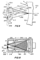
- FIG. 10 shows an embodiment of this invention in which primary focal plane 202 is located optical length 203 from planar surface 216 of lens 215.
- entrance port 205 and exit port 211 are both located near primary focal plane 202.
- either port may be positioned in or near a modified focal plane.
- FIG. 11 shows exit port 311 near focal plane 302 and entrance port 305 near modified focal plane 372. Entrance port 305 is now more physically remote from exit port 311, which provides more space at ports 305 and 311 for mounting additional optical instrumentation, such as large optical detectors, cryostats, etc.
- One way in which the entrance port may be added or moved to a modified focal plane is by the addition of reflective surface 350 between the primary focal plane 302 and lens 315, which is usually between the primary entrance port and the lens.
- Reflective surface 350 could be fixed in the spectrograph or removable, which allows a user to select a primary or secondary port.
- Reflective surface 350 may be provided in a number of ways. One such way is by the addition of optical block 390 and optical prism 391.
- Optical prism 391 is preferably formed from optically transmissive material, such as glass, and has reflective surface 350 disposed on a planar surface thereof.
- Optical prism 391 preferably has the shape of a right triangle, so that the value of angles 398 and 399 are about 45 degrees.
- Optical block 390 is also preferably formed from an optically transmissive material, possibly from the same material which optical prism 391 and lens 315 is formed.
- optical length 392 and the sum of optical lengths 395 and 396 are substantially the same when the physical lengths are substantially the same.
- the index of refraction of the optically transmissive materials will in part determine the effective focal length of the lens and spectrograph.
- Optical length 392 corresponds to the distance between exit port 311 and planar surface 316.
- the sum of optical lengths 395 and 396 corresponds to the distance between entrance port 305 and planar surface 316.
- modified spectrograph 300 can provide high quality images at high resolution with excellent stray light rejection at exit port 311.
- entrance port 205 and exit port 211 can be positioned on the same side of meridian plane 225 using one or more reflective surfaces.
- one or more optically transmissive plates that have a large index of refraction may be placed in the optical path of the spectrograph, in addition to the optical block and the optical prism, to further adjust the effective focal length of the lens.
- optically transnissive plates 233 may be placed between ports 205 or 211 and lens 215.
- optically transmissive plates 333 may be placed between: (1) optical prism 391 and lens 315 or entrance port 305, as well as between (2) optical block 390 and lens 315 or exit port 311.
- One optically transmissive material that has a large index of refraction is sapphire.
- FIGS. 12 and 13 show optical axial views (along the Z axis) of spectrographs 400 and 500, each of which have two pairs of entrance and exit ports. As explained more fully below, both pairs of ports on each instrument are similar to the single pair of ports shown in spectrograph 200 of FIG. 7.
- modified concentric spectrograph 400 shown in FIG. 12, includes grating 420, lens 415, primary entrance port 405, primary exit port 411, secondary entrance port 475, and secondary exit port 481.
- Grating 420 has an intrinsic optical axis 403, meridian plane 425, and real concave surface 421.
- grating surface 421 is spherically shaped.
- Grating 420 has grating lines 430, which are oriented in a direction substantially perpendicular to meridian plane 425.
- Lens 415 is the same as lens 215, and therefore has a substantially planar surface, a convex surface, and optical axis 403. The convex surface of lens 415 faces the concave surface of grating 420.
- optical axes of grating 420 and lens 415 are substantially coaxial, and the primary focal plane of spectrograph 400 is formed perpendicular to optical axis 403 and faces the planar surface of lens 415.
- spectrograph 400 is substantially similar to spectrograph 200, except that spectrograph 400 also has secondary entrance and exit ports 411 and 481, respectively.
- each pair of ports lies substantially on different sides of the meridian plane.
- this modified arrangement requires that a majority of the cross-sectional area of an entrance port lie on a different side of the meridian plane from its complementary exit port.
- the entire cross-sectional area of each of port lies entirely on different sides of the meridian plane.
- entrance and exit ports 405 and 411 are on different sides of meridian plane 425.
- entrance and exit ports 475 and 481 are on different sides of meridian plane 425.
- modified concentric spectrograph 400 When a spectrograph has two or more pairs of ports, the entrance port of one pair may be on different sides or the same side as an exit port of another pair.
- modified concentric spectrograph 400 is shown in FIG. 12.
- Spectrograph 400 has two entrance ports 405 and 475 on one side of meridian plane 425 and corresponding exit ports 411 and 481 on the other side of meridian plane 425.
- modified concentric spectrograph 500 Another embodiment of modified concentric spectrograph 500 is shown in FIG. 13.
- Spectrograph 500 has one entrance port and one exit port on each side of meridian plane 525. Both of these embodiments are described below.
- Spectrograph 400 is generally constructed in a fashion similar to spectrograph 200 so that exit ports 411 and 481 are positioned to receive an image of entrance ports 405 and 475 using first order light, although other orders may be used. In order to minimize astigmatism, the preferred order is the order imaged closest to the optical axis of the lens. Negative first order spectra 406 and 476 is shown imaged in exit ports 411 and 481, respectively. In addition to negative first order spectra 406 and 476, positive first order spectra 408 and 478, positive second order spectra 409 and 479, and negative second order spectra 407 and 477, which correspond to entrance ports 405 and 475, respectively, are shown in FIG. 12.
- Zero order images 410 and 480 of entrance ports 405 and 475, respectively, are also shown.
- One advantage of spectrograph 400 is that a single detector may be used to monitor the spectra of two different inputs, such as a sample and a reference. The use of a single detector can be especially useful for normalization and other calibration procedures.
- spectrograph 500 is ccnstructed in a fashion similar to spectrographs 200 and 400 so that exit ports 511 and 581 are positioned to receive an image of entrance ports 505 and 575, respectively.
- the main difference between spectrograph 400 and spectrograph 500 is that entrance ports 505 and 575 of spectrograph 500 are on different sides of meridian plane 525.
- An advantage of spectrograph 500 over spectrograph 400 is that exit ports 511 and 581 are a larger distance from one another, thereby providing additional space for mounting detection equipment and allows for the use of two separate detectors.
- negative first order spectra 506 and 576 are focused at exit ports 511 and 581, respectively.
- Zero order images 510 and 580 of entrance ports 505 and 575, respectively, are also shown in FIG. 13.
- the number of pairs of ports can be substantially greater than two and is only limited by the width of each spectra.
- spectrograph 400 may include a housing (not shown) in which grating 400 and lens 415 is placed and wherein at least one of ports 405, 475, 411, and 481 is mounted. And, the ports are preferably located near a focal plane of the spectrograph. As with concentric spectrographs generally, the convex surface of lens 415 and the concave surface of grating 420 are preferably substantially concentric.
- a method for using an embodiment of spectrograph built in accordance with the principles of the present invention is also provided.
- polychromatic light passes through an entrance port located at a perpendicular distance from the meridian plane of a concave diffraction grating.
- the light is directed using a lens toward a concave grating surface of the grating so that the light is incident on the grating surface at least in the meridian plane.
- the light is diffracted by the diffraction grating.
- the diffracted light is imaged with the same lens at the an exit port which is also located out of the meridian plane.
- a method for diffracting two beams of light using a multi-port spectrograph is also provided.
- the beams may be diffracted simultaneously or alternatively.
- the spectrograph includes a grating, a lens, a primary entrance port, a primary exit port, a secondary entrance port, and a secondary exit port.
- a first polychromatic light beam is diffracted.
- the first polychromatic light beam is diffracted by (1) providing said first polychromatic beam at the primary entrance port, (2) directing the first polychromatic beam with the lens toward the grating so that the first polychromatic beam is incident on the grating in the meridian plane, (3) reflecting the first polychromatic beam with the grating to form a first diffracted beam; and imaging the first diffracted beam with the lens at the primary exit port.
- a second polychromatic light beam is diffracted.
- the second light beam is diffracted by (1) providing the second beam at the secondary entrance port, (2) directing the second beam with the lens toward the grating so that the second beam is incident on the grating, (3) reflecting the second beam with the grating to form a second diffracted beam, and (4) imaging the second diffracted beam with the lens at the secondary exit port.
Landscapes
- Physics & Mathematics (AREA)
- Spectroscopy & Molecular Physics (AREA)
- General Physics & Mathematics (AREA)
- Spectrometry And Color Measurement (AREA)
- Lenses (AREA)
- Diffracting Gratings Or Hologram Optical Elements (AREA)
Abstract
Description
Claims (81)
- A modified concentric spectrograph comprising:a grating having an optical axis, a meridian plane, and a concave surface, said meridian plane having a first side and a second side;a lens having a substantially planar surface, a convex surface, and an optical axis, wherein said convex surface faces said concave surface, said optical axes being substantially coaxial;a primary entrance port being located substantially cut of sai idian plane toward said first side; anda primary exit port being located substantially out of said meridian plane toward said second side.
- The spectrograph of claim 1 wherein at least one of said primary ports is near said planar surface of said lens.
- The spectrograph of claim 1 wherein said primary entrance port has a cross-sectional area, and wherein a majority of said cross-sectional area is on said first side of said meridian plane.
- The spectrograph of claim 1 wherein said primary entrance port has a center, and wherein said center is on said first side of said meridian plane.
- The spectrograph of claim 3 wherein said primary exit port has a cross-sectional area, and wherein a majority of said cross-sectional area is on said second side of said meridian plane.
- The spectrograph of claim 1 wherein said primary exit port has a center, and wherein said center is on said second side of said meridian plane.
- The spectrograph of claim 1 wherein said primary entrance port and said primary exit port are located at substantially the same perpendicular distance from said meridian plane.
- The spectrograph of claim 1 wherein:said entrance port is for receiving polychromatic light from a source, said spectrograph further comprising:a housing for preventing stray light from contaminating said polychromatic light in said housing.
- The spectrograph of claim 1 further comprising at least one optical filter positioned near one of said ports.
- The spectrograph of claim 1 further comprising at least one optical filter positioned between one of said ports and said planar surface of said lens.
- The spectrograph of claim 1 further comprising:a secondary entrance port; anda reflective surface between said primary entrance port and said lens.
- The spectrograph of claim 11 wherein said reflective surface is planar and has an axis normal to said reflective surface, said axis forming an angle with said grating optical axis, said angle being about 45°.
- The spectrograph of claim 1 further comprising:a secondary exit port; anda reflective surface between said primary exit port and said lens.
- The spectrograph of claim 13 wherein said reflective surface is planar and has an axis normal to said reflective surface, said axis forming an angle with said grating optical axis, said angle being about 45°.
- A modified concentric spectrograph comprising:a grating having an optical axis, a meridian plane, and a concave surface;a lens having a substantially planar surface, a convex surface, and an optical axis, wherein said convex surface faces said concave surface, said lens optical axis is substantially coaxial with said grating optical axis, and a primary focal plane is formed perpendicular to said optical axis facing said planar surface of said lens;a primary entrance port near said primary focal plane at an intersection between a first axis and a second axis, wherein said first axis is parallel to, and offset in a first direction from, said meridian plane and said second axis is perpendicular to said meridian plane and offset from said optical axis; anda primary exit port near said primary focal plane located at a second perpendicular distance from said meridian plane, in a second direction opposite said first direction.
- The spectrograph of claim 15 wherein said entrance port is for receiving light and wherein said grating diffracts said light into at least one non-zero diffraction order, said exit port being positioned along said first axis to receive a portion of said non-zero diffraction order.
- The spectrograph of claim 16 wherein said non-zero order is an order which is imaged most closely to said optical axis.
- The spectrograph of claim 16 wherein said non-zero order is a negative first order.
- The spectrograph of claim 15 wherein said exit port is elongated along said first axis.
- The spectrograph of claim 15 further comprising at least one optical filter positioned between one of said ports and said lens.
- The spectrograph of claim 15 wherein said entrance port is for receiving light from a primary light source, said spectrograph further comprising at least one optical filter between said light source and said entrance port.
- The spectrograph of claim 15 wherein said entrance port is for receiving light from a primary light source, said spectrograph further comprising a housing for preventing light coming from a secondary light source external to said housing from contaminating said light from said primary source in said housing.
- The spectrograph of claim 22 wherein at least one of said ports is mounted to said housing.
- The spectrograph of claim 15 further comprising:a secondary entrance port; anda reflective surface between said primary entrance port and said lens, wherein said reflective surface forms a modified focal plane in which said secondary entrance port is located.
- The spectrograph of claim 15 further comprising a first body comprising an optically transmissive material, said transmissive material having an index of refraction, said first body having at least three planar surfaces whose lines of intersection are substantially parallel, a first of said first body planar surfaces being at least partially located between said primary entrance port and said lens and having a reflective surface disposed on said first plane forming a modified focal plane, a second f said first body planar surfaces facing said planar surface of said lens, and a third of said first body planar surfaces facing said modified focal plane.
- The spectrograph of claim 25 further comprising a second body comprising said optically transmissive material, said second body having at least two substantially parallel planar surfaces, a first of said parallel planar surfaces facing said primary exit port, a second of said parallel planar surfaces facing said lens.
- The spectrograph of claim 25 wherein an angle between said optical axis of said grating and an axis normal to said first of said first body planar surfaces is about 45°.
- The spectrograph of claim 27 wherein said second surface of said first body is fixedly attached to said planar surface of said lens.
- The spectrograph of claim 25 further comprising at least one optical filter positioned between said lens and said first body.
- The spectrograph of claim 26 further comprising at least one optical filter positioned between said lens and said second body.
- The spectrograph of claim 26 wherein said second surface of said second body is fixedly attached to said planar surface of said lens.
- The spectrograph of claim 31 further comprising an adhesive having an index of refraction that is substantially the same as the index of refraction of said second body for fixedly attaching said second body to said lens.
- The spectrograph of claim 26 wherein said second surface of said second body and said lens are integral.
- The spectrograph of claim 25 further comprising a secondary exit port and a reflective surface between said primary exit port and said lens, wherein said reflective surface forms a modified focal plane.
- The spectrograph of claim 15 further comprising a first body comprising an optically transmissive material, said optically transmissive material having an index of refraction, said first body having at least three planar surfaces whose lines of intersection are substantially parallel, a first of said planes being located between said primary exit port and said lens and having a reflective surface disposed on said first plane, thereby forming a modified focal plane, a second of said first body planar surfaces facing said lens planar surface, and a third of said first body planar surfaces facing said modified focal plane.
- The spectrograph of claim 35 further comprising a second body comprising said optically transmissive material, said second body having at least two substantially parallel planar surfaces, a first of said parallel planar surfaces facing said primary entrance port, a second of said parallel planar surfaces facing said lens.
- The spectrograph of claim 35 wherein an angle between said optical axis of said grating and an axis normal to said first of said reflective Surface is about 45°.
- The spectrograph of claim 35 wherein said second surface of said first body is fixedly attached to said planar surface of said lens.
- The spectrograph of claim 35 further comprising at least one optical filter positioned between said lens and said first body.
- The spectrograph of claim 36 further comprising at least one optical filter positioned between said lens and said second body.
- The spectrograph of claim 36 wherein said second face of said second body is fixedly attached to said planar surface of said lens.
- The spectrograph of claim 41 further comprising an adhesive having an index of refraction that is substantially the same as the index of refraction of said second body for fixedly attaching said second body to said lens.
- The spectrograph of claim 35 wherein said second body and said lens are integral.
- The spectrograph of claim 15 wherein at least one of said ports is substantially in one of said focal planes.
- The spectrograph of claim 15 wherein said convex surface has a center of curvature and said concave surface has a center of curvature, and wherein said centers of curvature are substantially concentric.
- A modified concentric spectrograph with reduced stray light, said spectrograph comprising:a concave grating for dispersing light having an optical axis, a meridian plane, and a concave surface;a lens having an optical axis, a planar surface, and a convex surface, wherein said optical axes are substantially coaxial, said convex surface faces said concave surface, and wherein a primary focal plane is formed facing said planar surface of said lens;an entrance port near said focal plane for permitting light to enter said spectrograph along an optical path, said entrance port being substantially located at a distance from said meridian plane in a first direction, said lens directing said light from said entrance port toward said meridian plane and said grating surface for diffraction; andan exit port located near said focal plane for permitting a portion of said light to exit said spectrograph after said light is diffraction by said grating, said lens imaging said portion of said light at said exit port.
- The spectrograph of claim 46 wherein said entrance port and said exit port are optically connected by an optical path.
- The spectrograph of claim 46 wherein at least some of said portion of said light is a non-zero order of diffracted light.
- The spectrograph of claim 48 wherein said non-zero order of diffracted light is an order that is imaged most closely to said grating optical axis at said focal plane.
- The spectrograph of claim 48 wherein said non-zero order is a negative first order.
- The spectrograph of claim 46 wherein said exit port is at said perpendicular distance from said meridian plane in a direction opposite said first direction.
- The spectrograph of claim 46 wherein said lens has an optical axis that is parallel to and offset from said grating optical axis to improve image quality and reduce stray light at said exit port.
- The spectrograph of claim 46 further comprising a housing in which said lens and said grating are placed, said housing for preventing light coming from any secondary light source outside said housing from contaminating said light in said housing.
- The spectrograph of claim 46 further comprising:a reflective surface between said entrance port and said lens, thereby forming a modified focal plane; anda secondary entrance port near said modified focal plane for receiving light from a light source.
- The spectrograph of claim 46 further comprising:a reflective surface between said exit port and said lens, thereby forming a modified focal plane; anda secondary exit port near said modified focal plane for permitting dispersed light to exit said spectrograph.
- The spectrograph of claim 46 wherein said primary entrance port and said primary exit port are located near a primary focal plane near said planar surface of said lens.
- The spectrograph of claim 46 wherein said convex surface has a center of curvature and said concave surface has a center of curvature that is substantially concentric with said convex surface center.
- A modified concentric spectrograph comprising:a grating having an optical axis, a meridian plane, and a concave surface;a lens having a substantially planar surface, a convex surface, and an optical axis, wherein said convex surface faces said concave surface, said optical axes are substantially collinear and said surfaces are substantially concentric, and a primary focal plane is formed perpendicular to said optical axis facing said planar surface of said lens;a primary entrance port near said primary focal plane at an intersection between a first primary axis and a second primary axis, wherein said first primary axis is parallel to and offset from said meridian plane and said second primary axis is perpendicular to said meridian plane and offset from said grating optical axis;a primary exit port near said primary focal plane located at a first perpendicular distance from said meridian plane, said first perpendicular distance being in a second direction opposite said first direction;a secondary entrance port near said primary focal plane at an intersection between a first secondary axis and a second secondary axis, wherein said first secondary axis is parallel to and offset from said meridian plane and said second secondary axis is perpendicular to said meridian plane and offset from said grating optical axis; anda secondary exit port near said primary focal plane located at a second/perpendicular distance from said meridian plane in said second direction.
- The spectrograph of claim 58 wherein said primary entrance port is positioned to receive polychromatic light and wherein said grating diffracts said light into at least one non-zero diffraction order, said primary exit port being positioned to receive a portion of said non-zero diffraction order.
- The spectrograph of claim 59 wherein said non-zero order is an order which is imaged most closely to said optical axis of said grating.
- The spectrograph of claim 60 wherein said non-zero order is a negative first order.
- The spectrograph of claim 58 wherein said primary entrance port is for receiving light from a primary light source, said spectrograph further comprising a housing around in which said grating and said lens is placed.
- The spectrograph of claim 58 wherein at least one of said ports is in said primary focal plane.
- A modified concentric spectrograph comprising:a grating having an optical axis, a meridian plane, and a concave surface;a lens having a substantially planar surface, a convex surface, and an optical axis, wherein said convex surface faces said concave surface, said optical axes are substantially collinear, and wherein a primary focal plane is formed perpendicular to said optical axis facing said planar surface;a first body comprising an optically transmissive material, said first body having at least three planar surfaces having lines of intersection that are substantially parallel, a first of said planes being located between said primary focal plane and said planar surface of said lens and having a reflective surface disposed thereon, a second of said first body planar surfaces facing said planar surface of said lens, and a third of said first body planar surfaces facing said modified focal plane, said reflective surface forming a modified focal plane at an optical length from said planar lens surface;a primary entrance port near said modified focal plane at an intersection between a first axis and a second axis, wherein said first axis is parallel to and offset in a first direction from said meridian plane and said second axis is perpendicular to said meridian plane; anda primary exit port near said primary focal plane located at a first perpendicular distance from said meridian plane, said first perpendicular distance being in a second direction opposite said first direction.
- The spectrograph of claim 64 further comprising a second body comprising said optically transmissive material, said second body having at least two substantially parallel planar surfaces, a first of said parallel planar surfaces facing said primary exit port, a second of said parallel planar surfaces facing said lens.
- A method for dispersing light comprising:passing polychromatic light through an entrance port located at a perpendicular distance from a meridian plane of a concave diffraction grating;directing said polychromatic light with a lens toward said grating so that said light is incident on said grating at least at said meridian plane;diffracting said light with said diffraction grating, thereby dispersing said light; andimaging said dispersed light with said lens at an exit port located out of said meridian plane.
- A method of dispersing polychromatic light comprising:passing light through a primary entrance port located substantially on a first side of a meridian plane of a grating, said grating having an optical axis and a concave surface;directing said light through a lens having a substantially planar surface, a convex surface, and an optical axis, wherein said convex surface faces said concave surface, said optical axes being substantially coaxial;diffracting at least a portion of said light with said grating; andimaging said portion of light at an exit port located substantially on said second side of said meridian plane.
- The method of claim 67 wherein said imaging comprises imaging near said planar surface of said lens.
- A method for diffracting two beams of light using a modified concentric spectrograph, said spectrograph comprising:a grating having an optical axis, a meridian plane having a first side and a second side, and a concave surface,a lens having a substantially planar surface, a convex surface, and an optical axis, wherein said convex surface faces said concave surface, said optical axes being substantially coaxial,a primary entrance port being located substantially on said first side of said meridian plane,a primary exit port being located substantially on said second side of said meridian plane,a secondary entrance port being located substantially on said first side of said meridian plane, anda secondary exit port being located substantially on said second side of said meridian plane; said method comprising:diffracting a first light beam comprising:providing said first beam at said primary entrance port,directing said first beam with said lens toward said grating so that at least a portion of said first beam is incident on said grating surface,reflectively diffracting said first beam with said grating to form a first diffracted beam, andimaging said first diffracted beam with said lens at said primary exit port; anddiffracting a second light beam comprising:providing said second beam at said secondary entrance port,directing said second beam with said lens toward said grating so that at least a portion of said second beam is incident on said grating surface,reflectively diffracting said second beam with said grating to form a second diffracted beam, andimaging said second diffracted beam with said lens at said secondary exit port.
- A method for diffracting two beams of light using a modified concentric spectrograph, said spectrograph comprising:a grating having an optical axis, a meridian plane having a first side and a second side, and a concave surface,a lens having a substantially planar surface, a convex surface, and an optical axis, wherein said convex surface faces said concave surface, said optical axes being substantially coaxial,a primary entrance port being located substantially on said first side of said meridian plane,a primary exit port being located substantially on said second side of said meridian plane,a secondary entrance port being located substantially on said second side of said meridian plane, anda secondary exit port being located substantially on said first side of said meridian plane; said method comprising:diffracting a first light beam comprising:providing said first beam at said primary entrance port,directing said first beam with said lens toward said grating so that at least a portion of said first beam is incident on said grating surface,reflectively diffracting said first beam with said grating to form a first diffracted beam, andimaging said first diffracted beam with said lens at said primary exit port; anddiffracting a second light beam comprising:providing said second beam at said secondary entrance port,directing said second beam with said lens toward said grating so that at least a portion of said second beam is incident on said grating surface,reflectively diffracting said second beam with said grating to form a second diffracted beam, andimaging said second diffracted beam with said lens at said secondary exit port.
- A concentric spectrograph for spectrally dispersing polychromatic light comprising:a grating having a concave surface and an optical axis;a lens having a substantially planar surface, a convex surface, and an optical axis, wherein said convex surface faces said concave surface, said optical axes are substantially coaxial, said convex and concave surfaces are substantially concentric, and wherein said lens and said grating are positioned at a distance to form a primary focal plane;a first port facing said planar surface of said lens;a first body comprising an optically transmissive material, said transmissive material having an index of refraction, said first body having at least three planar surfaces whose lines of intersection are substantially parallel, a first of said first body planar surfaces being at least partially located between said first port and said lens and having a reflective surface disposed on said first plane forming a modified focal plane, a second of said first body planar surfaces facing said planar surface of said lens, and a third of said first body planar surfaces facing said modified focal plane;a second port facing said planar surface of said lens and being located near said primary focal plane.
- The spectrograph of claim 71 further comprising a second body comprising said optically transmissive material, said second body having at least two substantially parallel planar surfaces, a first of said parallel planar surfaces facing said second port, a second of said parallel planar surfaces facing said lens.
- The spectrograph of claim 71 wherein an angle between said optical axis of said grating and an axis normal to said first of said first body planar surfaces is about 45°.
- The spectrograph of claim 71 wherein said second surface of said first body is fixedly attached to said planar surface of said lens.
- The spectrograph of claim 74 further comprising an adhesive having an index of refraction that is substantially the same as the index of refraction of said optically transmissive material for fixedly attaching said first body to said lens.
- The spectrograph of claim 71 wherein said first body and said lens are integral at said second surface of said first body.
- The spectrograph of claim 72 wherein said second surface of said second body is fixedly attached to said planar surface of said lens.
- The spectrograph of claim 77 further comprising an adhesive having an index of refraction that is substantially the same as the index of refraction of said second body for fixedly attaching said second body to said lens.
- The spectrograph of claim 71 further comprising one or more optically transmissive plates placed so that said polychromatic light passes through said at least one of said plates for varying the position of one of said focal planes.
- The spectrograph of claim 79 wherein said at least one of said plates is placed between one of said ports and said lens.
- The spectrograph of claim 79 wherein said at least one of said plates is placed between one of said bodies and one of said ports.
Applications Claiming Priority (4)
| Application Number | Priority Date | Filing Date | Title |
|---|---|---|---|
| US3920797P | 1997-02-28 | 1997-02-28 | |
| US39207P | 1997-02-28 | ||
| US08/884,417 US5995221A (en) | 1997-02-28 | 1997-06-27 | Modified concentric spectrograph |
| US884417 | 1997-06-27 |
Publications (2)
| Publication Number | Publication Date |
|---|---|
| EP0862050A2 true EP0862050A2 (en) | 1998-09-02 |
| EP0862050A3 EP0862050A3 (en) | 2000-04-12 |
Family
ID=26715915
Family Applications (1)
| Application Number | Title | Priority Date | Filing Date |
|---|---|---|---|
| EP98301487A Withdrawn EP0862050A3 (en) | 1997-02-28 | 1998-02-27 | Modified concentric spectrograph |
Country Status (3)
| Country | Link |
|---|---|
| US (2) | US5995221A (en) |
| EP (1) | EP0862050A3 (en) |
| JP (1) | JP3450699B2 (en) |
Cited By (9)
| Publication number | Priority date | Publication date | Assignee | Title |
|---|---|---|---|---|
| WO2001040746A1 (en) * | 1999-12-01 | 2001-06-07 | Hach Company | Concentric spectrometer with mitigation of internal specular reflections |
| WO2005095910A1 (en) * | 2004-04-01 | 2005-10-13 | Alexandr Markovich Livshits | Spectrometer |
| WO2008149939A1 (en) | 2007-06-08 | 2008-12-11 | Hamamatsu Photonics K.K. | Spectroscope |
| WO2010061090A1 (en) | 2008-11-03 | 2010-06-03 | Horiba Jobin Yvon Sas | Dyson-type imaging spectrometer having improved image quality and low distortion |
| USRE42822E1 (en) | 1997-02-28 | 2011-10-11 | Horiba Jobin-Yvon, Inc. | Modified concentric spectrograph |
| EP2157414A4 (en) * | 2007-06-08 | 2013-12-18 | Hamamatsu Photonics Kk | Spectroscopic module |
| EP2063239A4 (en) * | 2007-06-08 | 2013-12-25 | Hamamatsu Photonics Kk | Spectroscopic module |
| EP2154498A4 (en) * | 2007-06-08 | 2013-12-25 | Hamamatsu Photonics Kk | Spectroscopic module |
| US20220075164A1 (en) * | 2018-12-31 | 2022-03-10 | Soochow University | Compact, catadioptric and athermal imaging spectrometer |
Families Citing this family (29)
| Publication number | Priority date | Publication date | Assignee | Title |
|---|---|---|---|---|
| US6597452B1 (en) | 2000-11-17 | 2003-07-22 | Jobin Yvon, Inc. | Compact littrow-type scanning spectrometer |
| DE10304312A1 (en) * | 2003-02-04 | 2004-08-12 | Carl Zeiss Jena Gmbh | Compact spectrometer |
| US20050078911A1 (en) * | 2003-10-14 | 2005-04-14 | Mikes Thomas L. | System and method for using a concentric spectrometer to multiplex or demultiplex optical signals |
| EP1784622A4 (en) * | 2004-08-19 | 2009-06-03 | Headwall Photonics Inc | MULTI-CHANNEL, MULTI-SPECTRUM IMAGE SPECTROMETER |
| US7548313B2 (en) * | 2006-08-02 | 2009-06-16 | Quang-Viet Nguyen | Compact and rugged imaging Raman spectrograph |
| US7609381B2 (en) * | 2008-03-20 | 2009-10-27 | The Aerospace Corporation | Compact, high-throughput spectrometer apparatus for hyperspectral remote sensing |
| JP2009300418A (en) * | 2008-05-15 | 2009-12-24 | Hamamatsu Photonics Kk | Spectroscopic module |
| JP5205243B2 (en) * | 2008-05-15 | 2013-06-05 | 浜松ホトニクス株式会社 | Spectrometer |
| JP5512961B2 (en) * | 2008-05-15 | 2014-06-04 | 浜松ホトニクス株式会社 | Spectroscopic module and manufacturing method thereof |
| JP2009300422A (en) * | 2008-05-15 | 2009-12-24 | Hamamatsu Photonics Kk | Spectroscopic module |
| JP5205239B2 (en) * | 2008-05-15 | 2013-06-05 | 浜松ホトニクス株式会社 | Spectrometer |
| JP2009300417A (en) * | 2008-05-15 | 2009-12-24 | Hamamatsu Photonics Kk | Spectroscopic module and its manufacturing method |
| JP5205242B2 (en) * | 2008-05-15 | 2013-06-05 | 浜松ホトニクス株式会社 | Spectrometer manufacturing method |
| JP5205238B2 (en) * | 2008-05-15 | 2013-06-05 | 浜松ホトニクス株式会社 | Spectroscopic module |
| JP5207938B2 (en) | 2008-05-15 | 2013-06-12 | 浜松ホトニクス株式会社 | Spectroscopic module and method for manufacturing spectral module |
| JP5205241B2 (en) * | 2008-05-15 | 2013-06-05 | 浜松ホトニクス株式会社 | Spectroscopic module |
| JP5415060B2 (en) | 2008-05-15 | 2014-02-12 | 浜松ホトニクス株式会社 | Spectroscopic module |
| JP5205240B2 (en) * | 2008-05-15 | 2013-06-05 | 浜松ホトニクス株式会社 | Spectroscopic module manufacturing method and spectroscopic module |
| JP5438926B2 (en) * | 2008-07-16 | 2014-03-12 | オリンパス株式会社 | Spectrometer |
| US8094306B2 (en) * | 2008-08-15 | 2012-01-10 | The United States Of America As Represented By The Administrator Of The National Aeronautics And Space Administration | Micro ring grating spectrometer with adjustable aperture |
| US8174695B2 (en) * | 2008-08-15 | 2012-05-08 | The United States Of America As Represented By The Administrator Of The National Aeronautics And Space Administration | Arrayed micro-ring spectrometer system and method of use |
| US8018815B2 (en) * | 2008-08-15 | 2011-09-13 | The United States Of America As Represented By The Administrator Of The National Aeronautics And Space Administration | Micro-Fresnel zone plate optical devices using densely accumulated ray points |
| JP5666459B2 (en) * | 2008-10-20 | 2015-02-12 | ニンボ ユアンル エレクトロ−オプティクス,カンパニー リミテッド | Spectrometer comprising an aberration correcting concave diffraction grating and transmission aberration correcting means |
| WO2011143740A1 (en) * | 2010-05-18 | 2011-11-24 | Itres Research Limited | A compact, light-transfer system for use in image relay devices, hyperspectral imagers and spectrographs |
| US8511632B2 (en) | 2011-01-06 | 2013-08-20 | General Electric Company | Suspension system and method for suspending an inner vessel inside an outer vessel of a cryostat |
| WO2018070469A1 (en) * | 2016-10-14 | 2018-04-19 | 株式会社堀場製作所 | Spectroscope, and microscope provided with same |
| US10386232B2 (en) | 2017-12-15 | 2019-08-20 | Horiba Instruments Incorporated | Compact spectroscopic optical instrument |
| JP2019174151A (en) * | 2018-03-27 | 2019-10-10 | 株式会社島津製作所 | Spectrometer |
| CN115014520B (en) * | 2022-06-19 | 2025-07-11 | 苏州大学 | A spectroscopic imaging method and system for large numerical aperture snapshot imaging spectrometer |
Family Cites Families (23)
| Publication number | Priority date | Publication date | Assignee | Title |
|---|---|---|---|---|
| US2594334A (en) * | 1949-09-24 | 1952-04-29 | Beckman Instruments Inc | Fery-prism monochromator |
| US2835167A (en) * | 1954-01-20 | 1958-05-20 | Polaroid Corp | Photomicrographic apparatus |
| US2975669A (en) * | 1954-08-26 | 1961-03-21 | Jarrell Ash Company | Crossed dispersion photographic spectrometer |
| US3490848A (en) * | 1966-06-24 | 1970-01-20 | Mcpherson Instr Corp | Spectral grating apparatus |
| FR2239674B1 (en) * | 1973-08-03 | 1976-04-30 | Jobin & Yvon | |
| FR2240445B2 (en) * | 1973-08-06 | 1976-05-07 | Jobin & Yvon | |
| GB1510108A (en) * | 1974-05-28 | 1978-05-10 | Nat Res Dev | Spectrometers |
| FI54029C (en) * | 1974-06-04 | 1978-09-11 | Nils Allan Danielsson | SAETTING VIDEO COMMAND AV STIGRATION AV CONDITIONING WITH ETC CONCRETE |
| FR2334947A1 (en) * | 1975-12-10 | 1977-07-08 | Instruments Sa | FIELD SPECTOGRAPH FOR A WIDE SPECTRAL DOMAIN USING A CONCAVE HOLOGRAPHIC NETWORK |
| US4068954A (en) * | 1976-01-09 | 1978-01-17 | Instruments S.A. | Monochromator having a concave holographic grating |
| US4241999A (en) * | 1978-08-24 | 1980-12-30 | Agence Nationale De Valorisation De La Recherche (Anvar) | Monochromators |
| JPS55136918A (en) * | 1979-04-13 | 1980-10-25 | Hitachi Ltd | Aberration correcting recess diffraction grating |
| DE2924125C2 (en) * | 1979-06-15 | 1982-10-28 | Bodenseewerk Perkin-Elmer & Co GmbH, 7770 Überlingen | Device for suppressing stray light in grating monochromators |
| JPS5749822A (en) * | 1980-09-10 | 1982-03-24 | Hitachi Ltd | Photodiode array for spectro-photometer |
| US4455088A (en) * | 1982-02-10 | 1984-06-19 | Shimadzu Corporation | Monochromator with concave grating |
| JPS5979819A (en) * | 1982-10-29 | 1984-05-09 | Shimadzu Corp | Slit mechanism for spectroscope |
| JPS5981520A (en) * | 1982-10-30 | 1984-05-11 | Shimadzu Corp | Spectrometer slit mechanism |
| JPS6249308A (en) * | 1985-08-29 | 1987-03-04 | Nippon Telegr & Teleph Corp <Ntt> | Optical multiplexer/demultiplexer |
| US4850706A (en) * | 1988-03-02 | 1989-07-25 | American Holographic, Inc. | Low profile spectral analysis system |
| GB8821029D0 (en) * | 1988-09-07 | 1988-10-05 | Sira Ltd | Imaging spectrometer |
| US5066127A (en) * | 1989-08-29 | 1991-11-19 | Hyperfine, Inc. | Stigmatic imaging with spherical concave diffraction gratings |
| FR2653879B1 (en) * | 1989-10-26 | 1992-02-14 | Instruments Sa | SPECTROGRAPH WITH A CONVEX DIFFRACTION NETWORK. |
| US5995221A (en) | 1997-02-28 | 1999-11-30 | Instruments S.A., Inc. | Modified concentric spectrograph |
-
1997
- 1997-06-27 US US08/884,417 patent/US5995221A/en not_active Ceased
-
1998
- 1998-02-27 EP EP98301487A patent/EP0862050A3/en not_active Withdrawn
- 1998-02-27 JP JP04835998A patent/JP3450699B2/en not_active Expired - Lifetime
-
2001
- 2001-11-30 US US09/998,002 patent/USRE42822E1/en not_active Expired - Lifetime
Cited By (12)
| Publication number | Priority date | Publication date | Assignee | Title |
|---|---|---|---|---|
| USRE42822E1 (en) | 1997-02-28 | 2011-10-11 | Horiba Jobin-Yvon, Inc. | Modified concentric spectrograph |
| WO2001040746A1 (en) * | 1999-12-01 | 2001-06-07 | Hach Company | Concentric spectrometer with mitigation of internal specular reflections |
| WO2005095910A1 (en) * | 2004-04-01 | 2005-10-13 | Alexandr Markovich Livshits | Spectrometer |
| WO2008149939A1 (en) | 2007-06-08 | 2008-12-11 | Hamamatsu Photonics K.K. | Spectroscope |
| EP2157414A4 (en) * | 2007-06-08 | 2013-12-18 | Hamamatsu Photonics Kk | Spectroscopic module |
| EP2063239A4 (en) * | 2007-06-08 | 2013-12-25 | Hamamatsu Photonics Kk | Spectroscopic module |
| EP2154498A4 (en) * | 2007-06-08 | 2013-12-25 | Hamamatsu Photonics Kk | Spectroscopic module |
| EP2063238A4 (en) * | 2007-06-08 | 2014-01-01 | Hamamatsu Photonics Kk | SPECTROSCOPE |
| WO2010061090A1 (en) | 2008-11-03 | 2010-06-03 | Horiba Jobin Yvon Sas | Dyson-type imaging spectrometer having improved image quality and low distortion |
| US8520204B2 (en) | 2008-11-03 | 2013-08-27 | Horiba Jobin Yvon Sas | Dyson-type imaging spectrometer having improved image quality and low distortion |
| US20220075164A1 (en) * | 2018-12-31 | 2022-03-10 | Soochow University | Compact, catadioptric and athermal imaging spectrometer |
| US11579423B2 (en) * | 2018-12-31 | 2023-02-14 | Soochow University | Compact, catadioptric and athermal imaging spectrometer |
Also Published As
| Publication number | Publication date |
|---|---|
| JP3450699B2 (en) | 2003-09-29 |
| EP0862050A3 (en) | 2000-04-12 |
| USRE42822E1 (en) | 2011-10-11 |
| JPH10293062A (en) | 1998-11-04 |
| US5995221A (en) | 1999-11-30 |
Similar Documents
| Publication | Publication Date | Title |
|---|---|---|
| US5995221A (en) | Modified concentric spectrograph | |
| US7116418B2 (en) | Spectral imaging apparatus and methods | |
| US4634276A (en) | Slit imaging system using two concave mirrors | |
| US5285255A (en) | Optical system for spectral analysis | |
| US5644396A (en) | Spectrograph with low focal ratio | |
| EP0961920B1 (en) | Imaging spectrometer | |
| US6744505B1 (en) | Compact imaging spectrometer | |
| US10024716B2 (en) | Field lens corrected three mirror anastigmat spectrograph | |
| US8520204B2 (en) | Dyson-type imaging spectrometer having improved image quality and low distortion | |
| US7239386B2 (en) | Compact imaging spectrometer utilizing immersed gratings | |
| US4995721A (en) | Two-dimensional spectrometer | |
| JP7607669B2 (en) | Apparatus and method for reducing interference in an optical spectroscopy probe having a collimated sample beam - Patents.com | |
| CN108051083B (en) | Spectral imaging device | |
| US6587282B1 (en) | Broadband refractive objective for small spot optical metrology | |
| US20050073680A1 (en) | Imaging spectrometer utilizing immersed gratings with accessible entrance slit | |
| Lobb | Imaging spectrometers using concentric optics | |
| US20010048526A1 (en) | Compact spectrometer | |
| US7755775B1 (en) | Broadband optical metrology with reduced wave front distortion, chromatic dispersion compensation and monitoring | |
| US5589717A (en) | Compact spectrum analyzer module | |
| WO1997025915A1 (en) | Methods and apparatus for non-invasive glucose sensing: spectrograph | |
| WO1990002928A1 (en) | Imaging spectrometer | |
| Reininger | Imaging spectrometer/camera having convex grating | |
| KR20160143969A (en) | Spectroscopic instrument using plane mirror and lens | |
| JPS5854310A (en) | Optical system for littrow spectroscope | |
| Hopkins | Refractive elements in spectrographs |
Legal Events
| Date | Code | Title | Description |
|---|---|---|---|
| PUAI | Public reference made under article 153(3) epc to a published international application that has entered the european phase |
Free format text: ORIGINAL CODE: 0009012 |
|
| AK | Designated contracting states |
Kind code of ref document: A2 Designated state(s): AT BE CH DE DK ES FI FR GB GR IE IT LI LU MC NL PT SE |
|
| AX | Request for extension of the european patent |
Free format text: AL;LT;LV;MK;RO;SI |
|
| PUAL | Search report despatched |
Free format text: ORIGINAL CODE: 0009013 |
|
| AK | Designated contracting states |
Kind code of ref document: A3 Designated state(s): AT BE CH DE DK ES FI FR GB GR IE IT LI LU MC NL PT SE |
|
| AX | Request for extension of the european patent |
Free format text: AL;LT;LV;MK;RO;SI |
|
| AKX | Designation fees paid | ||
| REG | Reference to a national code |
Ref country code: DE Ref legal event code: 8566 |
|
| STAA | Information on the status of an ep patent application or granted ep patent |
Free format text: STATUS: THE APPLICATION IS DEEMED TO BE WITHDRAWN |
|
| 18D | Application deemed to be withdrawn |
Effective date: 20001013 |