EP0861998B1 - Engine comprising a cylinder head gasket - Google Patents
Engine comprising a cylinder head gasket Download PDFInfo
- Publication number
- EP0861998B1 EP0861998B1 EP97942239A EP97942239A EP0861998B1 EP 0861998 B1 EP0861998 B1 EP 0861998B1 EP 97942239 A EP97942239 A EP 97942239A EP 97942239 A EP97942239 A EP 97942239A EP 0861998 B1 EP0861998 B1 EP 0861998B1
- Authority
- EP
- European Patent Office
- Prior art keywords
- spacer
- gasket
- cylinder
- cylinder head
- bead
- Prior art date
- Legal status (The legal status is an assumption and is not a legal conclusion. Google has not performed a legal analysis and makes no representation as to the accuracy of the status listed.)
- Expired - Lifetime
Links
Images

Classifications
-
- F—MECHANICAL ENGINEERING; LIGHTING; HEATING; WEAPONS; BLASTING
- F02—COMBUSTION ENGINES; HOT-GAS OR COMBUSTION-PRODUCT ENGINE PLANTS
- F02F—CYLINDERS, PISTONS OR CASINGS, FOR COMBUSTION ENGINES; ARRANGEMENTS OF SEALINGS IN COMBUSTION ENGINES
- F02F11/00—Arrangements of sealings in combustion engines
- F02F11/002—Arrangements of sealings in combustion engines involving cylinder heads
-
- F—MECHANICAL ENGINEERING; LIGHTING; HEATING; WEAPONS; BLASTING
- F16—ENGINEERING ELEMENTS AND UNITS; GENERAL MEASURES FOR PRODUCING AND MAINTAINING EFFECTIVE FUNCTIONING OF MACHINES OR INSTALLATIONS; THERMAL INSULATION IN GENERAL
- F16J—PISTONS; CYLINDERS; SEALINGS
- F16J15/00—Sealings
- F16J15/02—Sealings between relatively-stationary surfaces
- F16J15/06—Sealings between relatively-stationary surfaces with solid packing compressed between sealing surfaces
- F16J15/08—Sealings between relatively-stationary surfaces with solid packing compressed between sealing surfaces with exclusively metal packing
- F16J15/0818—Flat gaskets
- F16J15/0825—Flat gaskets laminated
-
- F—MECHANICAL ENGINEERING; LIGHTING; HEATING; WEAPONS; BLASTING
- F02—COMBUSTION ENGINES; HOT-GAS OR COMBUSTION-PRODUCT ENGINE PLANTS
- F02F—CYLINDERS, PISTONS OR CASINGS, FOR COMBUSTION ENGINES; ARRANGEMENTS OF SEALINGS IN COMBUSTION ENGINES
- F02F1/00—Cylinders; Cylinder heads
- F02F1/02—Cylinders; Cylinder heads having cooling means
- F02F1/10—Cylinders; Cylinder heads having cooling means for liquid cooling
- F02F2001/104—Cylinders; Cylinder heads having cooling means for liquid cooling using an open deck, i.e. the water jacket is open at the block top face
-
- F—MECHANICAL ENGINEERING; LIGHTING; HEATING; WEAPONS; BLASTING
- F16—ENGINEERING ELEMENTS AND UNITS; GENERAL MEASURES FOR PRODUCING AND MAINTAINING EFFECTIVE FUNCTIONING OF MACHINES OR INSTALLATIONS; THERMAL INSULATION IN GENERAL
- F16J—PISTONS; CYLINDERS; SEALINGS
- F16J15/00—Sealings
- F16J15/02—Sealings between relatively-stationary surfaces
- F16J15/06—Sealings between relatively-stationary surfaces with solid packing compressed between sealing surfaces
- F16J15/08—Sealings between relatively-stationary surfaces with solid packing compressed between sealing surfaces with exclusively metal packing
- F16J15/0818—Flat gaskets
- F16J2015/085—Flat gaskets without fold over
-
- F—MECHANICAL ENGINEERING; LIGHTING; HEATING; WEAPONS; BLASTING
- F16—ENGINEERING ELEMENTS AND UNITS; GENERAL MEASURES FOR PRODUCING AND MAINTAINING EFFECTIVE FUNCTIONING OF MACHINES OR INSTALLATIONS; THERMAL INSULATION IN GENERAL
- F16J—PISTONS; CYLINDERS; SEALINGS
- F16J15/00—Sealings
- F16J15/02—Sealings between relatively-stationary surfaces
- F16J15/06—Sealings between relatively-stationary surfaces with solid packing compressed between sealing surfaces
- F16J15/08—Sealings between relatively-stationary surfaces with solid packing compressed between sealing surfaces with exclusively metal packing
- F16J15/0818—Flat gaskets
- F16J2015/0856—Flat gaskets with a non-metallic coating or strip
Definitions
- the invention relates to an engine having a cylinder head, a cylinder block and a cylinder head gasket.
- a cylinder head gasket comprising a pair of gasket baseplates held sandwiched between a cylinder head and a cylinder block and having a combustion opening formed therein in alignment with a cylinder bore, a spacer disposed around the cylinder bore to surround it in an endless manner and held sandwiched between the pair of gasket baseplates and a full bead and / or half bead formed at a suitable location or locations on the gasket baseplates (Japanese Laid-Open Utility Model Application No. 71,865 / 1992 and Japanese Laid- Open Patent Application No. 165, 167 / 1992).
- An engine according to the preamble of claim 1 is known from JP-A-07-253 162.
- the invention provides an engine with a cylinder head gasket which assures and maintains a good sealing performance in the presence of any blowhole in the casting or flaw on the mating adjoined surface.
- an engine having a cylinder head, a cylinder block in which is formed a plurality of cylinder bores, and a cylinder head gasket sandwiched between the cylinder head and the cylinder block, the cylinder head gasket including a pair of gasket baseplates having combustion openings formed therein in alignment with the cylinder bores, a spacer disposed around each combustion opening to surround it in an endless manner and sandwiched between the pair of gasket baseplates, and, for each combustion opening, a full bead and a half bead formed on each of the gasket baseplates in the regions thereof overlapping the spacer, characterised in that, for each combustion opening, the spacer, the full bead and the half bead on each gasket baseplate are continuously held sandwiched between the cylinder head and the cylinder block around the cylinder bore with both the full bead and the half bead on each gasket abutting against the spacer, and the half bead being disposed radially outwardly of
- the full bead and the half bead on each of the gasket baseplates disposed around the combustion chamber opening are held sandwiched between the cylinder head and the cylinder block, and the spacer is interposed therebetween in such region.
- This allows the full bead and the half bead to abut against the mating member under a high surface pressure and over an increased area of contact, with consequence that they are less susceptible to the influence of any gross porosity in the casting or flaw on the mating adjoined surface, thus enabling a good sealing performance to be secured.
- the engine may include, for each combustion opening, a reinforcing plate of a thickness less than that of the spacer and disposed radially outwardly of the spacer away from the bore, the reinforcing plate being held sandwiched between the pair of gasket baseplates.
- At least one of the cylinder head and the cylinder block may be formed as an open deck with cooling water passages which, for each combustion opening, surround the spacer and the full bead and the half bead on each gasket baseplate.
- Each full bead may include a centre portion extending away from the spacer in the direction of the thickness of the spacer.
- the spacers around each opening may be integrally connected together to be continuous with one another.
- the spacer may terminate radially outwardly of the opening in the region of the half bead.
- a cylinder head gasket 1 comprises a pair of gasket baseplates 3 having four combustion chamber openings 3A formed therein in alignment with respective cylinder bores 2 (see Fig. 1) and a spacer 4 disposed between the pair of gasket baseplates 3 to be held sandwiched therebetween.
- the spacer 4 is disposed around each cylinder bore 2 to surround it in an endless manner. However, in the embodiment shown, because a spacing between the cylinder bores 2, and hence, between the combustion openings 3A is reduced, four spacers 4 are integrally connected together between adjacent combustion openings 3A so as to be continuous to each other. Where there is an increased spacing between the combustion openings 3A, it will be obviously seen that the four spacers may be separate from each other.
- each gasket baseplate is formed with a full bead 3a and a half bead 3b, each of which surrounds the respective combustion opening 3A and is formed as a projection from the spacer 4.
- the full bead 3a and the half bead 3b are formed in the sequence named as viewed in a direction from the combustion openings to the outside thereof.
- SUS 301-H having a thickness of 0.20 mm may be used for each of the gasket baseplates 3.
- its opposite surfaces are coated with NBR layers 3c, as shown in Fig. 3.
- SUS 304 having a thickness of 0.08 mm may be used for the spacer 4.
- the thickness and the material of the gasket baseplate 3 may be suitably selected depending on the variety of an engine to which it is applied.
- the cylinder head gasket 1 is interposed between a cylinder head 5 and a cylinder block 6 of the engine and is held sandwiched therebetween to provide a sealing between the both by integrally connecting the cylinder head 5 and the cylinder block 6 by a clamping bolt 7.
- the spacer 4 as well as the full bead 3a and the half bead 3b on the respective gasket baseplates 3 are continuously held sandwiched between the cylinder head 5 and the cylinder block 6 along the circumference of the cylinder bore 2, thus providing a safeguard preventing a circum-ferential continuity from being interrupted or preventing part of the half bead 3b which is located on the outer side from being trapped into cooling water passages 5a, 6a formed in the adjoining surfaces of the cylinder head 5 and / or the cylinder block 6 to prevent such part from being held sandwiched.
- the cylinder head 5 and the cylinder block 6 are formed as aluminum die-cast open decked blocks, and the cooling water passages 5a, 6a are formed in the adjoining surfaces of the cylinder head 5 and the cylinder block 6, respectively, so as to surround the four combustion openings 3A in an integral manner at a location on the outside of the outermost half bead 3b.
- each of the combustion chamber openings 3A can be surrounded by the full bead 3a and the half bead 3b in an endless manner.
- the spacer 4 is disposed in the region where the full bead 3a and the half bead 3b are provided, the full bead 3a and the half bead 3b can be brought into abutment against the cylinder head 5 and the cylinder block 6 under a high surface pressure and over a relatively extensive area of contact.
- Fig. 4 shows another embodiment of the invention in which a reinforcing plate 11 of a reduced thickness than the spacer 4 is disposed on the outside of the spacer 4 of the first embodiment.
- the reinforcing plate 11 is held sandwiched between the pair of gasket baseplates 3, and a difference in the thickness between the reinforcing plate 11 and the spacer 4 in this embodiment is chosen to be equal to the thickness of the spacer 4 in the first embodiment.
- the gasket is less susceptible to the influence of any gross porosity in the casting or flaw on the mating adjoined surfaces, permitting a good sealing performance to be secured.
Landscapes
- Engineering & Computer Science (AREA)
- General Engineering & Computer Science (AREA)
- Mechanical Engineering (AREA)
- Chemical & Material Sciences (AREA)
- Combustion & Propulsion (AREA)
- Gasket Seals (AREA)
Abstract
Description
- The invention relates to an engine having a cylinder head, a cylinder block and a cylinder head gasket.
- A cylinder head gasket is known in the art comprising a pair of gasket baseplates held sandwiched between a cylinder head and a cylinder block and having a combustion opening formed therein in alignment with a cylinder bore, a spacer disposed around the cylinder bore to surround it in an endless manner and held sandwiched between the pair of gasket baseplates and a full bead and / or half bead formed at a suitable location or locations on the gasket baseplates (Japanese Laid-Open Utility Model Application No. 71,865 / 1992 and Japanese Laid- Open Patent Application No. 165, 167 / 1992).
- In the prior art, when only gasket baseplates are provided which are formed with a full bead and a half bead, they are readily susceptible to the influence of any blowhole in the casting or flaw on mating adjoined surface, causing likelihood that the sealing performance becomes degraded.
- An engine according to the preamble of
claim 1 is known from JP-A-07-253 162. - In view of the foregoing, the invention provides an engine with a cylinder head gasket which assures and maintains a good sealing performance in the presence of any blowhole in the casting or flaw on the mating adjoined surface.
- According to the present invention there is provided an engine having a cylinder head, a cylinder block in which is formed a plurality of cylinder bores, and a cylinder head gasket sandwiched between the cylinder head and the cylinder block, the cylinder head gasket including a pair of gasket baseplates having combustion openings formed therein in alignment with the cylinder bores, a spacer disposed around each combustion opening to surround it in an endless manner and sandwiched between the pair of gasket baseplates, and, for each combustion opening, a full bead and a half bead formed on each of the gasket baseplates in the regions thereof overlapping the spacer, characterised in that, for each combustion opening, the spacer, the full bead and the half bead on each gasket baseplate are continuously held sandwiched between the cylinder head and the cylinder block around the cylinder bore with both the full bead and the half bead on each gasket abutting against the spacer, and the half bead being disposed radially outwardly of the full bead away from the cylinder bore.
- With the described arrangement, the full bead and the half bead on each of the gasket baseplates disposed around the combustion chamber opening are held sandwiched between the cylinder head and the cylinder block, and the spacer is interposed therebetween in such region. This allows the full bead and the half bead to abut against the mating member under a high surface pressure and over an increased area of contact, with consequence that they are less susceptible to the influence of any gross porosity in the casting or flaw on the mating adjoined surface, thus enabling a good sealing performance to be secured.
- The engine may include, for each combustion opening, a reinforcing plate of a thickness less than that of the spacer and disposed radially outwardly of the spacer away from the bore, the reinforcing plate being held sandwiched between the pair of gasket baseplates.
- At least one of the cylinder head and the cylinder block may be formed as an open deck with cooling water passages which, for each combustion opening, surround the spacer and the full bead and the half bead on each gasket baseplate.
- Each full bead may include a centre portion extending away from the spacer in the direction of the thickness of the spacer.
- The spacers around each opening may be integrally connected together to be continuous with one another.
- For each combustion opening the spacer may terminate radially outwardly of the opening in the region of the half bead.
-
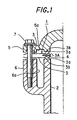
- Fig. 1 is a longitudinal section of a first embodiment of the invention;
- Fig. 2 is a plan view of
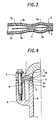
cylinder head gasket 1 shown in Fig. 1; - Fig. 3 is a cross section, to an enlarged scale, of a pertinent portion shown in Fig. 1; and
- Fig. 4 is a longitudinal section of a second embodiment of the invention.
-
- The invention will now be described below with reference to an embodiment applied to a linear four cylinder engine.
- Referring to Figs. 1 and 2, a
cylinder head gasket 1 comprises a pair ofgasket baseplates 3 having fourcombustion chamber openings 3A formed therein in alignment with respective cylinder bores 2 (see Fig. 1) and aspacer 4 disposed between the pair ofgasket baseplates 3 to be held sandwiched therebetween. - The
spacer 4 is disposed around eachcylinder bore 2 to surround it in an endless manner. However, in the embodiment shown, because a spacing between thecylinder bores 2, and hence, between thecombustion openings 3A is reduced, fourspacers 4 are integrally connected together betweenadjacent combustion openings 3A so as to be continuous to each other. Where there is an increased spacing between thecombustion openings 3A, it will be obviously seen that the four spacers may be separate from each other. - In a region overlapped by the
spacer 4, each gasket baseplate is formed with afull bead 3a and ahalf bead 3b, each of which surrounds the respective combustion opening 3A and is formed as a projection from thespacer 4. Thefull bead 3a and thehalf bead 3b are formed in the sequence named as viewed in a direction from the combustion openings to the outside thereof. - SUS 301-H having a thickness of 0.20 mm, for example, may be used for each of the
gasket baseplates 3. Preferably, its opposite surfaces are coated withNBR layers 3c, as shown in Fig. 3. For thespacer 4, SUS 304 having a thickness of 0.08 mm may be used. However, it should be understood that the thickness and the material of thegasket baseplate 3 may be suitably selected depending on the variety of an engine to which it is applied. - As shown in Fig. 1, the
cylinder head gasket 1 is interposed between acylinder head 5 and acylinder block 6 of the engine and is held sandwiched therebetween to provide a sealing between the both by integrally connecting thecylinder head 5 and thecylinder block 6 by aclamping bolt 7. - In this example, the
spacer 4 as well as thefull bead 3a and thehalf bead 3b on therespective gasket baseplates 3 are continuously held sandwiched between thecylinder head 5 and thecylinder block 6 along the circumference of thecylinder bore 2, thus providing a safeguard preventing a circum-ferential continuity from being interrupted or preventing part of thehalf bead 3b which is located on the outer side from being trapped into cooling water passages 5a, 6a formed in the adjoining surfaces of thecylinder head 5 and / or thecylinder block 6 to prevent such part from being held sandwiched. - In the embodiment shown, the
cylinder head 5 and thecylinder block 6 are formed as aluminum die-cast open decked blocks, and the cooling water passages 5a, 6a are formed in the adjoining surfaces of thecylinder head 5 and thecylinder block 6, respectively, so as to surround the fourcombustion openings 3A in an integral manner at a location on the outside of theoutermost half bead 3b. - With the described construction, each of the
combustion chamber openings 3A can be surrounded by thefull bead 3a and thehalf bead 3b in an endless manner. In addition, since thespacer 4 is disposed in the region where thefull bead 3a and thehalf bead 3b are provided, thefull bead 3a and thehalf bead 3b can be brought into abutment against thecylinder head 5 and thecylinder block 6 under a high surface pressure and over a relatively extensive area of contact. - As a consequence, it is less susceptible to the influence of any gross porosity in the casting or flaw on the adjoining surfaces of the
cylinder head 5 and thecylinder block 6, allowing a good sealing performance to be secured and maintained. - Fig. 4 shows another embodiment of the invention in which a reinforcing
plate 11 of a reduced thickness than thespacer 4 is disposed on the outside of thespacer 4 of the first embodiment. The reinforcingplate 11 is held sandwiched between the pair ofgasket baseplates 3, and a difference in the thickness between thereinforcing plate 11 and thespacer 4 in this embodiment is chosen to be equal to the thickness of thespacer 4 in the first embodiment. - Again, a similar function and effect is achieved as in the first embodiment, while allowing the rigidity of the entire
cylinder head gasket 1 to be enhanced. - As described, according to the invention, the gasket is less susceptible to the influence of any gross porosity in the casting or flaw on the mating adjoined surfaces, permitting a good sealing performance to be secured.
Claims (6)
- An engine having a cylinder head (5), a cylinder block (6) in which is formed a plurality of cylinder bores (2), and a cylinder head gasket (1) sandwiched between the cylinder head (5) and the cylinder block (6), the cylinder head gasket (1) including a pair of gasket baseplates (3) having combustion openings (3A) formed therein in alignment with the cylinder bores (2), a spacer (4) disposed around each combustion opening (3A) to surround it in an endless manner and sandwiched between the pair of gasket baseplates (3), and, for each combustion opening (3A), a full bead (3a) and a half bead (3b) formed on each of the gasket baseplates (3) in the regions thereof overlapping the spacer (4), characterised in that, for each combustion opening (3A), the spacer (4), the full bead (3a) and the half bead (3b) on each gasket baseplate (3) are continuously held sandwiched between the cylinder head (5) and the cylinder block (6) around the cylinder bore (2) with both the full bead (3a) and the half bead (3b) on each gasket baseplate (3) abutting against the spacer (4), and the half bead (3b) being disposed radially outwardly of the full bead (3a) away from the cylinder bore (2).
- An engine as claimed in claim 1 and further including, for each combustion opening (3A), a reinforcing plate (11) of a thickness less than that of the spacer (4) and disposed radially outwardly of the spacer (4) away from the bore (2), the reinforcing plate (11) being held sandwiched between the pair of gasket baseplates (3).
- An engine as claimed in claim 1 or claim 2 in which at least one of the cylinder head (5) and the cylinder block (6) is formed as an open deck with cooling water passages (5a,6a) which, for each combustion opening (3A), surround the spacer (4) and the full (3a) bead and the half bead (3b) on each gasket baseplate (3).
- An engine as claimed in any one of claims 1 to 3 in which each full bead (3a) includes a centre portion extending away from the spacer (4) in the direction of the thickness of the spacer (4).
- An engine as claimed in claim 1 in which the spacers (4) around each combustion opening (3A) are integrally connected together to be continuous with each other.
- An engine as claimed in any one of claims 1 to 5 in which, for each combustion opening (3A), the spacer (4) terminates radially outwardly of the opening (3A) in the region of the half bead (3b).
Applications Claiming Priority (4)
| Application Number | Priority Date | Filing Date | Title |
|---|---|---|---|
| JP28330496A JP3698283B2 (en) | 1996-10-04 | 1996-10-04 | Cylinder head gasket |
| JP28330496 | 1996-10-04 | ||
| JP283304/96 | 1996-10-04 | ||
| PCT/JP1997/003546 WO1998014723A1 (en) | 1996-10-04 | 1997-10-03 | Cylinder head gasket |
Publications (3)
| Publication Number | Publication Date |
|---|---|
| EP0861998A1 EP0861998A1 (en) | 1998-09-02 |
| EP0861998A4 EP0861998A4 (en) | 2000-09-06 |
| EP0861998B1 true EP0861998B1 (en) | 2004-08-04 |
Family
ID=17663728
Family Applications (1)
| Application Number | Title | Priority Date | Filing Date |
|---|---|---|---|
| EP97942239A Expired - Lifetime EP0861998B1 (en) | 1996-10-04 | 1997-10-03 | Engine comprising a cylinder head gasket |
Country Status (5)
| Country | Link |
|---|---|
| US (1) | US6142482A (en) |
| EP (1) | EP0861998B1 (en) |
| JP (1) | JP3698283B2 (en) |
| DE (1) | DE69730114T2 (en) |
| WO (1) | WO1998014723A1 (en) |
Families Citing this family (12)
| Publication number | Priority date | Publication date | Assignee | Title |
|---|---|---|---|---|
| JP3582303B2 (en) * | 1997-06-16 | 2004-10-27 | 日産自動車株式会社 | Engine cylinder block structure |
| JP2001012611A (en) | 1999-06-30 | 2001-01-16 | Nippon Gasket Co Ltd | Metal gasket |
| JP4475504B2 (en) * | 2002-03-22 | 2010-06-09 | マグナム マニュファクチャリング リミテッド | Method and apparatus for partially stacking sheets in a sheet feeder and providing the partially stacked sheets to a printing press |
| US7212308B2 (en) * | 2002-12-18 | 2007-05-01 | Morgan Carol L | Interactive photo kiosk |
| DE102004011721A1 (en) * | 2004-03-10 | 2005-10-06 | Reinz-Dichtungs-Gmbh | Metal cylinder head gasket for IC engines has of at least two metal layers, one consisting of short metal plate extending across crankcase sections of low heat expansion only |
| JP2008031872A (en) | 2006-07-26 | 2008-02-14 | Yamaha Marine Co Ltd | Seal structure by metal gasket |
| JP4721974B2 (en) * | 2006-07-27 | 2011-07-13 | ヤマハ発動機株式会社 | Metal gasket |
| US20100032909A1 (en) * | 2008-08-06 | 2010-02-11 | Ford Global Technologies Llc | Engine Cylinder Head Gasket Assembly |
| KR101339461B1 (en) * | 2008-09-18 | 2013-12-06 | 도요타 지도샤 (주) | Cylinder head gasket |
| KR101707893B1 (en) * | 2009-08-19 | 2017-02-17 | 페더럴-모걸 코오포레이숀 | Cylinder head gasket assembly |
| JP5061204B2 (en) * | 2010-01-07 | 2012-10-31 | 株式会社豊田自動織機 | Cylinder head gasket |
| JP2011190808A (en) * | 2011-05-10 | 2011-09-29 | Yamaha Motor Co Ltd | Sealing structure by metal gasket and outboard motor equipped with the same |
Family Cites Families (13)
| Publication number | Priority date | Publication date | Assignee | Title |
|---|---|---|---|---|
| US4898396A (en) * | 1988-08-11 | 1990-02-06 | Ishikawa Gasket Co., Ltd. | Steel laminate gasket |
| JP2935544B2 (en) | 1990-07-11 | 1999-08-16 | 日本リークレス工業株式会社 | Metal gasket |
| JP2885900B2 (en) * | 1990-07-13 | 1999-04-26 | キヤノン株式会社 | Print control device and print control method |
| JP2521155Y2 (en) * | 1990-08-07 | 1996-12-25 | 石川ガスケット 株式会社 | Insulating metal laminated gasket |
| JPH0471865U (en) | 1990-10-29 | 1992-06-25 | ||
| JPH085420Y2 (en) * | 1991-02-25 | 1996-02-14 | 石川ガスケット株式会社 | Metal laminated cylinder head gasket |
| JP2538187Y2 (en) * | 1991-04-05 | 1997-06-11 | 石川ガスケット株式会社 | Metal laminated cylinder head gasket |
| JPH04347065A (en) * | 1991-05-21 | 1992-12-02 | Japan Metal Gasket Co Ltd | Metallic gasket |
| JP3303018B2 (en) * | 1993-09-06 | 2002-07-15 | 三信工業株式会社 | Water-cooled engine cylinder head seal structure |
| JPH07253162A (en) * | 1994-06-30 | 1995-10-03 | Nippon Riikuresu Kogyo Kk | Metal gasket |
| JP3512867B2 (en) * | 1994-10-03 | 2004-03-31 | 日本リークレス工業株式会社 | Self-locking metal gasket |
| JP2920597B2 (en) * | 1994-10-17 | 1999-07-19 | 株式会社ケットアンドケット | Metal gasket |
| JPH08121597A (en) * | 1994-10-24 | 1996-05-14 | Nippon Riikuresu Kogyo Kk | Metal gasket |
-
1996
- 1996-10-04 JP JP28330496A patent/JP3698283B2/en not_active Expired - Fee Related
-
1997
- 1997-10-03 DE DE69730114T patent/DE69730114T2/en not_active Expired - Lifetime
- 1997-10-03 US US09/077,933 patent/US6142482A/en not_active Expired - Lifetime
- 1997-10-03 EP EP97942239A patent/EP0861998B1/en not_active Expired - Lifetime
- 1997-10-03 WO PCT/JP1997/003546 patent/WO1998014723A1/en not_active Ceased
Also Published As
| Publication number | Publication date |
|---|---|
| US6142482A (en) | 2000-11-07 |
| JPH10110827A (en) | 1998-04-28 |
| DE69730114D1 (en) | 2004-09-09 |
| WO1998014723A1 (en) | 1998-04-09 |
| DE69730114T2 (en) | 2005-08-11 |
| EP0861998A1 (en) | 1998-09-02 |
| EP0861998A4 (en) | 2000-09-06 |
| JP3698283B2 (en) | 2005-09-21 |
Similar Documents
| Publication | Publication Date | Title |
|---|---|---|
| EP1083371B1 (en) | Cylinder head gasket with gas releasing portion | |
| EP0544215B1 (en) | Metal gasket | |
| KR950008819B1 (en) | Structure of Beads in Metal Gaskets | |
| EP0987474B1 (en) | Cylinder head gasket | |
| US5664790A (en) | Metal gasket assembly with shims | |
| US6142482A (en) | Cylinder head gasket | |
| KR102004574B1 (en) | Metal gasket | |
| EP0459060B1 (en) | Metallic gasket | |
| US5628518A (en) | Metal gasket assembly | |
| US5230521A (en) | Metallic laminate gasket with plates of different bead widths fixed together | |
| EP0860635B1 (en) | Cylinder head gasket | |
| EP1217268B1 (en) | Metal laminate gasket with continuous bead | |
| US4462615A (en) | Cylinder head gasket | |
| EP0965778B1 (en) | Metal gasket with two half beads | |
| KR980010068A (en) | Cylinder head gasket | |
| US20010026047A1 (en) | Laminated gasket | |
| JP3965537B2 (en) | Cylinder head gasket | |
| EP0593302B1 (en) | Metal laminate gasket with edge support shims | |
| JP3620685B2 (en) | Cylinder head gasket | |
| JPH0516460Y2 (en) | ||
| JP3098734B2 (en) | Metal laminated gasket | |
| JP3700960B2 (en) | Cylinder head gasket | |
| US5895057A (en) | Head gasket assembly for very closely adjacent cylinder bores with stabilized armoring and method of making same | |
| JPH11201285A (en) | Gasket board for cylinder head gasket | |
| JPH0520925Y2 (en) |
Legal Events
| Date | Code | Title | Description |
|---|---|---|---|
| PUAI | Public reference made under article 153(3) epc to a published international application that has entered the european phase |
Free format text: ORIGINAL CODE: 0009012 |
|
| 17P | Request for examination filed |
Effective date: 19980624 |
|
| AK | Designated contracting states |
Kind code of ref document: A1 Designated state(s): DE GB |
|
| A4 | Supplementary search report drawn up and despatched |
Effective date: 20000720 |
|
| AK | Designated contracting states |
Kind code of ref document: A4 Designated state(s): DE GB |
|
| 17Q | First examination report despatched |
Effective date: 20030204 |
|
| GRAP | Despatch of communication of intention to grant a patent |
Free format text: ORIGINAL CODE: EPIDOSNIGR1 |
|
| RTI1 | Title (correction) |
Free format text: ENGINE COMPRISING A CYLINDER HEAD GASKET |
|
| GRAS | Grant fee paid |
Free format text: ORIGINAL CODE: EPIDOSNIGR3 |
|
| GRAA | (expected) grant |
Free format text: ORIGINAL CODE: 0009210 |
|
| AK | Designated contracting states |
Kind code of ref document: B1 Designated state(s): DE GB |
|
| REG | Reference to a national code |
Ref country code: GB Ref legal event code: FG4D |
|
| REF | Corresponds to: |
Ref document number: 69730114 Country of ref document: DE Date of ref document: 20040909 Kind code of ref document: P |
|
| PLBE | No opposition filed within time limit |
Free format text: ORIGINAL CODE: 0009261 |
|
| STAA | Information on the status of an ep patent application or granted ep patent |
Free format text: STATUS: NO OPPOSITION FILED WITHIN TIME LIMIT |
|
| 26N | No opposition filed |
Effective date: 20050506 |
|
| PGFP | Annual fee paid to national office [announced via postgrant information from national office to epo] |
Ref country code: GB Payment date: 20150930 Year of fee payment: 19 |
|
| PGFP | Annual fee paid to national office [announced via postgrant information from national office to epo] |
Ref country code: DE Payment date: 20150929 Year of fee payment: 19 |
|
| REG | Reference to a national code |
Ref country code: DE Ref legal event code: R119 Ref document number: 69730114 Country of ref document: DE |
|
| GBPC | Gb: european patent ceased through non-payment of renewal fee |
Effective date: 20161003 |
|
| PG25 | Lapsed in a contracting state [announced via postgrant information from national office to epo] |
Ref country code: GB Free format text: LAPSE BECAUSE OF NON-PAYMENT OF DUE FEES Effective date: 20161003 Ref country code: DE Free format text: LAPSE BECAUSE OF NON-PAYMENT OF DUE FEES Effective date: 20170503 |