EP0861594B1 - Method and device for taking a blood sample of a slaughtered animal. - Google Patents
Method and device for taking a blood sample of a slaughtered animal. Download PDFInfo
- Publication number
- EP0861594B1 EP0861594B1 EP98200253A EP98200253A EP0861594B1 EP 0861594 B1 EP0861594 B1 EP 0861594B1 EP 98200253 A EP98200253 A EP 98200253A EP 98200253 A EP98200253 A EP 98200253A EP 0861594 B1 EP0861594 B1 EP 0861594B1
- Authority
- EP
- European Patent Office
- Prior art keywords
- knife
- sample
- blood
- sample reservoir
- station
- Prior art date
- Legal status (The legal status is an assumption and is not a legal conclusion. Google has not performed a legal analysis and makes no representation as to the accuracy of the status listed.)
- Expired - Lifetime
Links
Images
Classifications
-
- A—HUMAN NECESSITIES
- A61—MEDICAL OR VETERINARY SCIENCE; HYGIENE
- A61L—METHODS OR APPARATUS FOR STERILISING MATERIALS OR OBJECTS IN GENERAL; DISINFECTION, STERILISATION OR DEODORISATION OF AIR; CHEMICAL ASPECTS OF BANDAGES, DRESSINGS, ABSORBENT PADS OR SURGICAL ARTICLES; MATERIALS FOR BANDAGES, DRESSINGS, ABSORBENT PADS OR SURGICAL ARTICLES
- A61L2/00—Disinfection or sterilisation of materials or objects, in general; Accessories therefor
- A61L2/16—Disinfection or sterilisation of materials or objects, in general; Accessories therefor using chemical substances
- A61L2/18—Liquid substances
-
- A—HUMAN NECESSITIES
- A22—BUTCHERING; MEAT TREATMENT; PROCESSING POULTRY OR FISH
- A22B—SLAUGHTERING
- A22B5/00—Accessories for use during or after slaughtering
- A22B5/04—Blood-collecting apparatus; Blood-stirring devices
Definitions
- the invention relates to a method for taking a blood sample of an individual slaughter animal, such as a pig, cow, sheep or the like, according to the preamble of claim 1.
- the object of the invention is to simplify considerably the blood sampling of slaughter animals and the administration thereof and to shorten drastically the time required for this purpose.
- Another object of the invention is to provide a method and device which enable the blood sampling to be mechanized.
- Sticking the slaughter animal is the action in the slaughterhouse in which a blood vessel of a slaughter animal, which has been stunned beforehand, is cut using a knife, so that the slaughter animal bleeds to death, as disclosed in WO-A-90/14013. At the moment of sticking, a sample of the stream of blood released can be taken easily and without loss of time.
- Each sample reservoir which only has to be able to contain a very small quantity of blood, forms a unit with the knife, which as a result can be handled in the conventional way by a sticker in a slaughterhouse for sticking an animal for slaughtering.
- sample reservoirs which are coupled to the knife
- one of these sample reservoirs can be analyzed while the other sample reservoir, which contains blood from the same slaughter animal as the first sample reservoir, can be stored for a possible second opinion.
- the knife after detaching each blood-filled sample reservoir from the knife, the knife is cleaned and disinfected, and then (a) new sample reservoir(s) is/are coupled to the knife.
- the knife By connecting the sample reservoir to the knife in a detachable manner, the knife, after taking a blood sample, can be quickly cleaned and made ready for sticking and taking a new blood sample from a subsequent slaughter animal. This also avoids cross-contamination of slaughter animals.
- one sample reservoir which has been filled with blood during the sticking of the slaughter animal, is sealed after it has been detached from the knife and is conveyed to a room which is situated in the slaughterhouse and where one or more predetermined analyses are carried out on the blood sample.
- the blood sample is transferred to a "clean" room in order to be analyzed, the risk of the blood sample becoming contaminated or infected being minimal.
- the blood sample it is thus possible for the blood sample to be analyzed within a very short time, so that the analysis results are known even during the further slaughtering process of the slaughter animal from which the blood sample originates, and in particular before the slaughter animal is cooled in a cooling chamber. If the blood sample analysis shows that this is necessary, the slaughter animal can be removed from the slaughter line.
- a particularly inexpensive, simple and rapid way of transporting the sample reservoir takes place in a hose or tube with the aid of a fluid at superatmospheric pressure, such as compressed air, or at subatmospheric pressure.
- the cleaning and disinfection of the knife after each sample reservoir filled with blood has been detached expediently comprises the following steps: cleaning with cold water; disinfecting; flushing with cold water; and blow-drying.
- Cleaning with cold water removes blood residues. Disinfecting of the knife is carried out, for example, with water at about 82°C, but can also be carried out using cold or hot water to which a disinfectant has been added.
- the subsequent rinsing with cold water cools the knife and prevents the formation of a layer of protein on the knife.
- the knife is cleaned with cold water, and optionally blow-dried, before each sample reservoir filled with blood is detached, in order even at this stage to remove as much adhering blood as possible.
- each sample reservoir filled with blood is provided with a sample reservoir identifying mark which belongs to a slaughter animal identifying mark arranged on or in said slaughter animal from which the blood in the sample reservoir originates, the sample reservoir identifying mark and the slaughter animal identifying mark are each read by means of a suitable reading device, and data resulting from this reading are stored in combination in a data file, such as a computer memory.
- a data file such as a computer memory.
- data relating to the analysis results are added to the said data combination.
- An example of an identifying mark of a slaughter animal is an earmark or an implanted transponder.
- Other possible identifying marks are letters, numbers, symbols, patterns or the like, or combinations thereof, which are branded or pierced on parts of the body.
- a sample reservoir may be provided with a bar code or a dot code, or the like. The identifying marks can preferably be read by machine.
- an anti-coagulant prefferably be introduced into each sample reservoir before use, so that it is mixed with the blood sample directly when the sample is taken.
- the knife for taking a blood sample of a slaughter animal is characterized according to claim 11.
- the duct opens out at the abovementioned other end into a buffer chamber with at least one outlet to the at least one sample reservoir.
- the buffer chamber is dimensioned in such a way that during the blood sampling it fills up at least in part with blood.
- the latter contains at least one opening to atmosphere.
- this opening functions as a vent for the buffer chamber.
- the abovementioned opening, or another opening to atmosphere, may serve as an overflow opening for determining a maximum blood level in the buffer chamber, so that the volume of blood collected in the buffer chamber during the blood sampling can be accurately predetermined.
- the buffer chamber outlet to a sample reservoir comprises a tube stub and the sample reservoir comprises a sample tube with a closed end and an opposite open end, it being possible to push the tube stub and the sample tube over one another, and the free end of the tube stub being connected in a sealing manner to the sample tube.
- a sealed design of the buffer chamber outlet and the sample reservoir ensures that blood is reliably drawn from the buffer chamber into the sample reservoir during the removal of the sample tube from the tube stub.
- the knife blade is provided with a recess for accommodating at least part of a duct which is designed as a tube.
- a recess for accommodating at least part of a duct which is designed as a tube.
- the duct is arranged detachably in the recess, so that the duct and the connected buffer chamber and buffer chamber outlet(s) can simply be detached from a knife which has become worn as a result of use and can be arranged in a new knife provided with a recess.
- the duct is adhesively bonded by means of a soluble or softenable adhesive to projections which protrude into the recess.
- the duct running along the blade is stabilized at its free end by providing it with a lip which projects into an associated opening in the blade.
- the knife is provided with at least one projection for positioning the knife in a knife support which is at least partially of complementary form to the at least one projection.
- the at least one projection makes it possible to place the knife in the knife support in an unambiguous manner, after which it is possible for the actions comprising removal of the sample reservoir(s), cleaning of the knife and attachment of (a) new sample reservoirs) to take place completely mechanically and automatically.
- the knife is preferably provided with two projections which protrude in opposite directions, and part of each projection preferably has a substantially circular cross-section, another part of the projection having a substantially rectangular cross-section. This measure increases the stability of the knife in the knife support.
- the invention provides a blood sample processing device for processing a blood sample of a slaughter animal, comprising: a knife-holding station for holding a knife according to the invention; a sample reservoir removal station for removing the sample reservoir(s) from the knife; at least one cleaning and/or disinfection station for cleaning and disinfecting the knife; a sample reservoir attachment station for attaching the sample reservoir(s) to the knife; a knife delivery station for delivering the knife; and knife transportation means for transporting the knife past the stations.
- the blood sample processing device comprises sample reservoir transportation means which comprise a clamping device, which is arranged on a movable arm for gripping at least one sample reservoir, as well as a rotatable disc, which is provided with openings, for holding the sample reservoir(s) and attaching/removing small caps thereto/ therefrom, and at least one hose or tube in which the sample reservoir(s) can be transported at superatmospheric pressure or subatmospheric pressure, the arm with clamping device transporting the sample reservoir(s) from the sample reservoir removal station to the disc, and the disc conveying the sample reservoir(s) from the arm with clamping device to the at least one hose or tube, or alternatively the transportation taking place in the opposite direction, from the at least one hose or tube to the sample reservoir attachment station.
- sample reservoir transportation means which comprise a clamping device, which is arranged on a movable arm for gripping at least one sample reservoir, as well as a rotatable disc, which is provided with openings, for holding the sample reservoir(s) and
- the sample reservoir can hang from the small cap in an opening in the disk when the latter is disposed horizontally. By pulling the sample reservoir downwards beneath the disk, the small cap is separated from the reservoir. If the small cap is supported at the top side of the disc, the sample reservoir can easily be pressed firmly onto the small cap through the opening, from the underside of the disk.
- the knife-holding station comprises a movable knife support for supporting the knife for the purpose of feeding the knife to the knife transportation means in a predetermined position.
- the sticker places his/her knife in the knife support, which determines the position of the knife and consequently allows the knife to be manipulated mechanically and automatically in the blood sample processing device.
- the at least one cleaning and disinfection station comprises: a first station with a cold water feed device for cleaning the knife with cold water; a second station with a disinfectant feed device for disinfecting the knife, which disinfectant consists, for example, of water at about 82 °C or of a lactic acid solution or chlorine solution; a third station with a flushing device for rinsing the knife with cold water; and a fourth station with an air-blowing device for blow-drying the knife using air.
- the first station and the second station are each designed for the internal and external cleaning of the knife.
- the knife delivery station works in the opposite way to the knife-holding station.
- the knife transportation means comprise a gripper device which engages on the knife for fixing the knife in a predetermined position during transportation of the knife past the stations, which gripper device can be moved between a closed position and an open position.
- the gripper device allows simple transfer of the knife from the movable knife support (in the knife-holding station) or to the movable knife support (in the knife delivery station).
- the knife transportation means execute a circular movement, and the stations are disposed at predetermined angular positions along the circle.
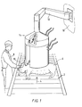
- Fig. 1 shows a section of a slaughterhouse, in which stunned pigs 6 lying on their sides are transported to a sticking station on a conveyor belt 2, which advances in the direction of arrow 4.
- a sticking station In Fig. 1, only one pig 6 is shown; in practice, pigs 6 lie at such a short distance apart on the conveyor belt 2 that another pig 6 arrives at the sticking station every four seconds.
- the sticking station there is a sticker 8 holding a knife 10 for sticking the pig 6 in the carotid artery. The pig 6 bleeds to death through the cut 12 created in this way.
- a turret device 14 is suspended above the conveyor belt 2 and above the pigs 6, within easy reach of the sticker 8. For sticking each pig 6, the sticker 8 takes a knife out of the turret device 14, sticks the pig and places the knife 10 back in the turret device 14.
- the structure of the knife 10 and the turret device 14 will be explained in more detail below.
- the turret device 14 is suspended from a wall 18 of the slaughterhouse by means of a pivot arm 16, so that the sticker 8 can select the position of the turret device 14 in such a manner that knives can be taken out of and replaced in the turret device 14 as easily and quickly as possible.
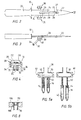
- Figs. 2-4 show the knife 10 in more detail.
- the knife 10 comprises a handle 20 and a blade 22, in which there is formed a recess 24 which extends in the longitudinal direction of the blade.
- Four projections 26 protrude inwards into the recess 24.
- a section of a tube 28 which is open on the side of the point of the blade 22.
- the tube 28 is coupled to and in liquid communication with a buffer chamber 30, which in turn is coupled to and in liquid communication with two buffer chamber outlets 32, which are in the form of tube stubs and have an annular seal 34 at their free end.
- Sample reservoirs 36 made of a transparent material are pushed around the buffer chamber outlets 32.
- the seals 34 hold the sample reservoirs 36 fixed to the buffer chamber outlets 32.
- the buffer chamber 30, which in the embodiment shown is substantially cylindrical, tapers conically on the outside towards both ends and ends in the form of a rectangle with a square cross-section.
- the partially conical, partially rectangular projections 38 are each provided with an opening 40, via which the interior of the buffer chamber 30 is in open communication with the atmosphere.
- Figs. 5a and 5b diagrammatically clarify the function of the buffer chamber 30 and the sample reservoirs 36.
- the blade 22 of the knife 10 When the blade 22 of the knife 10 is stuck into a blood vessel of an animal to be slaughtered, blood flows via the opening 27, through the tube 28 and into the buffer chamber 30, the openings 40 acting as vent and overflow openings. A level of blood 42 which is shown in Fig. 5a is thus established in the buffer chamber 30. If the sample reservoirs 36 are then moved away from the buffer chambers outlets 32, the seal 34 ensures that the blood 42 from the buffer chamber 30 is drawn into the sample reservoirs 36, the openings 40 serving the purpose of aeration, as illustrated in Fig. 5b. The quantity of blood 42 in the buffer chamber 30 as shown in Fig. 5a is distributed evenly between the two sample reservoirs 36, as shown in Fig. 5b.
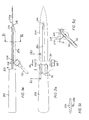
- Figs. 2a, 3a, 5c and 5d show a knife 200 with a handle 202 and a blade 204. On one side of the blade 204, a hollow tube 28a is arranged substantially parallel to the longitudinal direction of the blade 204.
- the tube 28a in Figs. 2a, 3a, 5c and 5d is connected to a buffer chamber 30 which is provided with partially frustoconical and partially rectangular projections 38.
- Two buffer chamber outlets 32 can be provided with sample reservoirs 36, as shown in particular in Fig. 5d.
- the buffer chamber 30 is provided with a support 206 with a hole which is provided with an internal screw thread.
- the blade 204 is provided with a through-hole.
- the support 206 can thus be attached to the blade 204 by means of a screw 208, with the result that the tube 28a, the buffer chamber 30 with projections 38 and the buffer chamber outlets 32 are fixed in position with respect to the blade 204.
- the latter is provided at its free end with a lip 210 which is accommodated in a hole 210a in the blade 204.
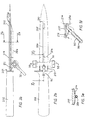
- Figs. 2b, 3b, 5e and 5f show a knife 201 with a handle 202 and a blade 205.
- the knife 201 differs only slightly from the knife 200 which is shown in Fig. 2a, 3a, 5c and 5d.
- the knife 201 is provided with two circlips 212 and 214, which interact with the lip 210 so as to fix the blood sampling section of the knife 201 in position with respect to the blade 205.
- the circlip 214 clamps around the blade 205, while the spring 212 ensures that the lip 210 is fixed in the opening 210a.
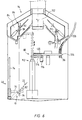
- Figs. 6 and 7 show the turret device 14 in which the knife 10 can be placed after sticking, and in which the sample reservoirs 36 are removed from the knife, sealed and removed, and the knife 10 is cleaned, disinfected and provided with new sample reservoirs 36, after which the knife is presented again to the sticker.
- the turret device 14 comprises a knife-holding station 46, a number of cleaning and disinfection stations 48, 50, 52, 54, 56, 58 and 60, a sample reservoir removal station 62, a sample reservoir attachment station 64, a knife delivery station 66, and transportation means for transporting the knife past the various stations. Furthermore, the turret device 14 comprises sample reservoir transportation means 68 for removing and feeding blood-filled and empty sample reservoirs.
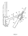
- the knife-holding station 46 will be described in more detail with reference to Figs. 6 and 9.
- the holding station 46 comprises an arm 70 which is attached to a so-called piston-rod-free cylinder 72, and as a result can be moved along a rod 74 in the directions of double arrow 76.
- the arm 70 bears a support device 78 which comprises two holding forks 80 with teeth of unequal length, the holding forks 80 being shaped and arranged in such a manner that the buffer chamber 30 can be held between their teeth.
- a support 82 for supporting the blade 22 of the knife 10.
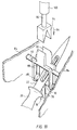
- the knife 10 is transported upwards towards a clamping device 86 which is disposed between plates 84.
- the clamping device 86 is attached between the plates 84 and comprises two clamping parts 88, the bottom ends of which can be moved apart in the manner of a clothes peg and are provided with rectangular recesses for accommodating the rectangular part of the projections 38 on the buffer chamber 30 in a substantially form-fitting manner.
- the clamping parts 88 pivot, under the opposing force of a spring (not shown in more detail), around rod 92, during the course of which pivoting the projections 38 of the knife 10 can be accommodated but also released again.
- the protrusions 90 can be moved towards one another, for example, by moving a block 94 with a V-shaped recess over the protrusions 90, in the direction of arrow 96.
- the block 94 can be driven in a manner which is not shown in more detail by means of a piston rod 98 of a piston-cylinder unit 100.
- the knife In the clamping device 86, between the plates 84, the knife is moved through the abovementioned stations by means of a displacement of this unit through predetermined angles by means of an indexed movement of the plates 84 and the clamping device 86 using a vertical shaft 102 to which the plates 84 are attached.
- the shaft 102 is provided along its entire circumference with plates 84 which are arranged at regular angular distances and have clamping devices 86 arranged between them, so that knives 10 can be received continuously, can be guided in steps through the various stations and can be delivered again.
- the turret device 14 depicted in Fig. 6 and 7 contains sixteen plates 84 and the same number of clamping devices 86.
- the knife delivery station 66 in principle contains the same components as the knife-holding station 46, but works in the opposite way: by opening the clamping parts 88, the knife 10 which is held in the clamping device 86 is lowered into the fork parts 80 of the support device 78, which for this purpose has been placed directly beneath the clamping device 86. Then, the arm 70 together with the knife 10 in the support device 78 is moved downwards along the rod 74, after which the sticker can take the knife 10 out of the holding forks 80.
- the outside of the knife 10 is sprayed with cold water for the purpose of removing blood residues. Details of spraying means are not shown here, since the person skilled in the art can design these based on his/her own experience.
- the knife 10 is then blow-dried in a manner not shown in more detail in the cleaning station 48 with the aid of compressed air.
- the sample reservoir removal station 62 the sample reservoirs are removed from the knife 10 in a manner which will be discussed in more detail below.
- the inside of the knife 10 is then cleaned in the cleaning station 50 using cold water, for example by spraying water, via a suitable nozzle 104 which is placed mechanically on the buffer chamber outlets, through the buffer chamber outlets 32, the buffer chamber 30 and the tube 28. This is illustrated diagrammatically in Fig.
- the outside of the knife 10 is then cleaned with cold water in a manner which is not shown in more detail.
- the inside of the knife is then disinfected in the disinfection station 54 using hot water at a temperature of about 82°C, for example with the aid of a similar nozzle to the nozzle 104 which is shown in Fig. 6.
- the outside of the knife 10 is then disinfected in the disinfection station 56 using hot water at a temperature of about 82°C.
- the knife 10 is rinsed with cold water in the cleaning station 58 and is blow-dried with compressed air in the cleaning station 60.
- new sample reservoirs are attached to the buffer chamber outlets 32 in a manner which will be discussed in more detail below.
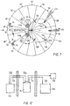
- the sample reservoir transportation means 68 which comprise an indexed disc 106 which can be rotated in a horizontal plane through predetermined angles and in which sets of openings 108, the pitch of which in the radial direction corresponds to the pitch of the buffer chamber outlets 32 of the knife 10, are arranged at angular distances of 60°.
- the openings 108 are shown in more detail in Fig. 8, which also shows a sample reservoir 36 which is provided with a cap 110. The sample reservoir 36 is suspended from the cap 110 in the opening 108 which has two different diameters.
- transverse arms 114a and 114b are arranged on two telescopically extendable arms 112a and 112b, which transverse arms 114a and 114b can pivot about the telescopic arms and are each provided at their free ends with a clamping device 116, which is not shown in more detail and in which two sample reservoirs 36 can be clamped.
- the arm 112a is extended to a suitable length and the transverse arm 114a is moved into the position indicated by dashed lines in Fig. 7.
- the sample reservoirs 36 situated on the knife 10 are then gripped by the associated clamping device 116 and are pulled off the buffer chamber outlets 32 by retracting the arm 112a.
- the transverse arm 114a can then be pivoted beneath the disc 106, the blood-filled sample reservoirs moving into the position indicated in Fig. 7 by 118.
- new, empty sample reservoirs which are provided with small caps, are placed in the vacant openings 108 by supplying these reservoirs through hoses 126 with the aid of compressed air.
- the new sample reservoirs are gripped by the clamping device 116, which is arranged on the transverse arm 114b, at the location indicated by 128 and, by means of sliding movements of the arm 112b and a pivoting movement of transverse arm 114b, they are moved towards and arranged on a cleaned knife 10.
- the small caps 110 of the empty sample reservoirs 36 remain behind at position 128, and these small caps 110 are used in the position of the disc 106 which is indicated by 118 to close off other blood-filled sample reservoirs 36.
- the small cap 110 On the side remote from the sample tube 36, the small cap 110 may be provided with a machine-readable code, which, for example in the position of the disc 106 indicated by 130, can be read with the aid of a sensor 131 which is arranged above the disc 106 and is merely indicated by dashed lines.
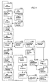
- Fig. 11 shows the actions carried out in the turret device 14 and other actions associated with the blood sampling, in the logical order indicated by arrows.
- the knife 10 is moved to the knife delivery station 66.
- the knife is then presented to the sticker, as indicated by step 142.
- the sticker takes hold of the knife, after which, in step 146, the animal for slaughtering is stuck and a blood sample is left in the knife.
- the sticker then places the knife 10 back in the turret device 14, into the knife-holding station 46.
- the knife 10 is discharged from the knife-holding station 46 into the cleaning station 48.
- step 150 the outside of the knife is cleaned with cold water in the cleaning station 48 and then, in step 154, it is blow-dried using compressed air. If appropriate, step 154 can be missed out, as indicated by a dashed line. Then, in step 156, which is carried out in the sample reservoir removal station 62, the sample reservoirs 36 are removed from the knife.
- step 158 The inside of the remaining part of the knife is cleaned with cold water in step 158 in cleaning station 50, and then the outside is cleaned with cold water in step 160 in cleaning station 52, after which, in step 162, the inside is disinfected in disinfection station 54, then the outside is disinfected in step 164 in disinfection station 56, then in step 166 the knife is rinsed with cold water in cleaning station 58 and finally blow-dried in step 168 using compressed air in cleaning station 60. Then, in step 170, new sample reservoirs are placed on the knife in sample reservoir attachment stations 64. The knife is now ready to be used again, so that step 140 can then follow. After step 156, comprising the removal of the reservoirs from the knife, in step 172 the reservoirs are sealed at the location indicated in Fig.
- step 174 The reservoirs are subsequently discharged in step 174, one sample reservoir being discharged to an analysis device and the other sample reservoir being temporarily stored.
- step 176 the said one blood sample is analyzed, after which, in step 178, the analysis results are stored in a data file.
- step 180 an identifying mark provided on the sample reservoirs is read and in step 182 a classification mark of the slaughter animal is read.
- step 184 data relating to the identifying mark and the classification mark are stored in a data file. This data is coupled with the results stored in step 178, as indicated by the dashed line between steps 184 and 178.
- step 170 which comprises placing the sample reservoirs on the knife
- step 186 an anti-coagulant is placed in each sample reservoir, and in step 188 the sample reservoirs are transported towards the turret device 14, in particular the rotatable disc 106.
- FIG. 12 illustrates the position of various components of the sampling system according to the invention.
- a sample reservoir feed device 192 is disposed in a room 190, from where new, empty sample reservoirs, which are provided with a cap, are fed via the hoses 126 to the turret device 14.
- the turret device is situated in a room 194 which is separated from the room 190.
- blood-filled sample reservoirs 36 which are provided with a cap are discharged, via the hoses 124, to a storage device 196 and an analysis device 198.
- the latter two devices 196 and 198 are situated in a room 196 which is separate from the room 194.
- the rooms 190 and 196 may if desired coincide. Separating the room 194 from the rooms 190 and 196 assists with the hygiene of the blood sampling.
Landscapes
- Health & Medical Sciences (AREA)
- General Health & Medical Sciences (AREA)
- Life Sciences & Earth Sciences (AREA)
- Public Health (AREA)
- Epidemiology (AREA)
- General Chemical & Material Sciences (AREA)
- Animal Behavior & Ethology (AREA)
- Chemical Kinetics & Catalysis (AREA)
- Chemical & Material Sciences (AREA)
- Veterinary Medicine (AREA)
- Hematology (AREA)
- Engineering & Computer Science (AREA)
- Food Science & Technology (AREA)
- Investigating Or Analysing Biological Materials (AREA)
- Automatic Analysis And Handling Materials Therefor (AREA)
- Sampling And Sample Adjustment (AREA)
Abstract
Description
- The invention relates to a method for taking a blood sample of an individual slaughter animal, such as a pig, cow, sheep or the like, according to the preamble of claim 1.
- It is usual to sample the blood of animals destined for slaughter at the farm where they are reared. The blood sample obtained in this way, which can be traced back unequivocally to a specific animal by means of an earmark identification on the animals, is analyzed in a laboratory for abnormalities which could lead to the possibility of taking measures to withdraw the animal in question from slaughter and consumption or even to the rejection of all the livestock present at the farm for slaughter and consumption.
- Although blood sampling is a necessary action for protecting public health, the operation of taking the blood samples at the farm is laborious, time-consuming and expensive, since to do this experts have to visit many farms every day and have to take and store blood samples by hand, blood samples have to be transported specially and extensive administration is required.
- The object of the invention is to simplify considerably the blood sampling of slaughter animals and the administration thereof and to shorten drastically the time required for this purpose. Another object of the invention is to provide a method and device which enable the blood sampling to be mechanized.
- The above objects, and other objects, are achieved using the method according to the invention as defined in claim 1. Sticking the slaughter animal is the action in the slaughterhouse in which a blood vessel of a slaughter animal, which has been stunned beforehand, is cut using a knife, so that the slaughter animal bleeds to death, as disclosed in WO-A-90/14013. At the moment of sticking, a sample of the stream of blood released can be taken easily and without loss of time.
- Each sample reservoir, which only has to be able to contain a very small quantity of blood, forms a unit with the knife, which as a result can be handled in the conventional way by a sticker in a slaughterhouse for sticking an animal for slaughtering.
- If the blood sample is collected in two different sample reservoirs which are coupled to the knife, one of these sample reservoirs can be analyzed while the other sample reservoir, which contains blood from the same slaughter animal as the first sample reservoir, can be stored for a possible second opinion.
- In a simple and inexpensive embodiment of the method according to the invention, after detaching each blood-filled sample reservoir from the knife, the knife is cleaned and disinfected, and then (a) new sample reservoir(s) is/are coupled to the knife. By connecting the sample reservoir to the knife in a detachable manner, the knife, after taking a blood sample, can be quickly cleaned and made ready for sticking and taking a new blood sample from a subsequent slaughter animal. This also avoids cross-contamination of slaughter animals.
- Preferably, one sample reservoir, which has been filled with blood during the sticking of the slaughter animal, is sealed after it has been detached from the knife and is conveyed to a room which is situated in the slaughterhouse and where one or more predetermined analyses are carried out on the blood sample. In this way, the blood sample is transferred to a "clean" room in order to be analyzed, the risk of the blood sample becoming contaminated or infected being minimal. In addition, it is thus possible for the blood sample to be analyzed within a very short time, so that the analysis results are known even during the further slaughtering process of the slaughter animal from which the blood sample originates, and in particular before the slaughter animal is cooled in a cooling chamber. If the blood sample analysis shows that this is necessary, the slaughter animal can be removed from the slaughter line.
- A particularly inexpensive, simple and rapid way of transporting the sample reservoir takes place in a hose or tube with the aid of a fluid at superatmospheric pressure, such as compressed air, or at subatmospheric pressure.
- The cleaning and disinfection of the knife after each sample reservoir filled with blood has been detached expediently comprises the following steps: cleaning with cold water; disinfecting; flushing with cold water; and blow-drying. Cleaning with cold water removes blood residues. Disinfecting of the knife is carried out, for example, with water at about 82°C, but can also be carried out using cold or hot water to which a disinfectant has been added. The subsequent rinsing with cold water cools the knife and prevents the formation of a layer of protein on the knife. In an optional extra cleaning step, the knife is cleaned with cold water, and optionally blow-dried, before each sample reservoir filled with blood is detached, in order even at this stage to remove as much adhering blood as possible.
- In order to administer the blood sample data, each sample reservoir filled with blood is provided with a sample reservoir identifying mark which belongs to a slaughter animal identifying mark arranged on or in said slaughter animal from which the blood in the sample reservoir originates, the sample reservoir identifying mark and the slaughter animal identifying mark are each read by means of a suitable reading device, and data resulting from this reading are stored in combination in a data file, such as a computer memory. After analysis of the blood sample, data relating to the analysis results are added to the said data combination. An example of an identifying mark of a slaughter animal is an earmark or an implanted transponder. Other possible identifying marks are letters, numbers, symbols, patterns or the like, or combinations thereof, which are branded or pierced on parts of the body. A sample reservoir may be provided with a bar code or a dot code, or the like. The identifying marks can preferably be read by machine.
- Furthermore, it is preferred for an anti-coagulant to be introduced into each sample reservoir before use, so that it is mixed with the blood sample directly when the sample is taken.
- According to the invention, the knife for taking a blood sample of a slaughter animal is characterized according to claim 11.
- In a preferred embodiment, the duct opens out at the abovementioned other end into a buffer chamber with at least one outlet to the at least one sample reservoir. The buffer chamber is dimensioned in such a way that during the blood sampling it fills up at least in part with blood.
- To assist the flow of blood into the buffer chamber, the latter contains at least one opening to atmosphere. During the blood sampling, this opening functions as a vent for the buffer chamber. The abovementioned opening, or another opening to atmosphere, may serve as an overflow opening for determining a maximum blood level in the buffer chamber, so that the volume of blood collected in the buffer chamber during the blood sampling can be accurately predetermined.
- In a preferred embodiment, the buffer chamber outlet to a sample reservoir comprises a tube stub and the sample reservoir comprises a sample tube with a closed end and an opposite open end, it being possible to push the tube stub and the sample tube over one another, and the free end of the tube stub being connected in a sealing manner to the sample tube. Such a sealed design of the buffer chamber outlet and the sample reservoir ensures that blood is reliably drawn from the buffer chamber into the sample reservoir during the removal of the sample tube from the tube stub.
- Preferably, the knife blade is provided with a recess for accommodating at least part of a duct which is designed as a tube. In an embodiment of this kind, there is no need to produce a special knife, but rather it is possible to base the design on a standard, commercially available knife, and it is merely necessary to form a recess in the blade of such a knife.
- Advantageously, the duct is arranged detachably in the recess, so that the duct and the connected buffer chamber and buffer chamber outlet(s) can simply be detached from a knife which has become worn as a result of use and can be arranged in a new knife provided with a recess. In particular, the duct is adhesively bonded by means of a soluble or softenable adhesive to projections which protrude into the recess. On the other hand, it is possible, to allow quick and easy exchange of knives, to attach the buffer chamber to the blade using a screw or circlip fastening. In this case, the duct running along the blade is stabilized at its free end by providing it with a lip which projects into an associated opening in the blade.
- It is also pointed out that the buffer chamber outlets of the knife prevent the hand of the sticker sliding off the handle of the knife and over the blade, so that undesirable injuries are prevented.
- In order to achieve as high a level of mechanisation of the blood sampling as possible, the knife is provided with at least one projection for positioning the knife in a knife support which is at least partially of complementary form to the at least one projection. The at least one projection makes it possible to place the knife in the knife support in an unambiguous manner, after which it is possible for the actions comprising removal of the sample reservoir(s), cleaning of the knife and attachment of (a) new sample reservoirs) to take place completely mechanically and automatically.
- The knife is preferably provided with two projections which protrude in opposite directions, and part of each projection preferably has a substantially circular cross-section, another part of the projection having a substantially rectangular cross-section. This measure increases the stability of the knife in the knife support.
- Furthermore, for the benefit of mechanical and automatic execution of the actions described above, the invention provides a blood sample processing device for processing a blood sample of a slaughter animal, comprising: a knife-holding station for holding a knife according to the invention; a sample reservoir removal station for removing the sample reservoir(s) from the knife; at least one cleaning and/or disinfection station for cleaning and disinfecting the knife; a sample reservoir attachment station for attaching the sample reservoir(s) to the knife; a knife delivery station for delivering the knife; and knife transportation means for transporting the knife past the stations.
- In a preferred embodiment, the blood sample processing device comprises sample reservoir transportation means which comprise a clamping device, which is arranged on a movable arm for gripping at least one sample reservoir, as well as a rotatable disc, which is provided with openings, for holding the sample reservoir(s) and attaching/removing small caps thereto/ therefrom, and at least one hose or tube in which the sample reservoir(s) can be transported at superatmospheric pressure or subatmospheric pressure, the arm with clamping device transporting the sample reservoir(s) from the sample reservoir removal station to the disc, and the disc conveying the sample reservoir(s) from the arm with clamping device to the at least one hose or tube, or alternatively the transportation taking place in the opposite direction, from the at least one hose or tube to the sample reservoir attachment station. If one ensures that the small cap of the sample reservoir is unable to pass through the opening while the sample reservoir can pass thorough the opening, the sample reservoir can hang from the small cap in an opening in the disk when the latter is disposed horizontally. By pulling the sample reservoir downwards beneath the disk, the small cap is separated from the reservoir. If the small cap is supported at the top side of the disc, the sample reservoir can easily be pressed firmly onto the small cap through the opening, from the underside of the disk.
- Preferably, the knife-holding station comprises a movable knife support for supporting the knife for the purpose of feeding the knife to the knife transportation means in a predetermined position. After use, the sticker places his/her knife in the knife support, which determines the position of the knife and consequently allows the knife to be manipulated mechanically and automatically in the blood sample processing device.
- In an advantageous embodiment, the at least one cleaning and disinfection station comprises: a first station with a cold water feed device for cleaning the knife with cold water; a second station with a disinfectant feed device for disinfecting the knife, which disinfectant consists, for example, of water at about 82 °C or of a lactic acid solution or chlorine solution; a third station with a flushing device for rinsing the knife with cold water; and a fourth station with an air-blowing device for blow-drying the knife using air. Preferably, the first station and the second station are each designed for the internal and external cleaning of the knife.
- The knife delivery station works in the opposite way to the knife-holding station.
- In a preferred embodiment, the knife transportation means comprise a gripper device which engages on the knife for fixing the knife in a predetermined position during transportation of the knife past the stations, which gripper device can be moved between a closed position and an open position. The gripper device allows simple transfer of the knife from the movable knife support (in the knife-holding station) or to the movable knife support (in the knife delivery station).
- In a particularly compact and efficient embodiment of the blood sample processing device, the knife transportation means execute a circular movement, and the stations are disposed at predetermined angular positions along the circle.
- The invention is explained in more detail with reference to the drawing, in which:
- Fig. 1 shows a diagrammatic, perspective view of a device according to the invention;
- Fig. 2 shows a top view of a knife according to the invention;
- Fig. 2a shows a top view of another knife according to the invention;
- Fig. 2b shows a top view of yet another knife according to the invention;
- Fig. 3 shows a side view of the knife shown in Fig. 2;
- Fig. 3a shows a side view of the knife shown in Fig. 2a;
- Fig. 3b shows a side view of the knife shown in Fig. 2b;
- Fig. 4 shows a front view of the knife of Fig. 2 in the direction of arrow IV;
- Figs. 5a and 5b show a cross-sectional view of the action of sample reservoir(s) coupled to the knife;
- Fig. 5c shows a view of the cross-section of the knife on line Vc-Vc in Fig. 3a;
- Fig. 5d shows a partial longitudinal section through the knife on line Vd-Vd in Fig. 2a;
- Fig. 5e shows a view of the cross-section of the knife on line Ve-Ve in Fig. 3b;
- Fig. 5f shows a partial longitudinal section through the knife on line Vf-Vf in Fig. 2b;
- Fig. 6 shows, partially in cross-section and partially in side view, a turret device according to the invention;
- Fig. 7 shows a diagrammatic plan view of the device in accordance with Fig. 6;
- Fig. 8 shows a detail of the device shown in Fig. 6;
- Fig. 9 shows a perspective view of a detail of the device shown in Fig. 6;
- Fig. 10 shows a perspective view of another detail of the device shown in Fig. 6;
- Fig. 11 shows a flow diagram for the purpose of explaining the actions carried out in the device in accordance with Fig. 6; and
- Fig. 12 shows the layout of the device in accordance with Fig. 6 in a slaughterhouse.
-
- In the various figures, equivalent reference numerals relate to equivalent components or components which have an equivalent function.
- Fig. 1 shows a section of a slaughterhouse, in which stunned
pigs 6 lying on their sides are transported to a sticking station on aconveyor belt 2, which advances in the direction ofarrow 4. In Fig. 1, only onepig 6 is shown; in practice,pigs 6 lie at such a short distance apart on theconveyor belt 2 that anotherpig 6 arrives at the sticking station every four seconds. In the sticking station, there is a sticker 8 holding aknife 10 for sticking thepig 6 in the carotid artery. Thepig 6 bleeds to death through thecut 12 created in this way. - A
turret device 14 is suspended above theconveyor belt 2 and above thepigs 6, within easy reach of the sticker 8. For sticking eachpig 6, the sticker 8 takes a knife out of theturret device 14, sticks the pig and places theknife 10 back in theturret device 14. The structure of theknife 10 and theturret device 14 will be explained in more detail below. Theturret device 14 is suspended from awall 18 of the slaughterhouse by means of apivot arm 16, so that the sticker 8 can select the position of theturret device 14 in such a manner that knives can be taken out of and replaced in theturret device 14 as easily and quickly as possible. - Figs. 2-4 show the
knife 10 in more detail. Theknife 10 comprises ahandle 20 and ablade 22, in which there is formed a recess 24 which extends in the longitudinal direction of the blade. Fourprojections 26 protrude inwards into the recess 24. Between theprojections 26 there is detachably arranged, for example by snap-fitting or adhesive bonding, a section of atube 28 which is open on the side of the point of theblade 22. Thetube 28 is coupled to and in liquid communication with abuffer chamber 30, which in turn is coupled to and in liquid communication with twobuffer chamber outlets 32, which are in the form of tube stubs and have anannular seal 34 at their free end.Sample reservoirs 36 made of a transparent material are pushed around thebuffer chamber outlets 32. Theseals 34 hold thesample reservoirs 36 fixed to thebuffer chamber outlets 32. Thebuffer chamber 30, which in the embodiment shown is substantially cylindrical, tapers conically on the outside towards both ends and ends in the form of a rectangle with a square cross-section. The partially conical, partiallyrectangular projections 38 are each provided with anopening 40, via which the interior of thebuffer chamber 30 is in open communication with the atmosphere. - Figs. 5a and 5b diagrammatically clarify the function of the
buffer chamber 30 and thesample reservoirs 36. When theblade 22 of theknife 10 is stuck into a blood vessel of an animal to be slaughtered, blood flows via theopening 27, through thetube 28 and into thebuffer chamber 30, theopenings 40 acting as vent and overflow openings. A level ofblood 42 which is shown in Fig. 5a is thus established in thebuffer chamber 30. If thesample reservoirs 36 are then moved away from thebuffer chambers outlets 32, theseal 34 ensures that theblood 42 from thebuffer chamber 30 is drawn into thesample reservoirs 36, theopenings 40 serving the purpose of aeration, as illustrated in Fig. 5b. The quantity ofblood 42 in thebuffer chamber 30 as shown in Fig. 5a is distributed evenly between the twosample reservoirs 36, as shown in Fig. 5b. - Figs. 2a, 3a, 5c and 5d show a
knife 200 with ahandle 202 and ablade 204. On one side of theblade 204, ahollow tube 28a is arranged substantially parallel to the longitudinal direction of theblade 204. In accordance with the design shown in Fig. 2, 3 and 4, thetube 28a in Figs. 2a, 3a, 5c and 5d is connected to abuffer chamber 30 which is provided with partially frustoconical and partiallyrectangular projections 38. Twobuffer chamber outlets 32 can be provided withsample reservoirs 36, as shown in particular in Fig. 5d. Thebuffer chamber 30 is provided with asupport 206 with a hole which is provided with an internal screw thread. At the location where thesupport 206 touches theblade 204, theblade 204 is provided with a through-hole. Thesupport 206 can thus be attached to theblade 204 by means of ascrew 208, with the result that thetube 28a, thebuffer chamber 30 withprojections 38 and thebuffer chamber outlets 32 are fixed in position with respect to theblade 204. In order to prevent deformation of thetube 28a, the latter is provided at its free end with alip 210 which is accommodated in ahole 210a in theblade 204. - Figs. 2b, 3b, 5e and 5f show a
knife 201 with ahandle 202 and ablade 205. Theknife 201 differs only slightly from theknife 200 which is shown in Fig. 2a, 3a, 5c and 5d. Instead of thesupport 206, which is attached to theblade 204 using abolt 208, of theknife 200, theknife 201 is provided with twocirclips lip 210 so as to fix the blood sampling section of theknife 201 in position with respect to theblade 205. As shown in particular by Fig. 5e, thecirclip 214 clamps around theblade 205, while thespring 212 ensures that thelip 210 is fixed in theopening 210a. - Figs. 6 and 7 show the
turret device 14 in which theknife 10 can be placed after sticking, and in which thesample reservoirs 36 are removed from the knife, sealed and removed, and theknife 10 is cleaned, disinfected and provided withnew sample reservoirs 36, after which the knife is presented again to the sticker. - For this purpose, the
turret device 14 comprises a knife-holdingstation 46, a number of cleaning anddisinfection stations reservoir removal station 62, a samplereservoir attachment station 64, aknife delivery station 66, and transportation means for transporting the knife past the various stations. Furthermore, theturret device 14 comprises sample reservoir transportation means 68 for removing and feeding blood-filled and empty sample reservoirs. - The knife-holding
station 46 will be described in more detail with reference to Figs. 6 and 9. The holdingstation 46 comprises anarm 70 which is attached to a so-called piston-rod-free cylinder 72, and as a result can be moved along arod 74 in the directions ofdouble arrow 76. At the end remote from thecylinder 72, thearm 70 bears asupport device 78 which comprises two holdingforks 80 with teeth of unequal length, the holdingforks 80 being shaped and arranged in such a manner that thebuffer chamber 30 can be held between their teeth. As shown in Fig. 6, it is additionally possible to provide asupport 82 for supporting theblade 22 of theknife 10. - As illustrated in more detail in Figs. 6 and 10, in the holding
station 46 theknife 10 is transported upwards towards a clampingdevice 86 which is disposed betweenplates 84. The clampingdevice 86 is attached between theplates 84 and comprises two clampingparts 88, the bottom ends of which can be moved apart in the manner of a clothes peg and are provided with rectangular recesses for accommodating the rectangular part of theprojections 38 on thebuffer chamber 30 in a substantially form-fitting manner. By moving theprotrusions 90 of the clampingparts 88 towards one another, the clampingparts 88 pivot, under the opposing force of a spring (not shown in more detail), aroundrod 92, during the course of which pivoting theprojections 38 of theknife 10 can be accommodated but also released again. Theprotrusions 90 can be moved towards one another, for example, by moving ablock 94 with a V-shaped recess over theprotrusions 90, in the direction ofarrow 96. Theblock 94 can be driven in a manner which is not shown in more detail by means of apiston rod 98 of a piston-cylinder unit 100. In theclamping device 86, between theplates 84, the knife is moved through the abovementioned stations by means of a displacement of this unit through predetermined angles by means of an indexed movement of theplates 84 and theclamping device 86 using avertical shaft 102 to which theplates 84 are attached. Theshaft 102 is provided along its entire circumference withplates 84 which are arranged at regular angular distances and haveclamping devices 86 arranged between them, so thatknives 10 can be received continuously, can be guided in steps through the various stations and can be delivered again. Theturret device 14 depicted in Fig. 6 and 7 contains sixteenplates 84 and the same number ofclamping devices 86. - The
knife delivery station 66 in principle contains the same components as the knife-holdingstation 46, but works in the opposite way: by opening the clampingparts 88, theknife 10 which is held in theclamping device 86 is lowered into thefork parts 80 of thesupport device 78, which for this purpose has been placed directly beneath the clampingdevice 86. Then, thearm 70 together with theknife 10 in thesupport device 78 is moved downwards along therod 74, after which the sticker can take theknife 10 out of the holdingforks 80. - In the cleaning
station 48, the outside of theknife 10 is sprayed with cold water for the purpose of removing blood residues. Details of spraying means are not shown here, since the person skilled in the art can design these based on his/her own experience. Theknife 10 is then blow-dried in a manner not shown in more detail in the cleaningstation 48 with the aid of compressed air. In the samplereservoir removal station 62, the sample reservoirs are removed from theknife 10 in a manner which will be discussed in more detail below. The inside of theknife 10 is then cleaned in the cleaningstation 50 using cold water, for example by spraying water, via asuitable nozzle 104 which is placed mechanically on the buffer chamber outlets, through thebuffer chamber outlets 32, thebuffer chamber 30 and thetube 28. This is illustrated diagrammatically in Fig. 6 in an angular position which, for the sake of clarity, differs from the angular position shown for the cleaningstation 50 in Fig. 7. In the cleaningstation 52, the outside of theknife 10 is then cleaned with cold water in a manner which is not shown in more detail. The inside of the knife is then disinfected in thedisinfection station 54 using hot water at a temperature of about 82°C, for example with the aid of a similar nozzle to thenozzle 104 which is shown in Fig. 6. The outside of theknife 10 is then disinfected in thedisinfection station 56 using hot water at a temperature of about 82°C. Finally, in a manner which is not shown in more detail, theknife 10 is rinsed with cold water in the cleaningstation 58 and is blow-dried with compressed air in the cleaningstation 60. When theknife 10 has arrived in the samplereservoir attachment station 64, new sample reservoirs are attached to thebuffer chamber outlets 32 in a manner which will be discussed in more detail below. - In the
turret device 14, there are arranged the sample reservoir transportation means 68, which comprise an indexeddisc 106 which can be rotated in a horizontal plane through predetermined angles and in which sets ofopenings 108, the pitch of which in the radial direction corresponds to the pitch of thebuffer chamber outlets 32 of theknife 10, are arranged at angular distances of 60°. Theopenings 108 are shown in more detail in Fig. 8, which also shows asample reservoir 36 which is provided with acap 110. Thesample reservoir 36 is suspended from thecap 110 in theopening 108 which has two different diameters. In theturret device 14,transverse arms extendable arms arms clamping device 116, which is not shown in more detail and in which twosample reservoirs 36 can be clamped. - As shown diagrammatically in Figs. 6 and 7, when the knife is situated in the sample
reservoir removal station 62, thearm 112a is extended to a suitable length and thetransverse arm 114a is moved into the position indicated by dashed lines in Fig. 7. Thesample reservoirs 36 situated on theknife 10 are then gripped by the associatedclamping device 116 and are pulled off thebuffer chamber outlets 32 by retracting thearm 112a. Thetransverse arm 114a can then be pivoted beneath thedisc 106, the blood-filled sample reservoirs moving into the position indicated in Fig. 7 by 118. Those ends of thesample reservoirs 36 which protrude above thetransverse arm 114a and theclamping device 116 are then moved into the associatedopenings 108 in thedisc 106 by extending thearm 112a, during which operation thesample reservoirs 36 are simultaneously sealed by acap 110 which is already situated in theopening 108 and is held inposition 118 above thedisc 106 by means of astop 120. After thedisc 106 has been rotated through 60° in the direction ofarrow 122, the blood-filled and sealedsample reservoirs 36 are drawn intohoses 124 and removed with the aid of subatmospheric pressure. When thedisc 106 has again been rotated through 60° in thedirection 122, new, empty sample reservoirs, which are provided with small caps, are placed in thevacant openings 108 by supplying these reservoirs throughhoses 126 with the aid of compressed air. After being rotated through a further 120°, the new sample reservoirs are gripped by theclamping device 116, which is arranged on thetransverse arm 114b, at the location indicated by 128 and, by means of sliding movements of thearm 112b and a pivoting movement oftransverse arm 114b, they are moved towards and arranged on a cleanedknife 10. Thesmall caps 110 of theempty sample reservoirs 36 remain behind atposition 128, and thesesmall caps 110 are used in the position of thedisc 106 which is indicated by 118 to close off other blood-filledsample reservoirs 36. - On the side remote from the
sample tube 36, thesmall cap 110 may be provided with a machine-readable code, which, for example in the position of thedisc 106 indicated by 130, can be read with the aid of asensor 131 which is arranged above thedisc 106 and is merely indicated by dashed lines. - Fig. 11 shows the actions carried out in the
turret device 14 and other actions associated with the blood sampling, in the logical order indicated by arrows. Instep 140, theknife 10 is moved to theknife delivery station 66. In theknife delivery station 66, the knife is then presented to the sticker, as indicated bystep 142. Instep 144, the sticker takes hold of the knife, after which, instep 146, the animal for slaughtering is stuck and a blood sample is left in the knife. Instep 148, the sticker then places theknife 10 back in theturret device 14, into the knife-holdingstation 46. Instep 150, theknife 10 is discharged from the knife-holdingstation 46 into the cleaningstation 48. If, afterstep 142, the sticker does not take hold of the knife, the unused knife is removed instep 150. Instep 152, the outside of the knife is cleaned with cold water in the cleaningstation 48 and then, instep 154, it is blow-dried using compressed air. If appropriate, step 154 can be missed out, as indicated by a dashed line. Then, instep 156, which is carried out in the samplereservoir removal station 62, thesample reservoirs 36 are removed from the knife. The inside of the remaining part of the knife is cleaned with cold water instep 158 in cleaningstation 50, and then the outside is cleaned with cold water in step 160 in cleaningstation 52, after which, instep 162, the inside is disinfected indisinfection station 54, then the outside is disinfected instep 164 indisinfection station 56, then instep 166 the knife is rinsed with cold water in cleaningstation 58 and finally blow-dried instep 168 using compressed air in cleaningstation 60. Then, instep 170, new sample reservoirs are placed on the knife in samplereservoir attachment stations 64. The knife is now ready to be used again, so thatstep 140 can then follow. Afterstep 156, comprising the removal of the reservoirs from the knife, instep 172 the reservoirs are sealed at the location indicated in Fig. 7 by 118. The reservoirs are subsequently discharged instep 174, one sample reservoir being discharged to an analysis device and the other sample reservoir being temporarily stored. Instep 176, the said one blood sample is analyzed, after which, instep 178, the analysis results are stored in a data file. In addition, instep 180, an identifying mark provided on the sample reservoirs is read and in step 182 a classification mark of the slaughter animal is read. Instep 184, data relating to the identifying mark and the classification mark are stored in a data file. This data is coupled with the results stored instep 178, as indicated by the dashed line betweensteps - Prior to step 170, which comprises placing the sample reservoirs on the knife, in a
step 186 an anti-coagulant is placed in each sample reservoir, and instep 188 the sample reservoirs are transported towards theturret device 14, in particular therotatable disc 106. - Fig. 12 illustrates the position of various components of the sampling system according to the invention. A sample
reservoir feed device 192 is disposed in aroom 190, from where new, empty sample reservoirs, which are provided with a cap, are fed via thehoses 126 to theturret device 14. The turret device is situated in aroom 194 which is separated from theroom 190. From theturret device 14, blood-filledsample reservoirs 36 which are provided with a cap are discharged, via thehoses 124, to astorage device 196 and ananalysis device 198. The latter twodevices room 196 which is separate from theroom 194. Therooms room 194 from therooms
Claims (34)
- Method for processing blood of an individual slaughter animal, comprising the steps of:characterized in that the blood sample (42) is taken during sticking of the slaughter animal (6) in a slaughterhouse at the sticking place (12) in the slaughter animal, and that the blood sample (42) is collected in at least one sample reservoir (36) which is coupled to, and movable with a knife (10) used for the sticking, whereafter the at least one sample reservoir (36) is detached from the knife (10) for analyzing the blood sample.cutting a blood vessel of the slaughter animal so as to release blood;taking a blood sample (42) from the blood released;analyzing the blood sample,
- Method according to claim 1, characterized in that the blood sample (42) is collected in two different sample reservoirs (36) which are coupled to the knife (10).
- Method according to claim 1 or 2, characterized in that after detaching each blood-filled sample reservoir (36) from the knife (10), the knife (10) is cleaned and disinfected, and then (a) new sample reservoir(s) (36) is/are coupled to the knife.
- Method according to claim 3, characterized in that one sample reservoir (36), which has been filled with blood during the sticking of the slaughter animal (6), is sealed after it has been detached from the knife (10) and is conveyed to a room (196) which is situated in the slaughterhouse and where one or more predetermined analyses are carried out on the blood sample (42).
- Method according to claim 4, characterized in that the sample reservoir (36) is conveyed in a hose (124) or tube with the aid of a fluid which is at superatmospheric or subatmospheric pressure.
- Method according to any of claims 3 - 5, characterized in that the cleaning and disinfection of the knife (10) after each sample reservoir (36) filled with blood (42) has been detached comprises the following steps:cleaning with cold water;disinfecting, in particular with water at 82 °C;flushing with cold water; andblow-drying.
- Method according to claim 6, characterized in that the knife (10) is cleaned with cold water, and optionally blow-dried, before each sample reservoir (36) filled with blood (42) is detached.
- Method according to any of claims 1 - 7, characterized in that each sample reservoir (36) filled with blood (42) is provided with a sample reservoir identifying mark which belongs to a slaughter animal identifying mark arranged on or in said slaughter animal (6) from which the blood in the sample reservoir originates, the sample reservoir identifying mark and the slaughter animal identifying mark are each read using a reading device (131), and data resulting from this reading are stored in combination in a data file.
- Method according to claim 8, characterized in that, after analysis of the blood sample (42), data relating to the analysis results are added to the said data combination.
- Method according to any of claims 1 - 9, characterized in that an anti-coagulant is introduced into each sample reservoir (36) prior to use.
- Knife provided with a duct (28) with an open end (27) in the region of the knife blade (22) which is intended to penetrate into a slaughter animal (6) for sticking the slaughter animal, which duct (28) is in liquid communication, at the other end, with at least one sample reservoir (36) which is coupled to, and movable with the knife, the at least one sample reservoir (36) being detachably connected to the knife (10) and being adapted to contain the blood of an individual slaughter animal.
- Knife according to claim 11, characterized in that the duct (28) opens out at said other end into a buffer chamber (30) with at least one outlet to the at least one sample reservoir (36).
- Knife according to claim 12, characterized in that the buffer chamber (30) is provided with at least one opening (40) to atmosphere for venting and aerating the buffer chamber.
- Knife according to claim 12 or 13, characterized in that the buffer chamber (30) is provided with at least one opening (40) to atmosphere for determining a maximum blood level in the buffer chamber.
- Knife according to any of claims 12 - 14, characterized in that the buffer chamber outlet comprises a tube stub (32) and in that the sample reservoir (36) comprises a sample tube with a closed end and an opposite open end, it being possible to push the tube stub and the sample tube over one another, and the free end of the tube stub being connected in a sealing manner (34) to the sample tube.
- Knife according to any of claims 11 - 15, characterized in that the knife blade (22) is provided with a recess (24) for accommodating at least part of a duct which is designed as a tube (28).
- Knife according to claim 16, characterized in that the duct (28) is arranged detachably in the recess (24).
- Knife according to claim 17, characterized in that the duct (28) is adhesively bonded to projections (26) which protrude into the recess (24).
- Knife according to any of claims 11 - 15, characterized in that the knife blade (204; 205) is provided with a hole (210) for accommodating one end of the duct (28a).
- Knife according to any of claims 11 - 15 or 19, characterized in that the buffer chamber (30) is attached to the knife blade (204; 205).
- Knife according to claim 20, characterized in that the attachment is formed by a screw fastening.
- Knife according to claim 20, characterized in that the attachment is formed by a circlip fastening (212, 214).
- Knife according to any of claims 11 - 22, characterized by at least one projection (38) for positioning the knife (10) in a knife support (80; 88) which is of at least partially complementary form to the at least one projection.
- Knife according to claim 23, characterized by two projections (38) which protrude in opposite directions.
- Knife according to claim 23 or 24, characterized in that part of each projection (38) has a substantially circular cross-section, and in that another part of the projection has a substantially rectangular cross-section.
- Blood sample processing device (14) for processing a blood sample (42) of a slaughter animal (6), comprising:a knife-holding station (46) for holding a knife (10) according to any of claims 11 - 25;a sample reservoir removal station (62) for removing the sample reservoir(s) (36) from the knife (10);at least one cleaning and/or disinfection station (48, 50, 52, 54, 56, 58, 60) for cleaning and disinfecting the knife (10);a sample reservoir attachment station (64) for attaching the sample reservoir(s) (36) to the knife (10);a knife delivery station (66) for delivering the knife (10); andknife transportation means for transporting the knife (10) past the stations.
- Blood sample processing device according to claim 26, characterized by sample reservoir transportation means which comprise a clamping device (116), which is arranged on a movable arm (112, 114) for gripping at least one sample reservoir (36), as well as a rotatable disc (106), which is provided with openings, for holding the sample reservoir(s) (36) and attaching/removing small caps (110) thereto/therefrom, and at least one hose (124, 126) or tube in which the sample reservoir(s) (36) can be transported at superatmospheric pressure or subatmospheric pressure, the arm (112, 114) with clamping device (116) transporting the sample reservoir(s) (36) from the sample reservoir removal station (62) to the disc (106), and the disc (106) conveying the sample reservoir(s) (36) from the arm (112, 114) with clamping device (116) to the at least one hose (124) or tube, or alternatively the transportation taking place in the opposite direction, from the at least one hose (126) or tube to the sample reservoir attachment station (64).
- Blood sample processing device according to claim 27, characterized in that the small cap (110) has dimensions which are such that it is unable to pass through the openings (108) in the disk (106), while the sample reservoir (36) has dimensions which are such that it can pass through the openings (108) in the disk (106).
- Blood sample processing device according to any of claims 26 - 28, characterized in that the knife-holding station (46) comprises a movable knife support (70, 72, 74, 78, 80) for supporting the knife (10) for the purpose of feeding the knife (10) to the knife transportation means in a predetermined position.
- Blood sample processing device according to any of claims 26 - 29, characterized in that the at least one cleaning and disinfection station comprises:a first station (50, 52) with a cold water feed device for cleaning the knife 910) with cold water;a second station (54, 56) with a disinfectant feed device for disinfecting the knife (10);a third station (58) with a flushing device for rinsing the knife (10) with cold water; anda fourth station (60) with an air-blowing device for blow-drying the knife (10) using air.
- Blood sample processing device according to claim 30, characterized in that the first station (50, 52) and the second station (54, 56) are each designed for the internal and external cleaning/disinfection of the knife (10).
- Blood sample processing device according to any of claims 26 - 31, characterized in that the knife delivery station (66) comprises a movable knife support (70, 72, 74, 78, 80) for supporting the knife (10) for the purpose of removing the knife (10) from the knife transportation means in a predetermined position.
- Blood sample processing device according to any of claims 26 - 32, characterized in that the knife transportation means comprise a gripper device (86) which engages on the knife (10) for fixing the knife (10) in a predetermined position during transportation of the knife (10) past the stations, which gripper device (86) can be moved between a closed position and an open position.
- Blood sample processing device according to any of claims 26 - 33, characterized in that the knife transportation means execute a circular movement, and in that the stations are disposed at predetermined angular positions along the circle.
Applications Claiming Priority (2)
| Application Number | Priority Date | Filing Date | Title |
|---|---|---|---|
| NL1005157A NL1005157C2 (en) | 1997-01-31 | 1997-01-31 | Method and device for taking a blood sample from a slaughtered animal. |
| NL1005157 | 1997-01-31 |
Publications (2)
| Publication Number | Publication Date |
|---|---|
| EP0861594A1 EP0861594A1 (en) | 1998-09-02 |
| EP0861594B1 true EP0861594B1 (en) | 2001-04-11 |
Family
ID=19764326
Family Applications (1)
| Application Number | Title | Priority Date | Filing Date |
|---|---|---|---|
| EP98200253A Expired - Lifetime EP0861594B1 (en) | 1997-01-31 | 1998-01-28 | Method and device for taking a blood sample of a slaughtered animal. |
Country Status (6)
| Country | Link |
|---|---|
| EP (1) | EP0861594B1 (en) |
| AT (1) | ATE200387T1 (en) |
| DE (1) | DE69800674T2 (en) |
| DK (1) | DK0861594T3 (en) |
| ES (1) | ES2159420T3 (en) |
| NL (1) | NL1005157C2 (en) |
Families Citing this family (6)
| Publication number | Priority date | Publication date | Assignee | Title |
|---|---|---|---|---|
| DK177335B1 (en) * | 2003-07-11 | 2013-01-21 | Teknologisk Inst | Device and method of sterilization |
| FR2867990A1 (en) * | 2004-03-29 | 2005-09-30 | Alain Rene Giraud | Automatic cleaning and asepticising procedure for rotary cutters used for removing spinal tissue from cattle carcases includes antiseptic fluid injection stage |
| DE102014002672B4 (en) | 2014-02-28 | 2015-10-08 | Prionics Ag | Method and means of marking slaughtered animals |
| CA3032966C (en) * | 2016-08-03 | 2020-09-08 | Mpsc Australia, Pty., Ltd | High speed rinsing solution application |
| CN109430350A (en) * | 2018-11-28 | 2019-03-08 | 孙全庆 | A kind of hygienic environment-protecting knife killing pig |
| CN119424704B (en) * | 2025-01-03 | 2025-03-28 | 核工业四一六医院 | A blood processing device for hematology |
Family Cites Families (1)
| Publication number | Priority date | Publication date | Assignee | Title |
|---|---|---|---|---|
| WO1990014013A1 (en) * | 1989-05-22 | 1990-11-29 | Anitec - John Sjöberg Ab | Device for withdrawing blood from slaughter animals |
-
1997
- 1997-01-31 NL NL1005157A patent/NL1005157C2/en not_active IP Right Cessation
-
1998
- 1998-01-28 DE DE69800674T patent/DE69800674T2/en not_active Expired - Fee Related
- 1998-01-28 DK DK98200253T patent/DK0861594T3/en active
- 1998-01-28 EP EP98200253A patent/EP0861594B1/en not_active Expired - Lifetime
- 1998-01-28 AT AT98200253T patent/ATE200387T1/en not_active IP Right Cessation
- 1998-01-28 ES ES98200253T patent/ES2159420T3/en not_active Expired - Lifetime
Also Published As
| Publication number | Publication date |
|---|---|
| ATE200387T1 (en) | 2001-04-15 |
| DK0861594T3 (en) | 2001-08-13 |
| DE69800674T2 (en) | 2003-08-07 |
| DE69800674D1 (en) | 2001-05-17 |
| EP0861594A1 (en) | 1998-09-02 |
| NL1005157C2 (en) | 1998-08-03 |
| ES2159420T3 (en) | 2001-10-01 |
Similar Documents
| Publication | Publication Date | Title |
|---|---|---|
| AU2019384619B2 (en) | Method and device for positioning and/or handling carcasses and/or carcass parts during the slaughter of animals on an industrial scale | |
| US6688255B2 (en) | Robotic apparatus and methods for maintaining stocks of small organisms | |
| KR20110099002A (en) | Apparatus for collecting animal tissue, and sets comprising same | |
| ATE275818T1 (en) | METHOD AND DEVICE FOR CLEANING TEATCUPS | |
| EP1222858B1 (en) | Method and device for processing a cluster of organs of a slaughtered animal | |
| EP0861594A1 (en) | Method and device for taking a blood sample of a slaughtered animal. | |
| EP3278670A1 (en) | Device for cleaning and for processing the rectum and pelvis of slaughtered pigs and operating method of said device | |
| US6685550B2 (en) | System and method for cleaning intestines | |
| CN109952509A (en) | Egg inspection and repositioning equipment for in ovo injection machines | |
| EP1115292A1 (en) | System for disinfection and method | |
| HU187060B (en) | Method and device for hygienic taking and collecting edible and inedible animal blood | |
| US12284978B2 (en) | Milking system with detection system | |
| ES et al. | Verfahren und Vorrichtung zur Abnahme einer Blutprobe von einem Schlachttierkörper Procédé et dispositif de prélèvement d’un échantillon de sang d’un animal abattu | |
| US6808449B1 (en) | Method and apparatus for positioning the front legs of a carcass of a slaughtered animal suspended from the hind legs | |
| US12114669B2 (en) | Bung driller with a bung holder | |
| ES2215977T3 (en) | INSTALLATION AND PROCEDURE TO REMOVE AND COLLECT THE BLOOD OF ANIMALS. | |
| HU192030B (en) | Device for collecting blood | |
| WO2008132462A1 (en) | Sampling device | |
| WO2002059568A1 (en) | Sample collection | |
| JPS6210132B2 (en) | ||
| AU2002218882A1 (en) | Sample collection | |
| AU2002336361A1 (en) | System and method for cleaning animal intestines |
Legal Events
| Date | Code | Title | Description |
|---|---|---|---|
| PUAI | Public reference made under article 153(3) epc to a published international application that has entered the european phase |
Free format text: ORIGINAL CODE: 0009012 |
|
| AK | Designated contracting states |
Kind code of ref document: A1 Designated state(s): AT BE CH DE DK ES FI FR GB GR IE IT LI LU MC NL PT SE |
|
| AX | Request for extension of the european patent |
Free format text: AL;LT;LV;MK;RO;SI |
|
| 17P | Request for examination filed |
Effective date: 19990223 |
|
| AKX | Designation fees paid |
Free format text: AT BE CH DE DK ES FI FR GB GR IE IT LI LU MC NL PT SE |
|
| AXX | Extension fees paid |
Free format text: AL PAYMENT 19990223;LT PAYMENT 19990223;LV PAYMENT 19990223;MK PAYMENT 19990223;RO PAYMENT 19990223;SI PAYMENT 19990223 |
|
| RBV | Designated contracting states (corrected) |
Designated state(s): AT BE CH DE DK ES FI FR GB GR IE IT LI LU MC NL PT SE |
|
| 17Q | First examination report despatched |
Effective date: 19990712 |
|
| GRAG | Despatch of communication of intention to grant |
Free format text: ORIGINAL CODE: EPIDOS AGRA |
|
| GRAG | Despatch of communication of intention to grant |
Free format text: ORIGINAL CODE: EPIDOS AGRA |
|
| GRAH | Despatch of communication of intention to grant a patent |
Free format text: ORIGINAL CODE: EPIDOS IGRA |
|
| GRAH | Despatch of communication of intention to grant a patent |
Free format text: ORIGINAL CODE: EPIDOS IGRA |
|
| GRAA | (expected) grant |
Free format text: ORIGINAL CODE: 0009210 |
|
| AK | Designated contracting states |
Kind code of ref document: B1 Designated state(s): AT BE CH DE DK ES FI FR GB GR IE IT LI LU MC NL PT SE |
|
| AX | Request for extension of the european patent |
Free format text: AL PAYMENT 19990223;LT PAYMENT 19990223;LV PAYMENT 19990223;MK PAYMENT 19990223;RO PAYMENT 19990223;SI PAYMENT 19990223 |
|
| LTIE | Lt: invalidation of european patent or patent extension | ||
| PG25 | Lapsed in a contracting state [announced via postgrant information from national office to epo] |
Ref country code: LI Free format text: LAPSE BECAUSE OF FAILURE TO SUBMIT A TRANSLATION OF THE DESCRIPTION OR TO PAY THE FEE WITHIN THE PRESCRIBED TIME-LIMIT Effective date: 20010411 Ref country code: IT Free format text: LAPSE BECAUSE OF FAILURE TO SUBMIT A TRANSLATION OF THE DESCRIPTION OR TO PAY THE FEE WITHIN THE PRESCRIBED TIME-LIMIT;WARNING: LAPSES OF ITALIAN PATENTS WITH EFFECTIVE DATE BEFORE 2007 MAY HAVE OCCURRED AT ANY TIME BEFORE 2007. THE CORRECT EFFECTIVE DATE MAY BE DIFFERENT FROM THE ONE RECORDED. Effective date: 20010411 Ref country code: FI Free format text: LAPSE BECAUSE OF FAILURE TO SUBMIT A TRANSLATION OF THE DESCRIPTION OR TO PAY THE FEE WITHIN THE PRESCRIBED TIME-LIMIT Effective date: 20010411 Ref country code: CH Free format text: LAPSE BECAUSE OF FAILURE TO SUBMIT A TRANSLATION OF THE DESCRIPTION OR TO PAY THE FEE WITHIN THE PRESCRIBED TIME-LIMIT Effective date: 20010411 Ref country code: BE Free format text: LAPSE BECAUSE OF FAILURE TO SUBMIT A TRANSLATION OF THE DESCRIPTION OR TO PAY THE FEE WITHIN THE PRESCRIBED TIME-LIMIT Effective date: 20010411 Ref country code: AT Free format text: LAPSE BECAUSE OF FAILURE TO SUBMIT A TRANSLATION OF THE DESCRIPTION OR TO PAY THE FEE WITHIN THE PRESCRIBED TIME-LIMIT Effective date: 20010411 |
|
| REF | Corresponds to: |
Ref document number: 200387 Country of ref document: AT Date of ref document: 20010415 Kind code of ref document: T |
|
| REG | Reference to a national code |
Ref country code: CH Ref legal event code: EP |
|
| REG | Reference to a national code |
Ref country code: IE Ref legal event code: FG4D |
|
| REF | Corresponds to: |
Ref document number: 69800674 Country of ref document: DE Date of ref document: 20010517 |
|
| PG25 | Lapsed in a contracting state [announced via postgrant information from national office to epo] |
Ref country code: SE Free format text: LAPSE BECAUSE OF FAILURE TO SUBMIT A TRANSLATION OF THE DESCRIPTION OR TO PAY THE FEE WITHIN THE PRESCRIBED TIME-LIMIT Effective date: 20010711 Ref country code: PT Free format text: LAPSE BECAUSE OF FAILURE TO SUBMIT A TRANSLATION OF THE DESCRIPTION OR TO PAY THE FEE WITHIN THE PRESCRIBED TIME-LIMIT Effective date: 20010711 |
|
| PG25 | Lapsed in a contracting state [announced via postgrant information from national office to epo] |
Ref country code: GR Free format text: LAPSE BECAUSE OF FAILURE TO SUBMIT A TRANSLATION OF THE DESCRIPTION OR TO PAY THE FEE WITHIN THE PRESCRIBED TIME-LIMIT Effective date: 20010713 |
|
| REG | Reference to a national code |
Ref country code: DK Ref legal event code: T3 |
|
| ET | Fr: translation filed | ||
| REG | Reference to a national code |
Ref country code: ES Ref legal event code: FG2A Ref document number: 2159420 Country of ref document: ES Kind code of ref document: T3 |
|
| REG | Reference to a national code |
Ref country code: CH Ref legal event code: PL |
|
| REG | Reference to a national code |
Ref country code: GB Ref legal event code: IF02 |
|
| PG25 | Lapsed in a contracting state [announced via postgrant information from national office to epo] |
Ref country code: LU Free format text: LAPSE BECAUSE OF NON-PAYMENT OF DUE FEES Effective date: 20020128 Ref country code: IE Free format text: LAPSE BECAUSE OF NON-PAYMENT OF DUE FEES Effective date: 20020128 Ref country code: GB Free format text: LAPSE BECAUSE OF NON-PAYMENT OF DUE FEES Effective date: 20020128 |
|
| PLBE | No opposition filed within time limit |
Free format text: ORIGINAL CODE: 0009261 |
|
| STAA | Information on the status of an ep patent application or granted ep patent |
Free format text: STATUS: NO OPPOSITION FILED WITHIN TIME LIMIT |
|
| 26N | No opposition filed | ||
| PG25 | Lapsed in a contracting state [announced via postgrant information from national office to epo] |
Ref country code: MC Free format text: LAPSE BECAUSE OF NON-PAYMENT OF DUE FEES Effective date: 20020801 |
|
| GBPC | Gb: european patent ceased through non-payment of renewal fee |
Effective date: 20020128 |
|
| REG | Reference to a national code |
Ref country code: IE Ref legal event code: MM4A |
|
| PGFP | Annual fee paid to national office [announced via postgrant information from national office to epo] |
Ref country code: NL Payment date: 20021227 Year of fee payment: 6 |
|
| PGFP | Annual fee paid to national office [announced via postgrant information from national office to epo] |
Ref country code: DK Payment date: 20030106 Year of fee payment: 6 |
|
| PGFP | Annual fee paid to national office [announced via postgrant information from national office to epo] |
Ref country code: FR Payment date: 20030110 Year of fee payment: 6 |
|
| PGFP | Annual fee paid to national office [announced via postgrant information from national office to epo] |
Ref country code: DE Payment date: 20030124 Year of fee payment: 6 Ref country code: ES Payment date: 20030124 Year of fee payment: 6 |
|
| PG25 | Lapsed in a contracting state [announced via postgrant information from national office to epo] |
Ref country code: ES Free format text: LAPSE BECAUSE OF NON-PAYMENT OF DUE FEES Effective date: 20040129 |
|
| PG25 | Lapsed in a contracting state [announced via postgrant information from national office to epo] |
Ref country code: DK Free format text: LAPSE BECAUSE OF NON-PAYMENT OF DUE FEES Effective date: 20040202 |
|
| PG25 | Lapsed in a contracting state [announced via postgrant information from national office to epo] |
Ref country code: NL Free format text: LAPSE BECAUSE OF NON-PAYMENT OF DUE FEES Effective date: 20040801 |
|
| PG25 | Lapsed in a contracting state [announced via postgrant information from national office to epo] |
Ref country code: DE Free format text: LAPSE BECAUSE OF NON-PAYMENT OF DUE FEES Effective date: 20040803 |
|
| REG | Reference to a national code |
Ref country code: DK Ref legal event code: EBP |
|
| PG25 | Lapsed in a contracting state [announced via postgrant information from national office to epo] |
Ref country code: FR Free format text: LAPSE BECAUSE OF NON-PAYMENT OF DUE FEES Effective date: 20040930 |
|
| NLV4 | Nl: lapsed or anulled due to non-payment of the annual fee |
Effective date: 20040801 |
|
| REG | Reference to a national code |
Ref country code: FR Ref legal event code: ST |
|
| REG | Reference to a national code |
Ref country code: ES Ref legal event code: FD2A Effective date: 20040129 |