EP0860794B1 - Filtering process for focussing images - Google Patents
Filtering process for focussing images Download PDFInfo
- Publication number
- EP0860794B1 EP0860794B1 EP98102869A EP98102869A EP0860794B1 EP 0860794 B1 EP0860794 B1 EP 0860794B1 EP 98102869 A EP98102869 A EP 98102869A EP 98102869 A EP98102869 A EP 98102869A EP 0860794 B1 EP0860794 B1 EP 0860794B1
- Authority
- EP
- European Patent Office
- Prior art keywords
- pixel
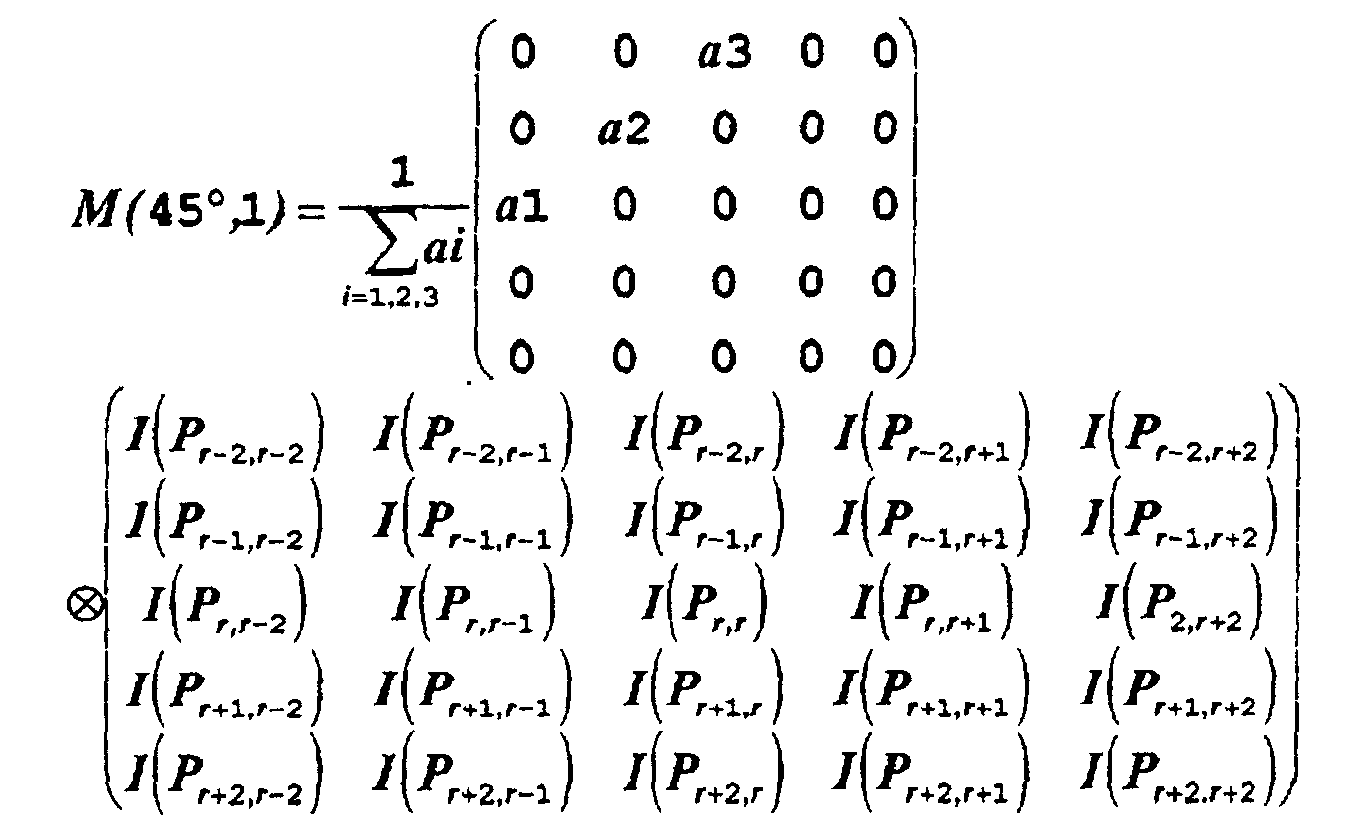
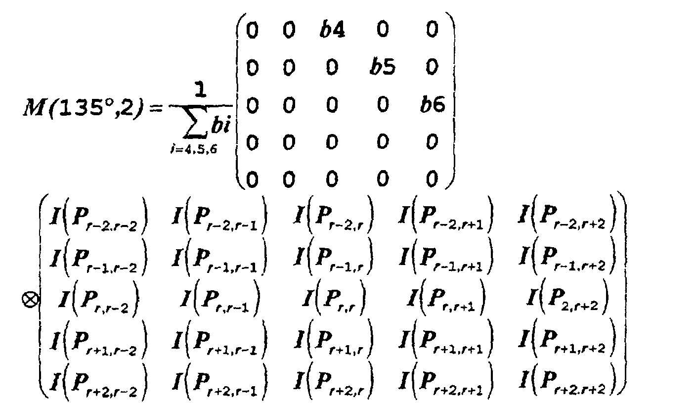
- dir
- filtered
- intensity
- pixels
- Prior art date
- Legal status (The legal status is an assumption and is not a legal conclusion. Google has not performed a legal analysis and makes no representation as to the accuracy of the status listed.)
- Expired - Lifetime
Links
Images


Classifications
-
- G—PHYSICS
- G06—COMPUTING OR CALCULATING; COUNTING
- G06T—IMAGE DATA PROCESSING OR GENERATION, IN GENERAL
- G06T5/00—Image enhancement or restoration
- G06T5/20—Image enhancement or restoration using local operators
Definitions
- the invention relates to a filtering process for focusing images, particularly digital images, or similar, which are composed of a plurality of single dot areas, named pixels having different individually variable luminous intensities, so as to generate all together an image, and which filtering process provides for each pixel of the image a correction of the intensity value of said pixel, which is calculated statistically, on the basis of combinations of high-pass filterings performed in at least one, preferably in at least four different directions with respect to the matrix of the pixels forming the image.
- each pixel under examination is subjected to high-pass filtering in multiple directions, using high-pass monodirectional filters. Then, the results of each monodirectional high-pass filtering are combined, after being weighted, to obtain statistical corrections of the filtered pixel.
- US patent US 5,390,264 discloses an image processing device for focussing digital images by generating an enhancement coefficient using a first difference, which is the difference of the target pixel signal minus the signal of the reference pixel positioned on a first direction; and the second difference, which is the target pixel signal minus the average of the signals of the second and third reference pixels, which are the reference pixels in the directions perpendicular to the first direction and on opposite sides of the target pixel.
- the target pixel signal is corrected by repeating this process for each of the reference pixels positioned on the four directions surrounding the target pixel.
- the invention is based on the problem of providing a filtering process for images made, particularly, of matrices of dot areas, being independent of each other, which allows to obtain sharp and focused images, with the highest fidelity with respect to the object under examination, and with a small computing time requirement.
- the invention solves the above problem with a process of the type described hereinbefore, in which the filter generates the correction value of each pixel of an image made of a set of pixels, that is of a pixel matrix, said correction value being based on the mean of the intensities of at least pairs of pixels, neighboring, i.e. being at predetermined distances from and on opposite sides of the pixel under examination, creating a corresponding new filtered image, composed of the corrected pixels.
- the correction value is calculated as an appropriately weighted mean between correction values obtained from the means of the intensities of at least one pair, or at least several pairs of pixels, of the pixel matrix under examination, on opposite sides of the pixel under examination, with reference to at least two different directions of the pixel matrix, preferably four directions of the pixel matrix, while said procedure is repeated for each pixel of the pixel matrix under examination, that is to be filtered.
- the correction value of each pixel is calculated on the weighted combination of the so-called directional correction values resulting from the means of at least two pairs of pixels on the opposite sides of the pixel under examination, the pixel pairs being oriented in a horizontal direction, in a vertical direction, and in two intermediate diagonal directions respectively, that is corresponding to the angular positions at 0°, 45°, 90°, 135°.
- the pixel intensity is weighted according to their distance from the pixel under examination, each intensity value being multiplied by a factor decreasing as the distance increases.
- the process according to the invention has the following steps:
- the directional correction values whose normalized sum gives the intensity correction value of the pixel under examination may be weighted in different ways, and particularly satisfactory results are obtained by weighting each directional correction value, by multiplying it by its own value.
- the filtering process according to the above description allows to remove the outline blurring effect in a digital image, through relatively fast calculations and thus a shorter computing time, especially in computers with a poorer and cheaper configuration. All this without causing any shift or deformation of lines as compared to the real situation, and thus ensuring a very high fidelity between the real situation and the displayed image, particularly when the image is the resultant of acquisition methods by echography or nuclear magnetic resonance.
- the filter performs nearly on-off corrections, therefore the corrected image may have lines or outlines between bright and dark areas with a saw-profile.
- the sign and the directional correction value, as well as the weight which may be assigned to the latter, may be thus calculated depending on the interval in which the intensity value of the pixel falls.
- the method according to the invention provides that an attenuation and/or enhancement factor be assigned to the directional correction value of intensity which is a function of the interval between the thresholds in which the intensity of the pixel under examination falls.
- the function on which the directional correction attenuating/enhancing factor depends is such, that said factor increases as the absolute value of the difference between the intensity of the pixel under examination and the central threshold increases.
- an attenuation factor of 1 is used when the intensity of the pixel under examination falls within the intervals at the maximum distance from the central threshold.
- the attenuation factor will increase of 2/(n+1) for each interval progressively departing from the central threshold.
- the signs and the absolute values of the individual directional correction values are obtained in the same way as in the case of a single threshold, assigning a negative or a positive sign, according to whether the intensity of the pixel under examination is lower or higher than the central threshold, and assigning, as an absolute value of the correction, the weighted difference between the mean values of intensity of the pixels on the opposite sides of the pixel under examination in the corresponding direction.
- the correction value is obtained by summing up the directional correction values, multiplied by their respective attenuation factor and by the corresponding weight of the single directional correction values, and through the division of such a sum by the sum of the weights of the directional correction values.
- the intensity correction values for the individual pixels under examination are attenuated or enhanced according to the absolute value of the difference between the intensity value of the filtered image, and the central directional threshold, which is defined as a grand mean of all means named M (dir, 1), and M (dir, 2) of the intensity values of the neighboring pixels on the opposite sides of the pixel under examination and in the corresponding direction.
- the filter according to the invention is advantageously applied to an image made of a pixel matrix, which has been previously submitted to low-pass filtering in order to remove noise, that is intensity fluctuations of pixels caused by noise while the image is being detected.
- the filter is simple and requires small processing times and a computing powers with respect to prior art filtering methods for sharpness enhancement. Moreover, this improvement also does not cause deformations of the image with respect to the real situation, therefore allowing for a high reproduction fidelity.
- the invention also relates to further improvements which form the subject of the dependent claims.
- Figs. 1 and 2 show a digital image in the form of a pixel matrix, as it should appear in case of full acquisition and reproduction fidelity, that is without noise and statistical variations.
- the image is composed of 9X6 pixels, represented with squares disposed on a grid made of six lines and nine columns.
- the diagram of fig. 2 shows the curve of intensity related to the third line from above.
- each pixel P i,j is indicated with a pair of numbers, i indicating the horizontal line, and j the column.
- Figure 3 shows a model of a possible digital image, which might be obtained by an acquisition system, such as a device for nuclear magnetic resonance image detection, or a system for echographic image detection.
- the image shown in fig. 3 contains, in the passage between bright and dark, pixels which are too dark or too bright.
- the image shown in fig. 3 might be either the image received directly by a detection system, or an image resulting from one or more previous processing operations, like, for example, a first filtering with a low-pass filter of any currently known or used type.
- the invention provides a method consisting of the following steps.
- an area of the image comprising odd numbers of lines and columns is considered, which has, at its center, i.e. at the crossing-point between the central line and the central column, the pixel under examination.
- the pixels of the examination area are arranged in a matrix, in which, the intensity values of the pixels are stored in their respective positions.
- the pixel under the examination is P 3,4 .
- the matrix corresponding to the pixels surrounding the pixel to be filtered is thus multiplied by a filtering matrix for each of the four different directions, corresponding to axes at 0°, 45°, 90°, and 135°.
- a matrix I k,l may be considered, which is centered on the intensity value I r,r of the central pixel P r,r to be filtered, and which has only three lines and three columns, whereas the filtering matrices for the 45° and 135° directions, that is the two diagonal directions, have, in the illustrated example, five lines and five columns.
- the intensity values I k,l of the pixels P k,l , surrounding the pixel under examination P r,r may be multiplied by a factor which is a function of their distance from the pixel under examination P r,r .
- the filtering matrices for the individual 0°, 45°, 90°, 135° directions i.e. for the horizontal and vertical directions and for the two diagonal directions have the following form: for the 0° direction, that is for the horizontal direction indicated with O in the figures. for the 90° direction, that is for the vertical direction, indicated with V in the figures. for the 45° direction, that is for one of the two diagonal directions, indicated with D1. and for the 135° direction, that is for one of the two diagonal directions, indicated with D2.
- ⁇ is defined as the sum of the products of the corresponding elements of the two matrices, i.e. those having the same positions, that is:
- This multiplication of the above matrices by the corresponding matrix 3X3 or 5X5 related to the intensities I k,l of the pixels P k,l , the definition of the modulus of the multiplication result and the division of the sum of fi, gi, ai, bi with i 1, 2, 3, by said modulus, generate a value for each direction, which is the modulus of the difference between the mean of the intensities M (dir, 1) and M (dir, 2) of the pixels P k,l , situated on one side of the pixel P r,r being filtered and that of the pixels P k,l , situated on the other side of the pixel P r,r being filtered, with reference to the corresponding 0°, 45°, 90° or 135° direction.
- the modulus of the difference between the means of the intensities M (dir, 1) and M (dir, 2) of the pixels k,l on the opposite sides of the pixel being filtered P r,r is used to calculate the intensity correction for the pixel being filtered P r,r in the corresponding direction and which, in the present disclosure and in the claims is defined as a directional correction C (dir), that is to say, with reference to the illustrated examples, according to the 0°, 45°, 90°, 135° directions.
- the final correction of the pixel being filtered is obtained through a weighted and normalized addition of the individual directional corrections.
- the directional correction is given by the modulus of the difference between the means M (dir, 1) and M (dir, 2) of the pixels P k,l on the opposite sides of the pixel being filtered P r,r in the corresponding direction.
- the weighting operation is performed by multiplying each directional correction C (dir) by a factor Q (dir), which is different for each of the directional corrections provided and, particularly, may be the value C (dir) itself for each direction.
- the process according to the invention provides threshold values, calculated for every filtering direction, the intensity value I r,r of the pixel being filtered P r,r being compared thereto.
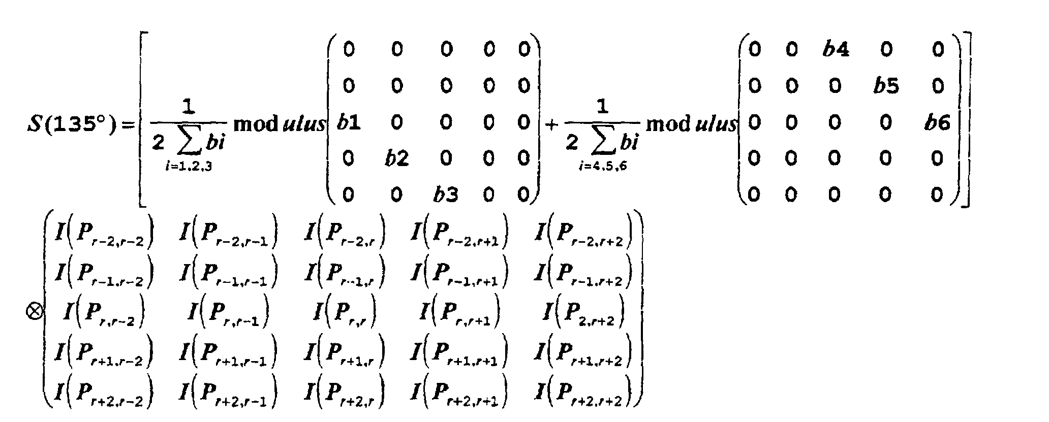
- This mean is used to define a threshold value S(0°), S(45°), S(90°), S(135°), for each 0°, 45°, 90°, 135° direction.
- the above thresholds which will be named, hereafter and in the claims, directional thresholds, are compared to the intensity I r,r of the central pixel P r,r , being filtered. This comparison determines the sign of the filtering correction to be applied to the intensity I r,r of the pixel P r,r being filtered, so that the correction is positive when I r,r is higher than the value of its respective directional threshold, whereas the correction is negative when I r,r is lower than the value of said directional value, this operation being executed for every directional threshold.
- the global correction value is obtained through the following formula: in which sign(x) is the function which takes the value (-1) when x ⁇ 0 and (+1) when x>0.
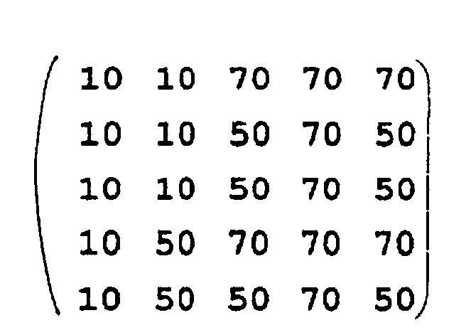
- the pixel P r,r has the value of 50, and the directional thresholds are indicated with S(0°), S(45°), S(90°), S(135°).
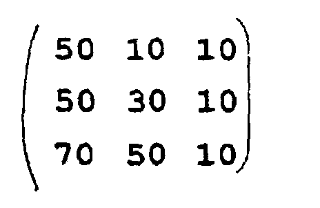
- the pixel matrices P k,1 have the following values: in the 0° and 90° directions and for the 45° and 135° directions
- Figures 10 to 14 show the area to be examined for filtering another pixel P x,x .
- the process is the same as described above as regards figures 5 to 9.
- the filtering process is repeated for every pixel P i,j of the image and provides a matrix for the correction of original intensities, which is as large as the original image, or as one portion thereof.
- the corrections of each pixel C(P r,r ), obtained through filtering may be multiplied by a further attenuation and/or, in case, enhancement weight.
- the weight may be obtained empirically, through a direct evaluation of the effect on the displayed image.
- the weight may be different for each correction C(P r,r ) or identical for all corrections of the individual pixels and is generally used to attenuate the correction, and is defined to be the same for all pixels being filtered.
- the reference for the filtering algorithm is still the original digital image, and the corrected intensity values are only used to produce the new filtered image, and are not involved during filtering.
- different matrices for directional filtering may be used, for example for diagonal directions.
- a single 3x3 matrix may be used for all steps of directional filtering, and it is not necessary to isolate two different fields of the digital image, centered on the pixel being filtered P r,r or P x,x .
- the process according to these two embodiments is very abrupt, as it suddenly increases or reduces the intensity of the pixel P r,r or P x,x being filtered.
- This discretized operation, of the on-off type may generate saw-profiled lines, that is with a slight zigzag profile.
- the invention provides the improvement of setting a statistical weighting factor of the individual directional corrections C (dir), accounting for the distance between the original value of the pixel being filtered, and the corresponding directional threshold S(dir).
- the weighting factor may be any function of the modulus of the difference between the value of the directional threshold and the intensity of the pixel being filtered.
- the dependence of the weighting factor on the modulus of the difference between the directional threshold value and the intensity of the pixel being filtered is a discrete function which assigns each quantity range or interval of said difference a fixed value, there being provided a weighting factor 1, for very high difference values, whereas, for smaller difference values, the weighting factor is a predetermined fraction.
- the intervals used to calculate the additional weighting factor for a directional correction are obtained by defining several thresholds, i.e. at least three directional thresholds.
- the thresholds are always calculated starting from the mean of the mean values of the neighboring pixels on the two opposite sides of the pixel P r,r being filtered, and with reference to the direction under examination.
- the thresholds 1, 2, 3 divide the difference between the means of the pixels P k,l on the two opposing sides of the pixel being filtered P r,r , and in the corresponding direction, into four intervals.
- the weighting factor of the directional correction C(dir) for the pixel P r,r being filtered is 1.
- the weighting factor of the corresponding directional correction C(dir) is a fraction of 1, for example 0.5.
- Fig. 15 shows the intensity diagram of the three pixels P r,r-1 , P r,r and P r,r+1 , which are aligned with the pixel being filtered P r,r in the horizontal direction of the image, that is of an area of the image, made of nine pixels, whose center is a pixel being filtered P r,r with different values of I(P r,r ).
- the remaining pixels P k,l are like in the previous example of figures 5 to 9, that is: in the 0° and 90° directions and for the 45° and 135° directions.
- This expedient allows for a reduction of the correction values for the pixel being filtered, depending on the higher or lower closeness of the intensity value to the central threshold obtained as a grand mean of the intensity values of the pixels on the opposite sides of the pixel being filtered P r,r for each direction.
- This also reflects a certain statistical concept which reasonably accounts for the fact that, the closer the intensity of the pixel P r,r being filtered is to the central directional threshold value, the more the certainty that its intensity will be decreased or increased is reduced.
- thresholds involve an attenuation of the on-off effect and an outline-straightening effect, the so-called smoothing, without causing said outlines to be deformed or shifted as compared to the original situation and thus maintaining a high reproduction fidelity and a considerable image sharpness.
- the algorithm which describes the high-pass filtering process according to the invention is very simple and does not need a very high computing power. This involves a remarkable filtering speed and the use of cheap computers.
- the invention is not limited to what has been described and illustrated herein, but may be greatly varied. So, the directions and the structure of matrices, as well as the areas of the image or of the pixel matrix to be considered for filtering the pixel P r,r may be chosen beneath the limits of the description and illustrations included herein. For example, a grater number of pixels for each direction may be considered.
- the directions though the use of vertical, horizontal, and diagonal directions is much simpler, may be also intended in a broader sense, that is as ideal paths joining a certain number of pixels at predetermined distances and in predetermined positions with respect to each other and to the pixel being filtered, and whose eventually weighted means are mutually statistically processed and used, as a mean to obtain comparison thresholds, and as a difference to define absolute correction values.
- the directions may also be polygonal lines ideally connecting any different pixel of the area under examination.
- the weighting functions of the intensity values of the pixels P k,l which are selected for filtering the pixel P r,r and may be varied according to their distance from the pixel being filtered, as well as the weighting factors of the directional corrections C(dir), the number of directional thresholds and the statistical attenuation weights related to the different intervals defined by said thresholds are also freely variable. The whole without departing from the guiding principle disclosed above and claimed below.
Landscapes
- Physics & Mathematics (AREA)
- General Physics & Mathematics (AREA)
- Engineering & Computer Science (AREA)
- Theoretical Computer Science (AREA)
- Image Processing (AREA)
- Blocking Light For Cameras (AREA)
- Instruments For Viewing The Inside Of Hollow Bodies (AREA)
- Automatic Focus Adjustment (AREA)
Description

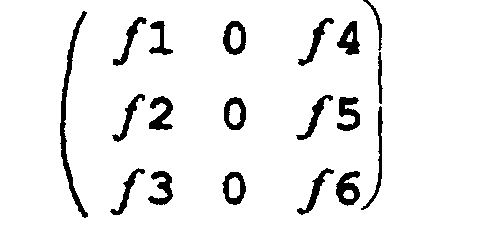


fl=f3=-f4=-f6=g1=g3=-g4=-g6=al=a3=-a4=-a6=bl=b3=-b4= -b6= 1
and f2=-f5=g2=-g5=a2=-a5=b2=-b5= 2, thus obtaining the following directional filtering matrices.






and
f2=-f5=g2=-g5=a2=-a5=b2=-b5= 2

S(0°)=55>I(Pr,r)=50;
directional correction sign: (-1)
weighted directional correction: |20| × |20| = 40
S(90°)=45<I(Pr,r)=50;
directional correction sign: (+1)
weighted directional correction: |50| × |50| = 2500
S(45°)=52,5>I(Pr,r)=50;
directional correction sign: (-1)
weighted directional correction: |25| × |25| = 625
S (135°) =42,5<I (Pr,r) =50;
directional correction sign: (+1) weighted directional correction: |35| × |35| = 1225

S(0°)=32,5>I(Px,x)=30;
directional correction sign: (-1)
weighted directional correction: l25l × l25l = 625
S(90°)=32,5>I(Px,x)=30;
directional correction sign: (-1)
weighted directional correction: |45|×|45|=2025
S(45°)=32,5>I(Px,x)=30;
directional correction sign: (-1)
weighted directional correction: |45|×|45|=2025
S(135°)=27,5<I(Px,x)=30;
directional correction sign: (+1) weighted directional correction: |35|×|35|=1225







Claims (18)
- Filtering process for focusing images, particularly digital images, which are composed of a plurality of pixels (Pi,j) having different individually variable luminous intensitiesso as to generate all together an image, and which filtering process provides for each pixel (Pi,j) of the image an intensity correction value (C(Pi,j)) for enhancing or attenuating the intensity value of said pixel

(Pi,j), the said intensity correction value being calculated statistically from a combination of the intensities of reference pixels positioned in the surrounding of the pixel to be filtered according to at least one, preferably at least four different directions (0°, 45°, 90°, 135°) with respect to the matrix of the pixels (Pi,j) forming the image by determining
the correction value (C(Pr,r)) of the intensity of each pixel (Pr,r; Px,x) from the mean of the intensities of at least one pair, preferably at least several pairs of pixels being next to, that is at predetermined distances from and on opposite sides of the pixel to be filtered (Pr,r; Px,x), with reference to each of the predefined directions (0°, 45°, 90°, 135°), said procedure being repeated for each pixel (Pi,j) of the pixel matrix under examination, that is to be filtered, creating a corresponding new filtered image, composed of the corrected pixels
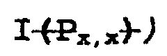
characterised, by the following steps:a) Calculating, for each of at least one, preferably four different directions, which may be defined with reference to the pixel matrix (Pi,j), the means of the intensity values (Ii,j), appropriately weighted (fi, gi, ai, bi), if necessary, with respect to distance, of two or more pixels of the pixel matrix (Pi,j), that is of the image to be filtered, said pixels being on opposite sides of the pixel under examination (Pr,r; Px,x) and aligned along a predetermined direction (0°, 45°, 90°, 135°);b) Calculating, for each of at least one, preferably of the four directions (0°, 45°, 90°, 135°), which may be defined with reference to the pixel matrix (Pi,j) under examination, a so-called directional intensity threshold (S(dir); S(0°), S(45°), S(90°), S(135°)), which for each direction equals the mean or the means of the intensities of the pixels on the opposite sides of the pixel being filtered relating to the corresponding direction;c) Calculating, for each of at least one, preferably of the four directions (0°, 45°, 90°, 135°), which may be defined with reference to the pixel matrix (Pi,j), a so-called directional, i.e. direction-dependent correction value (C(dir)), which is the absolute value of the difference between the means of the intensities of the neighboring pixels which are positioned on the two opposite sides of the pixel under examination with reference to the predetermined direction, and which are aligned in the said direction, the said directional correction value (C(dir)) being appropriately weighted by multiplying it by a weighting factor (Q(dir)), the said directional correction value (C(dir)) being assigned a positive or negative sign, according to whether the intensity of the pixel being filteredis higher or lower than the threshold value (S(dir); S(0°), S(45°), S(90°), S(135°)) for the corresponding direction. d) Calculating the intensity correction value of the pixel being filtered, by adding up the individual appropriately weighted directional corrections values (C(dir)), as in the previous step c) and by normalizing said sum by dividing it by the sum of the weighting multiplying factors (Q(dir)) of the directional correction values (C(dir));e) Adding the correction value (C(Pr,r), C(Px,x)) obtained therefrom to the intensity value
 of the pixel being filtered;
 g) Creating a digital image, in the form of a pixel matrix, in which, in the corresponding position of the pixel being filtered (Pr,r; Px,x), the corrected intensity of the filtered pixel (Pr,r; Px,x) is displayed;f) Repeating the previous steps a) to e) for each of at least one predetermined part or of all the pixels (Pi,j) of the pixel matrix.
 - Process as claimed in claim 1, characterized in that the directional weighting factor (Q(dir)) of the directional correction values (C(dir)), is equal to the modulus of the associated directional correction value (C(dir)).
- Process as claimed in claims 2 or 3, characterized in that for each direction of the at least one, preferably of the four directions (0°, 45°, 90°, 135°), which may be defined with reference to the pixel matrix (Pi,j), number n of directional thresholds ( S(dir, k); S(1), S(2), S(3), S(n)) is defined, by dividing for each direction the difference between the means of the pixels on the two opposing sides of the pixel being filtered by the number of thresholds (n) thus generating a number of intervals (n+1), in which the intensity of the pixel being filtered (Pr,r, Px,x) may fall, and that a weighting factor is assigned to the directional correction value (C(dir)) of intensity for the corresponding direction, which is a function of the interval between the directional thresholds ( S(dir k); S(1), S(2), S(3), S(n)) in which the intensity of the pixel being filtered falls.
- Process as claimed in claim 3, characterized in that the weighting factor (W) is such, that the factor (W) increases as the absolute value of the difference between the intensity (Ir,r) of the pixel being filtered (Pr,r) and a central threshold (S(2)) of the n thresholds increases.
- Process as claimed in claim 4, characterized in that the maximum weighting factor (W) is 1.
- Process as claimed in claims 4 or 5, characterized in that the function defining the dependence of the weighting factor (W) on the intervals defined by the directional thresholds (S(dir, k); S(1), S(2), S(3),..., S(n)), is a discrete function having fixed decreases of 2/(n+1) for each interval defined by n thresholds, starting from the value of 1, corresponding to the interval outside the highest or lowest threshold, with respect to central threshold, said function defining the weighting factors (W) being symmetrical with respect to the said central threshold (S[(n+1)/2], S(2)), in case of an odd number of thresholds.
- Process as claimed in one or more of the preceding claims, characterized in that, for each pixel being filtered (Pr,r, Px,x), a surrounding pixel area (Pk,l) is considered, the pixel being filtered (Pr,r, Px,x) occupying the center thereof, and a matrix of the intensity values (I(Pk,l)) of pixels (Pk,l), with a predetermined number of lines (z) and a predetermined number of columns (w) is generated, the correction values being obtained through filtering matrices for at least one, preferably more than one, especially four directions, said matrices having the same dimensions (z,w) as the matrices corresponding to the areas under examination÷ and having elements other than zero corresponding to the pixels (Pk,l) whose intensity value is used to calculate the corresponding directional correction value (C(dir)).
- Process as claimed in claim 7, characterized in that four directions are considered, oriented 0°, 45°, 90°, 135°, with respect to the lines of the matrix under examination (Pk,l), which is centered around the pixel being filtered (Pr,r; Px,x), the filtering matrices being of the following type:for the 0° direction, that is for the horizontal direction (O).
 for the 90° direction, that is for the vertical direction (V).
 for the 45° direction (D1). and
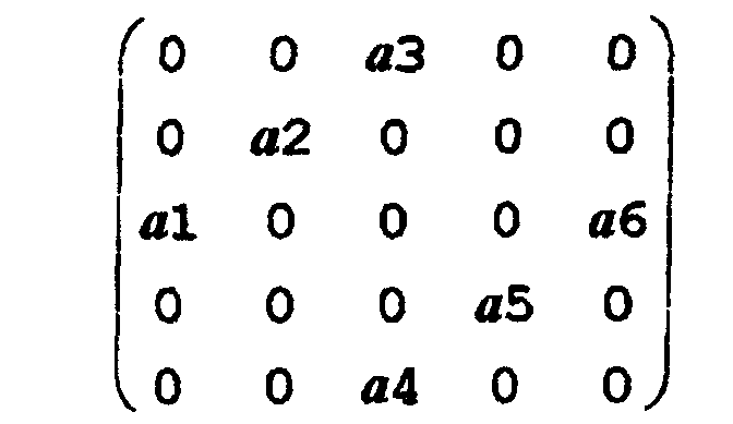 for the 135° direction (D2).
in which the factors fi, gi, ai, bi, with i = 1, 2, ..., 6, are weighting factors for the intensity values of the pixels surrounding the pixel under examination, that is the central pixel (Pr,r) to be filtered, said factors being functions of the distance of the corresponding pixel from the pixel being filtered (Pr,r). - Process as claimed in claim 8, characterized in that the directional thresholds are calculated as follows:in which the modulus function is defined as the matrix of the moduli, i.e. of the absolute values of the matrix elements, and in which ⊗ defines a particular operator defined as convolution of these matrices,
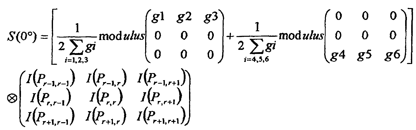 and that the same is applicable for the other directions:


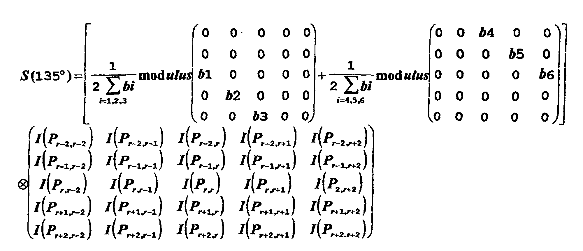
- Process as claimed in claim 9, characterized in that, in the diagonal 45° and 135° directions, the filtering matrices may also have the same dimensions as those in the 0° and 90° directions, that is:
of the type: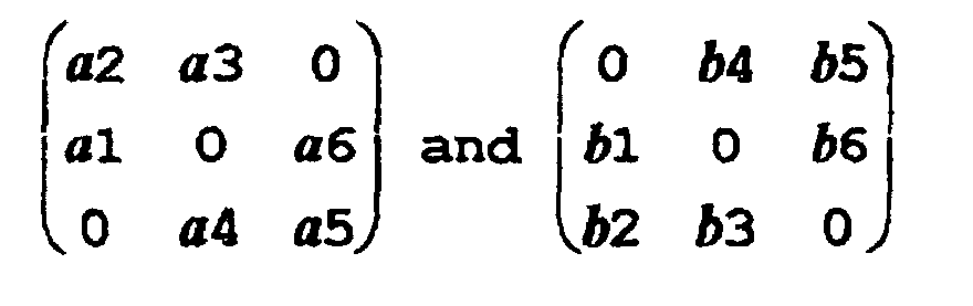
- Process as claimed in one or more of the preceding claims 7 to 10, characterized in that f1=f3=-f4=-f6 and f2=-f5; and accordingly g1=g3=-g4=-g6 and g2=-g5; a1=a3=-a4=-a6 and a2=-a5; and b1=b3=-b4=-b6 and b2=-b5.
- Process as claimed in claim 11, characterized in that f1=g1=a1=b1 and f2=g2=a2=b2.
- Process as claimed in claim 12, characterized in that f1=f3=-f4=-f6=g1=g3=-g4=-g6=a1=a3=-a4=-a6=b1=b3=-b4=-b6=1 and f2=-f5=g2=-g5=a2=-a5=b2=-b5=2.
- Process as claimed in one or more of the preceding claims, characterized in that the correction value (C(Pr,r)) of the pixel being filtered (Pr,r; Px,x) is obtained through the following formula:in which sign(x) is the function which takes the value (-1) when x<0 and (+1) when x>0

and in which the variable dir defines four directions in the pixel matrix;
C(dir) is the correction value dependent on the direction and is defined as the modulus of the difference between the mean of the intensities (M(dir, 1)) of the pixels situated on one side of the pixel (Pr,r; Px,x) being filtered and that (M(dir, 2)) of the pixels situated on the other side of the pixel (Pr,r; Px,x) being filtered with reference to the different directions; Q(dir) is a weighting factor of the different correction dependent values; S(dir) is a direction dependent threshold; - Process as claimed in one or more of the preceding claims, characterized in that, for each direction, several directional thresholds are determined as follows:calculating the intensity means (M(dir,1) ; M(dir,2)) of the pixels (Pk,1) on each of the opposite sides of the pixel (Pr,r) being filtered, with reference to the directions, dir=0°, 45°, 90°, 135° as
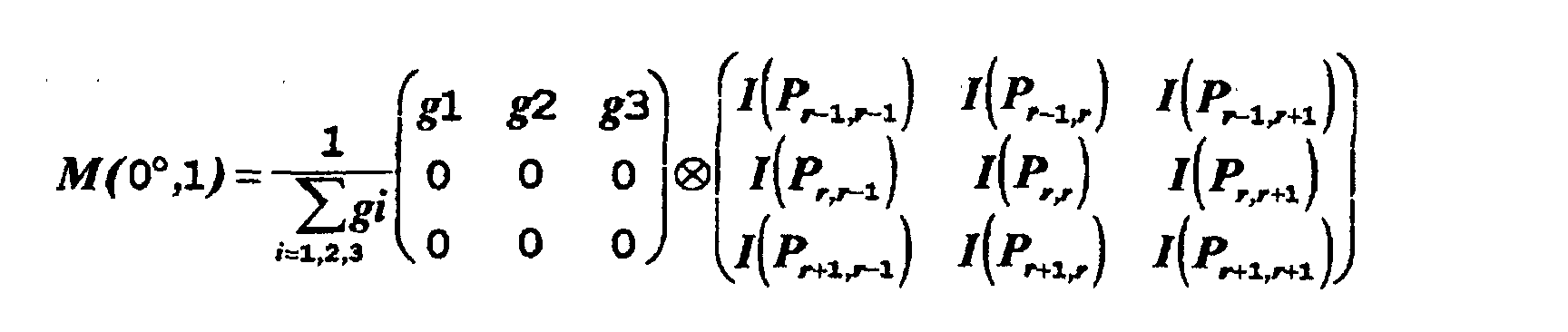 in which the symbol ⊗ indicates the convolution of matrices: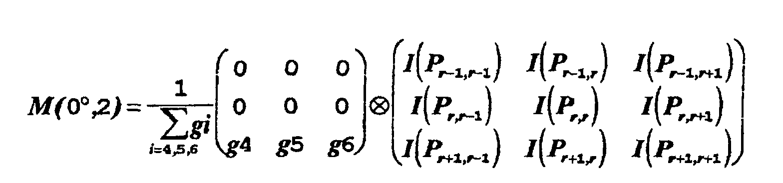


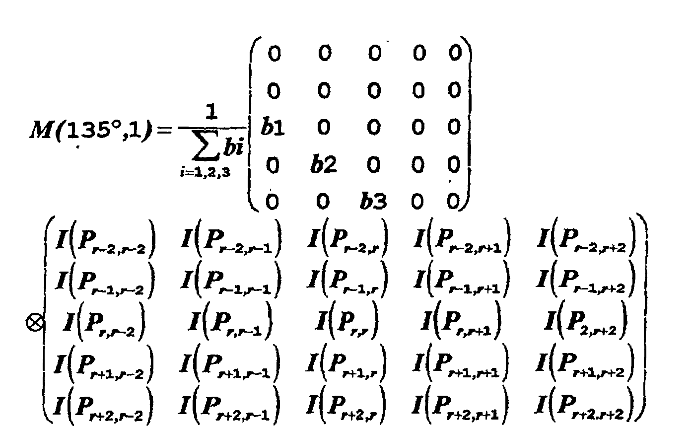
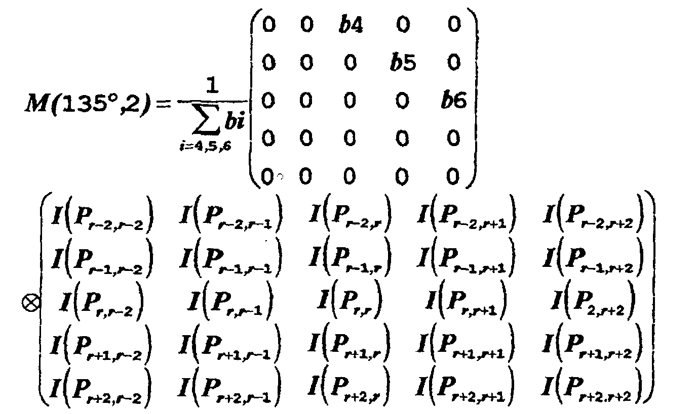 calculating a number of k different threshold values s(dir, k) with k= 1,...,n according to:
S(dir,k)= [(n+1-k)xM(dir,1)+k x M(dir,2)]/(n+1) with dir= 0°, 45°, 90°, 135°. - Process as claimed in claim 15, characterized in that, three thresholds (S(1), S(2), S(3)) are given one of which is a central threshold having a value centered between the values of the other two thresholds and that a weighting factors (W(s)) for the directional corrections values (C(dir)) is defined which has the value of 0.5 in the intervals between the central threshold (S(2)) and the two lower and higher thresholds (S(1), S(3)), and of 1 in the intervals above the highest threshold (S(3)) and below the lowest threshold (S(1)).
- Process as claimed in one or more of the preceding claims, characterized in that the intensity correction value of the pixel being filtered, is weighted by an attenuation/enhancement factor, before being added to the original intensity of the pixel being filtered, this attenuation/enhancement factor for the intensity correction value of the pixel being filtered, being empirically defined by evaluating the visual effect on the displayed image.
- Process as claimed in claim 17, characterized in that the attenuation/enhancement factor for the intensity correction of the pixel being filtered, may be different for different pixels or groups thereof, or the same throughout the pixel matrix.
Applications Claiming Priority (2)
| Application Number | Priority Date | Filing Date | Title |
|---|---|---|---|
| ITSV970011 | 1997-02-21 | ||
| IT97SV000011A IT1294043B1 (en) | 1997-02-21 | 1997-02-21 | HIGH-PASS FILTERING PROCEDURE FOR FOCUSING IMAGES, IN PARTICULAR DIGITAL IMAGES. |
Publications (2)
| Publication Number | Publication Date |
|---|---|
| EP0860794A1 EP0860794A1 (en) | 1998-08-26 |
| EP0860794B1 true EP0860794B1 (en) | 2003-05-02 |
Family
ID=11408208
Family Applications (1)
| Application Number | Title | Priority Date | Filing Date |
|---|---|---|---|
| EP98102869A Expired - Lifetime EP0860794B1 (en) | 1997-02-21 | 1998-02-19 | Filtering process for focussing images |
Country Status (5)
| Country | Link |
|---|---|
| US (1) | US6141461A (en) |
| EP (1) | EP0860794B1 (en) |
| DE (1) | DE69813931T2 (en) |
| ES (1) | ES2197391T3 (en) |
| IT (1) | IT1294043B1 (en) |
Families Citing this family (17)
| Publication number | Priority date | Publication date | Assignee | Title |
|---|---|---|---|---|
| AU766343B2 (en) * | 1998-10-09 | 2003-10-16 | Motorola Australia Pty Ltd | A method and apparatus for detecting focus of a digital image |
| US6320987B1 (en) * | 1998-10-16 | 2001-11-20 | Neo Paradigm Labs, Inc. | Pre-DCT residue filter |
| US6738502B1 (en) * | 1999-06-04 | 2004-05-18 | Kairos Scientific, Inc. | Multispectral taxonomic identification |
| US7333672B2 (en) * | 2000-03-30 | 2008-02-19 | British Telecommunications Public Limited Company | Image processing system/network which performs recognition process only upon regions having higher high spatial frequency content |
| EP1246473A1 (en) * | 2001-03-27 | 2002-10-02 | Koninklijke Philips Electronics N.V. | Image pickup apparatus equipped with contour compensation circuit and method carried out in such an apparatus |
| US7822285B2 (en) * | 2004-05-20 | 2010-10-26 | Omnivision Technologies, Inc. | Methods and systems for locally adaptive image processing filters |
| JP2006119723A (en) * | 2004-10-19 | 2006-05-11 | Canon Inc | Image processing apparatus and image processing method |
| DE102004061507B4 (en) * | 2004-12-21 | 2007-04-12 | Siemens Ag | Method for correcting inhomogeneities in an image and imaging device therefor |
| JP4621944B2 (en) * | 2005-01-19 | 2011-02-02 | 株式会社メガチップス | Image filter device, method and computer program |
| KR100696162B1 (en) * | 2006-08-11 | 2007-03-20 | 엠텍비젼 주식회사 | Noise reduction device and noise reduction method of an image, and a recording medium having recorded thereon a program |
| US20080284854A1 (en) * | 2007-05-18 | 2008-11-20 | Dts, Inc. | System and method of static pattern removal from movies captured using a digital CCD camera |
| TWI387319B (en) * | 2009-06-02 | 2013-02-21 | Novatek Microelectronics Corp | Circuit and method for image processing |
| US9995766B2 (en) * | 2009-06-16 | 2018-06-12 | The Regents Of The University Of California | Methods and systems for measuring a property of a macromolecule |
| US9870375B2 (en) * | 2013-12-20 | 2018-01-16 | Nvidia Corporation | Image analysis of display content for dynamic adjustment of a continuous scan display |
| US9830871B2 (en) | 2014-01-03 | 2017-11-28 | Nvidia Corporation | DC balancing techniques for a variable refresh rate display |
| US9711099B2 (en) | 2014-02-26 | 2017-07-18 | Nvidia Corporation | Techniques for avoiding and remedying DC bias buildup on a flat panel variable refresh rate display |
| US9940898B2 (en) | 2016-02-25 | 2018-04-10 | Nvidia Corporation | Variable refresh rate video capture and playback |
Family Cites Families (3)
| Publication number | Priority date | Publication date | Assignee | Title |
|---|---|---|---|---|
| US4731865A (en) * | 1986-03-27 | 1988-03-15 | General Electric Company | Digital image correction |
| US5070465A (en) * | 1987-02-25 | 1991-12-03 | Sony Corporation | Video image transforming method and apparatus |
| JP3092024B2 (en) * | 1991-12-09 | 2000-09-25 | 松下電器産業株式会社 | Image processing method |
-
1997
- 1997-02-21 IT IT97SV000011A patent/IT1294043B1/en active IP Right Grant
-
1998
- 1998-02-19 EP EP98102869A patent/EP0860794B1/en not_active Expired - Lifetime
- 1998-02-19 DE DE69813931T patent/DE69813931T2/en not_active Expired - Lifetime
- 1998-02-19 ES ES98102869T patent/ES2197391T3/en not_active Expired - Lifetime
- 1998-02-20 US US09/027,218 patent/US6141461A/en not_active Expired - Lifetime
Also Published As
| Publication number | Publication date |
|---|---|
| ES2197391T3 (en) | 2004-01-01 |
| ITSV970011A1 (en) | 1998-08-21 |
| US6141461A (en) | 2000-10-31 |
| DE69813931T2 (en) | 2004-02-26 |
| EP0860794A1 (en) | 1998-08-26 |
| IT1294043B1 (en) | 1999-03-15 |
| ITSV970011A0 (en) | 1997-02-21 |
| DE69813931D1 (en) | 2003-06-05 |
Similar Documents
| Publication | Publication Date | Title |
|---|---|---|
| EP0860794A1 (en) | High-pass filtering process for focussing images, particularly digital images | |
| EP2130175B1 (en) | Edge mapping incorporating panchromatic pixels | |
| US7016549B1 (en) | Image processing method for direction dependent low pass filtering | |
| EP0352016B1 (en) | Method and system for enhancement of a digitized image | |
| EP0555674B1 (en) | Image rendering system and associated method for minimizing contours in a quantized digital color image | |
| US6049635A (en) | Dotted image area detecting apparatus and dotted image area detecting method | |
| CN110866503B (en) | Abnormality detection method and abnormality detection system for finger vein equipment | |
| US4638369A (en) | Edge extraction technique | |
| US7092570B2 (en) | Removing color aliasing artifacts from color digital images | |
| DE10230112A1 (en) | Method and apparatus for enhancing images using edge alignment | |
| EP1439490A2 (en) | Shoot suppression in image Enhancement | |
| EP0239113B1 (en) | Method of smoothing image data | |
| CN113192094A (en) | Ghost outline extraction method, electronic device and storage medium | |
| EP0380720A1 (en) | Image processing method | |
| DE69029429T2 (en) | Binary image reduction process | |
| EP0504633A2 (en) | Minimum difference processor | |
| US7903901B2 (en) | Recursive filter system for a video signal | |
| EP0902585A2 (en) | Method and apparatus for image processing | |
| US6876778B2 (en) | Edge enhancement method and apparatus in digital image scalar-up circuit | |
| CN1366275A (en) | Technology for removing false image of storage of liquid crystal projector | |
| JP5933690B2 (en) | Image processing apparatus and method, and image processing program | |
| JP7414455B2 (en) | Focus detection device and method, and imaging device | |
| US8155470B2 (en) | Device for removing noise in image data | |
| He et al. | Bilateral edge detection on a virtual hexagonal structure | |
| US6278803B1 (en) | Interpolation apparatus for offset sampling signals |
Legal Events
| Date | Code | Title | Description |
|---|---|---|---|
| PUAI | Public reference made under article 153(3) epc to a published international application that has entered the european phase |
Free format text: ORIGINAL CODE: 0009012 |
|
| AK | Designated contracting states |
Kind code of ref document: A1 Designated state(s): DE ES FR GB IT |
|
| AX | Request for extension of the european patent |
Free format text: AL;LT;LV;MK;RO;SI |
|
| 17P | Request for examination filed |
Effective date: 19990212 |
|
| AKX | Designation fees paid |
Free format text: DE ES FR GB IT |
|
| RBV | Designated contracting states (corrected) |
Designated state(s): DE ES FR GB IT |
|
| 17Q | First examination report despatched |
Effective date: 20011019 |
|
| RTI1 | Title (correction) |
Free format text: FILTERING PROCESS FOR FOCUSSING IMAGES |
|
| GRAH | Despatch of communication of intention to grant a patent |
Free format text: ORIGINAL CODE: EPIDOS IGRA |
|
| RTI1 | Title (correction) |
Free format text: FILTERING PROCESS FOR FOCUSSING IMAGES |
|
| GRAH | Despatch of communication of intention to grant a patent |
Free format text: ORIGINAL CODE: EPIDOS IGRA |
|
| GRAA | (expected) grant |
Free format text: ORIGINAL CODE: 0009210 |
|
| AK | Designated contracting states |
Designated state(s): DE ES FR GB IT |
|
| REG | Reference to a national code |
Ref country code: GB Ref legal event code: FG4D |
|
| REF | Corresponds to: |
Ref document number: 69813931 Country of ref document: DE Date of ref document: 20030605 Kind code of ref document: P |
|
| REG | Reference to a national code |
Ref country code: ES Ref legal event code: FG2A Ref document number: 2197391 Country of ref document: ES Kind code of ref document: T3 |
|
| PLBE | No opposition filed within time limit |
Free format text: ORIGINAL CODE: 0009261 |
|
| STAA | Information on the status of an ep patent application or granted ep patent |
Free format text: STATUS: NO OPPOSITION FILED WITHIN TIME LIMIT |
|
| ET | Fr: translation filed | ||
| 26N | No opposition filed |
Effective date: 20040203 |
|
| PG25 | Lapsed in a contracting state [announced via postgrant information from national office to epo] |
Ref country code: IT Free format text: LAPSE BECAUSE OF NON-PAYMENT OF DUE FEES;WARNING: LAPSES OF ITALIAN PATENTS WITH EFFECTIVE DATE BEFORE 2007 MAY HAVE OCCURRED AT ANY TIME BEFORE 2007. THE CORRECT EFFECTIVE DATE MAY BE DIFFERENT FROM THE ONE RECORDED. Effective date: 20050219 |
|
| REG | Reference to a national code |
Ref country code: FR Ref legal event code: CA |
|
| PGRI | Patent reinstated in contracting state [announced from national office to epo] |
Ref country code: IT Effective date: 20091201 |
|
| PGFP | Annual fee paid to national office [announced via postgrant information from national office to epo] |
Ref country code: DE Payment date: 20110215 Year of fee payment: 14 Ref country code: FR Payment date: 20110222 Year of fee payment: 14 |
|
| PGFP | Annual fee paid to national office [announced via postgrant information from national office to epo] |
Ref country code: ES Payment date: 20110211 Year of fee payment: 14 Ref country code: GB Payment date: 20110217 Year of fee payment: 14 |
|
| REG | Reference to a national code |
Ref country code: DE Ref legal event code: R082 Ref document number: 69813931 Country of ref document: DE Representative=s name: DR. HOFFMEISTER & BISCHOF, PATENTANWALT UND RE, DE Ref country code: DE Ref legal event code: R082 Ref document number: 69813931 Country of ref document: DE Representative=s name: DR. HOFFMEISTER & BISCHOF, DE |
|
| GBPC | Gb: european patent ceased through non-payment of renewal fee |
Effective date: 20120219 |
|
| REG | Reference to a national code |
Ref country code: FR Ref legal event code: ST Effective date: 20121031 |
|
| REG | Reference to a national code |
Ref country code: DE Ref legal event code: R119 Ref document number: 69813931 Country of ref document: DE Effective date: 20120901 |
|
| PG25 | Lapsed in a contracting state [announced via postgrant information from national office to epo] |
Ref country code: FR Free format text: LAPSE BECAUSE OF NON-PAYMENT OF DUE FEES Effective date: 20120229 Ref country code: GB Free format text: LAPSE BECAUSE OF NON-PAYMENT OF DUE FEES Effective date: 20120219 |
|
| PG25 | Lapsed in a contracting state [announced via postgrant information from national office to epo] |
Ref country code: DE Free format text: LAPSE BECAUSE OF NON-PAYMENT OF DUE FEES Effective date: 20120901 |
|
| REG | Reference to a national code |
Ref country code: ES Ref legal event code: FD2A Effective date: 20130708 |
|
| PG25 | Lapsed in a contracting state [announced via postgrant information from national office to epo] |
Ref country code: ES Free format text: LAPSE BECAUSE OF NON-PAYMENT OF DUE FEES Effective date: 20120220 |
|
| PGFP | Annual fee paid to national office [announced via postgrant information from national office to epo] |
Ref country code: IT Payment date: 20170222 Year of fee payment: 20 |